Multilayer Switching Lab - Router Alley
Multilayer Switching Lab - Router Alley
Multilayer Switching Lab - Router Alley

You also want an ePaper? Increase the reach of your titles
YUMPU automatically turns print PDFs into web optimized ePapers that Google loves.
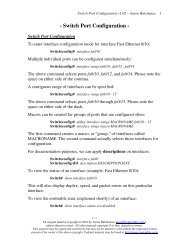
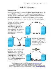
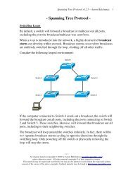
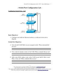
<strong>Multilayer</strong> <strong>Switching</strong> – <strong>Lab</strong><br />
Basic Objectives:<br />
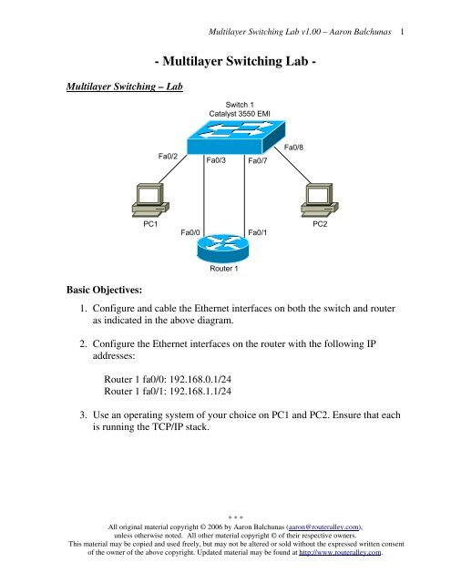
PC1<br />
<strong>Multilayer</strong> <strong>Switching</strong> <strong>Lab</strong> v1.00 – Aaron Balchunas<br />
- <strong>Multilayer</strong> <strong>Switching</strong> <strong>Lab</strong> -<br />
Fa0/2<br />
Switch 1<br />
Catalyst 3550 EMI<br />
Fa0/3<br />
Fa0/7<br />
Fa0/0 Fa0/1<br />
<strong>Router</strong> 1<br />
Fa0/8<br />
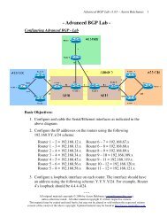
1. Configure and cable the Ethernet interfaces on both the switch and router<br />
as indicated in the above diagram.<br />
2. Configure the Ethernet interfaces on the router with the following IP<br />
addresses:<br />
<strong>Router</strong> 1 fa0/0: 192.168.0.1/24<br />
<strong>Router</strong> 1 fa0/1: 192.168.1.1/24<br />
3. Use an operating system of your choice on PC1 and PC2. Ensure that each<br />
is running the TCP/IP stack.<br />
* * *<br />
All original material copyright © 2006 by Aaron Balchunas (aaron@routeralley.com),<br />
unless otherwise noted. All other material copyright © of their respective owners.<br />
This material may be copied and used freely, but may not be altered or sold without the expressed written consent<br />
of the owner of the above copyright. Updated material may be found at http://www.routeralley.com.<br />
PC2<br />
1
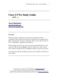
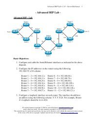
<strong>Multilayer</strong> <strong>Switching</strong> – <strong>Lab</strong> (continued)<br />
PC1<br />
Fa0/2<br />
<strong>Multilayer</strong> <strong>Switching</strong> <strong>Lab</strong> v1.00 – Aaron Balchunas<br />
Switch 1<br />
Catalyst 3550 EMI<br />
Fa0/3<br />
Fa0/7<br />
Fa0/0 Fa0/1<br />
<strong>Router</strong> 1<br />
Standard VLAN Routing Objectives:<br />
Fa0/8<br />
4. Create VLANs 100 and 200 on Switch 1. Assign switchports fa0/2 and<br />
fa0/3 to VLAN 100, and switchports fa0/7 and fa0/8 to VLAN 200.<br />
______________________________________________________________________<br />
______________________________________________________________________<br />
______________________________________________________________________<br />
5. Configure the router to pass traffic between VLANs 100 and 200.<br />
______________________________________________________________________<br />
______________________________________________________________________<br />
______________________________________________________________________<br />
6. Configure a default gateway on each PC, pointing to the appropriate<br />
interface on the router. Ensure connectivity between the two PC’s.<br />
______________________________________________________________________<br />
______________________________________________________________________<br />
______________________________________________________________________<br />
* * *<br />
All original material copyright © 2006 by Aaron Balchunas (aaron@routeralley.com),<br />
unless otherwise noted. All other material copyright © of their respective owners.<br />
This material may be copied and used freely, but may not be altered or sold without the expressed written consent<br />
of the owner of the above copyright. Updated material may be found at http://www.routeralley.com.<br />
PC2<br />
2
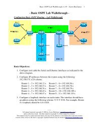
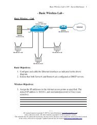
<strong>Multilayer</strong> <strong>Switching</strong> – <strong>Lab</strong> (continued)<br />
Fa0/2<br />
<strong>Router</strong>-on-a-Stick Objectives:<br />
<strong>Multilayer</strong> <strong>Switching</strong> <strong>Lab</strong> v1.00 – Aaron Balchunas<br />
Switch 1<br />
Catalyst 3550 EMI<br />
Fa0/5<br />
Fa0/8<br />
PC1 PC2<br />
Fa0/0<br />
<strong>Router</strong> 1<br />
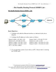
7. Reconfigure and cable the Ethernet interfaces on both the switch and router<br />
as indicated in the above new diagram. Ensure that VLANs 100 and 200<br />
are still created, and that switchport fa0/2 is assigned to VLAN 100, and<br />
switchport fa0/8 is assigned to VLAN 200.<br />
______________________________________________________________________<br />
______________________________________________________________________<br />
8. Configure switchport fa0/5 as appropriate to pass all VLAN traffic to<br />
<strong>Router</strong> 1.<br />
______________________________________________________________________<br />
______________________________________________________________________<br />
______________________________________________________________________<br />
9. Configure <strong>Router</strong> 1’s fa0/0 as appropriate to route between VLANs 100<br />
and 200. Configure PC 1’s and PC 2’s default gateways as appropriate to<br />
ensure connectivity.<br />
______________________________________________________________________<br />
______________________________________________________________________<br />
______________________________________________________________________<br />
______________________________________________________________________<br />
______________________________________________________________________<br />
* * *<br />
All original material copyright © 2006 by Aaron Balchunas (aaron@routeralley.com),<br />
unless otherwise noted. All other material copyright © of their respective owners.<br />
This material may be copied and used freely, but may not be altered or sold without the expressed written consent<br />
of the owner of the above copyright. Updated material may be found at http://www.routeralley.com.<br />
3
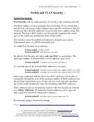
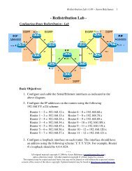
<strong>Multilayer</strong> <strong>Switching</strong> – <strong>Lab</strong> (continued)<br />
<strong>Multilayer</strong> <strong>Switching</strong> Objectives:<br />
<strong>Multilayer</strong> <strong>Switching</strong> <strong>Lab</strong> v1.00 – Aaron Balchunas<br />
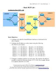
10. Reconfigure and cable the Ethernet interfaces on both the switch and router<br />
as indicated in the above final diagram. Ensure that VLANs 100 and 200<br />
are still created, and that switchport fa0/2 is assigned to VLAN 100, and<br />
switchport fa0/8 is assigned to VLAN 200.<br />
______________________________________________________________________<br />
______________________________________________________________________<br />
11. Configure multilayer switching as appropriate to route between VLAN 100<br />
and VLAN 200.<br />
______________________________________________________________________<br />
______________________________________________________________________<br />
______________________________________________________________________<br />
______________________________________________________________________<br />
______________________________________________________________________<br />
______________________________________________________________________<br />
______________________________________________________________________<br />
12. Configure PC 1’s and PC 2’s default gateways as appropriate to ensure<br />
connectivity.<br />
______________________________________________________________________<br />
______________________________________________________________________<br />
______________________________________________________________________<br />
______________________________________________________________________<br />
* * *<br />
All original material copyright © 2006 by Aaron Balchunas (aaron@routeralley.com),<br />
unless otherwise noted. All other material copyright © of their respective owners.<br />
This material may be copied and used freely, but may not be altered or sold without the expressed written consent<br />
of the owner of the above copyright. Updated material may be found at http://www.routeralley.com.<br />
4