DT-061 Details (PDF) - Donaldson Company, Inc.
DT-061 Details (PDF) - Donaldson Company, Inc.
DT-061 Details (PDF) - Donaldson Company, Inc.

Create successful ePaper yourself
Turn your PDF publications into a flip-book with our unique Google optimized e-Paper software.
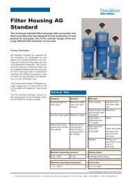
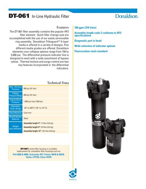
<strong>DT</strong>-<strong>061</strong> In-Line Hydraulic Filter<br />
Features<br />
The <strong>DT</strong>-<strong>061</strong> filter assembly contains the popular HF3<br />
filter element. Quick filter change outs are<br />
accomplished with the use of our easily serviceable<br />
ring assembly. <strong>Donaldson</strong> Triboguard TM 5-layer<br />
media is offered in a variety of designs. Five<br />
different media grades are offered. <strong>Donaldson</strong><br />
elements core collapse options range from 150 to<br />
3,000 psi. The differential pressure indicator line is<br />
designed to work with a wide assortment of bypass<br />
valves. Thermal lockout and surge control are two<br />
key features incorporated in the differential<br />
indicators.<br />
Max. Working<br />
Pressure<br />
Fatigue<br />
Pressure Rating<br />
Typical Burst<br />
Pressure<br />
600 psi (41 bar)<br />
600 psi (41 bar)<br />
1,500 psi max (100 bar)<br />
Operating<br />
Temp. Range -20° to 250°F (-29° to 121°C)<br />
Head Material Cast Iron<br />
Bowl & Notched<br />
Material<br />
Weight<br />
(w/o elements)<br />
Steel<br />
Assembly length 4”: 7.9 lbs (3,6 kg)<br />
Assembly length 8”: 8.9 lbs (4,0 kg)<br />
Assembly length 13”: 10.2 lbs (4,6 kg)<br />
Technical Data<br />
<strong>DT</strong>-<strong>061</strong> series filter housing is a suitable<br />
replacement for competitor filter housings such as:<br />
Pall 8600 & 8800, Schroeder RLT, Parker 40CN & 80CN,<br />
Hydac LPF330, Eaton HV3R<br />
100 gpm (379 l/min)<br />
Assembly length code 2 conforms to HF3<br />
specifications<br />
Diagnostic port in head<br />
Wide selection of indicator options<br />
Fluorocarbon seals standard
<strong>DT</strong>-<strong>061</strong> Performance Data<br />
Housing and Filter Element<br />
Flow versus Pressure Drop<br />
150 SUS (32 cst.) oil with specific gravity < 0.9<br />
PSID<br />
PSID<br />
PSID<br />
16<br />
12<br />
8<br />
4<br />
0<br />
0<br />
10<br />
Housing Only<br />
SAE 12 SAE 16<br />
20 30 40<br />
GPM<br />
50 60<br />
<strong>DT</strong>-9600-4<br />
LPM<br />
0<br />
20<br />
20 40 60<br />
2 µm<br />
80 100 120 140<br />
5 µm<br />
8 µm<br />
120<br />
15<br />
100<br />
14 µm<br />
80<br />
10<br />
25 µm<br />
60<br />
5<br />
40<br />
0<br />
0 10 20 30 40 0<br />
GPM<br />
0<br />
20<br />
50 100<br />
<strong>DT</strong>-9600-13<br />
LPM<br />
150 200 250 300 350<br />
15<br />
10<br />
5<br />
2 µm 5 µm<br />
8 µm<br />
14 µm<br />
80 100<br />
20<br />
0<br />
0 20 40 60 80 100 0<br />
GPM<br />
kPa<br />
120<br />
100<br />
80<br />
60<br />
40<br />
25 µm<br />
20<br />
kPa<br />
Viscosity Correction Formula<br />
ΔP Element = ΔP from curve x New Viscosity (SUS) x New Specific Gravity<br />
150 0.90<br />
ΔP Housing = ΔP from curve x New Specific Gravity<br />
0.90<br />
ΔP Assembly = ΔP Element + ΔP Housing<br />
PSID<br />
100<br />
PSID<br />
80<br />
60<br />
40<br />
20<br />
0<br />
0 25<br />
Bypass Valve<br />
50 PSID cracking<br />
25 PSID cracking<br />
50<br />
GPM<br />
75 100<br />
<strong>DT</strong>-9600-8<br />
LPM<br />
0 20 40 60 80 100 120 140 160 180<br />
20<br />
15<br />
10<br />
5<br />
2 µm<br />
5 µm<br />
8 µm<br />
14 µm<br />
25 µm<br />
0<br />
0 10 20 30 40 50 0<br />
GPM<br />
120<br />
100<br />
80<br />
60<br />
40<br />
20<br />
kPa
<strong>DT</strong>-<strong>061</strong> Ordering Code<br />
Length Construction<br />
1<br />
TABLE 1<br />
Housing Length<br />
1 4”<br />
2 8”<br />
3 13”<br />
TABLE 4<br />
Porting<br />
A SAE-12 O-Ring<br />
B SAE-16 O-Ring<br />
Example<br />
Model Housing Length Bypass Valve Indicator Porting Element Construction Micron Rating<br />
<strong>DT</strong>-<strong>061</strong> 3 A C B A 05<br />
TABLE 1 TABLE 2 TABLE 3 TABLE 4 TABLE 5 TABLE 6<br />
Select one option from each table below.<br />
(See example shown above.)<br />
TABLE 2<br />
Bypass Valve<br />
A No bypass<br />
B 50 psid bypass<br />
TABLE 5<br />
Element Construction<br />
A Standard (200 psid)<br />
Please note: Element<br />
selection to be ordered<br />
separately.<br />
Micron Rating<br />
Housing shipped without element.<br />
TABLE 3<br />
Indicator<br />
A Visual Indicator 35 psid<br />
C Visual/Electrical 35 psid<br />
N No indicator<br />
TABLE 6<br />
Micron Rating<br />
02 Beta 1,000 at < 4 micron<br />
05 Beta 1,000 at 5 micron<br />
08 Beta 1,000 at 8 micron<br />
14 Beta 1,000 at 14 micron<br />
25 Beta 1,000 at 25 micron<br />
02 05 08 14 25<br />
Element Chart<br />
<strong>DT</strong>-9600-4-2µm <strong>DT</strong>-9600-4-5µm <strong>DT</strong>-9600-4-8µm <strong>DT</strong>-9600-4-14µm <strong>DT</strong>-9600-4-25µm<br />
2 A<br />
<strong>DT</strong>-9600-8-2µm <strong>DT</strong>-9600-8-5µm <strong>DT</strong>-9600-8-8µm <strong>DT</strong>-9600-8-14µm <strong>DT</strong>-9600-8-25µm<br />
3 <strong>DT</strong>-9600-13-2µm <strong>DT</strong>-9600-13-5µm <strong>DT</strong>-9600-13-8µm <strong>DT</strong>-9600-13-14µm <strong>DT</strong>-9600-13-25µm
<strong>DT</strong>-<strong>061</strong> Components<br />
Differential Indicators<br />
Indicators are designed to actuate at approximately 80%<br />
of bypass valve cracking pressure. It is recommended<br />
that an indicator with a bypass setting of 35 psid is used<br />
with a non-bypass housing.<br />
Surge Control<br />
This optional feature is used to dampen pressure surges<br />
or spikes to avoid premature actuation of the indicator.<br />
Surge control delays the indicator response.<br />
Thermal Lockout<br />
Thermal Lockout (TL), prevents actuation below 60˚F and<br />
allows actuation above 100˚F system operating<br />
temperature. Its purpose is to avoid false actuations<br />
during periods of high fluid viscosity such as experienced<br />
during cold start.<br />
®<br />
Electric Indicator<br />
(Aluminum Housings)<br />
Schematic Wiring Diagram<br />
Note: The female plug (connector)<br />
is to be furnished by customer<br />
<strong>Donaldson</strong> <strong>Company</strong>, <strong>Inc</strong>.<br />
P.O. Box 1299<br />
Minneapolis, MN<br />
55440-1299 U.S.A.<br />
5/16-18UNC-3B Thd.<br />
Mounting Hole<br />
2 Plcs.<br />
Outlet Port<br />
57.15<br />
(2.25)<br />
38.1(1.50)Min. Required<br />
For Element And<br />
Bowl Removal<br />
29.97<br />
(1.18)<br />
28.45<br />
(1.12)<br />
26.92<br />
(1.06)<br />
185.42 (7.30)<br />
276.86 (10.90)<br />
396.24 (15.60)<br />
Tel 800.846.1846<br />
Fax 952.703.4913<br />
hydraulicfilters@mail.donaldson.com<br />
www.donaldson.com<br />
123.19<br />
(4.85)<br />
31.75<br />
(1.25)<br />
OUT IN<br />
34.80<br />
(1.37)<br />
63.50<br />
(2.50)<br />
33.53<br />
(1.32)<br />
P Indicator<br />
35.05 Max.<br />
(1.38)<br />
89.66 Max.<br />
(3.53)<br />
122.68 Max.<br />
(4.83)<br />
Bleed Plug<br />
7/16-20UNF<br />
SAE-4 Straight thd<br />
Torque: Hand Tight<br />
Visual 54.10 Max.<br />
(2.13)<br />
Elect. 65.53 Max.<br />
(2.58)<br />
Inlet Port<br />
Dimensions: millimeter(inch)<br />
Information in this document<br />
is subject to change without notice.<br />
© 2007 <strong>Donaldson</strong> Co., <strong>Inc</strong>.<br />
Printed in U.S.A. on recycled paper<br />
Bulletin No. HYD-502