Turbine Meter TRZ 03 Serving the Gas Industry Worldwide - rmg.com
Turbine Meter TRZ 03 Serving the Gas Industry Worldwide - rmg.com
Turbine Meter TRZ 03 Serving the Gas Industry Worldwide - rmg.com
You also want an ePaper? Increase the reach of your titles
YUMPU automatically turns print PDFs into web optimized ePapers that Google loves.
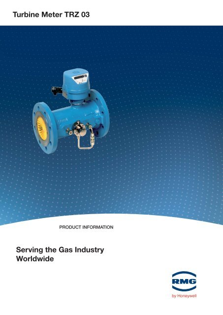
<strong>Turbine</strong> <strong>Meter</strong> <strong>TRZ</strong> <strong>03</strong><br />
PRODUCT INFORMATION<br />
<strong>Serving</strong> <strong>the</strong> <strong>Gas</strong> <strong>Industry</strong><br />
<strong>Worldwide</strong>
2<br />
TURBINE METER <strong>TRZ</strong> <strong>03</strong><br />
Methode of operation, Construction<br />
Methode of operation<br />
The <strong>TRZ</strong> <strong>03</strong> turbine meter is a fl ow meter suitable for gas<br />
measurement in <strong>com</strong>pliance with EN 12261 and OIML,<br />
where <strong>the</strong> rate of fl ow is indicated by a mechanical totalizer<br />
in units of volume (cubic meters at fl owing conditions)<br />
under prevailing pressure and temperature.<br />
The gas fl ow is constricted to a defi nite cross section and<br />
drives a coaxially mounted turbine wheel. The speed of<br />
<strong>the</strong> turbine wheel, which is proportional to <strong>the</strong> fl ow rate,<br />
is reduced by gearing and transmitted to <strong>the</strong> mechanical<br />
digital index.<br />
Construction<br />
The meter case <strong>com</strong>prises <strong>the</strong> measuring element with<br />
<strong>the</strong> turbine wheel. A fl ow straightener located upstream<br />
of <strong>the</strong> measuring element substantially eliminates turbulences<br />
and swirl from <strong>the</strong> gas fl ow and directs <strong>the</strong> gas<br />
onto <strong>the</strong> turbine blades.<br />
The rotary motion generated by <strong>the</strong> turbine wheel is<br />
transmitted by a magnetic coupling from <strong>the</strong> pressurized<br />
meter case to <strong>the</strong> unpressurized meter head.<br />
Flow straightener<br />
High-frequency<br />
pulse transmitter<br />
p connection<br />
r<br />
HF 3<br />
HF 1<br />
The number of rotations is reduced by gearing in <strong>the</strong><br />
meter head, which can be adjusted by selecting an<br />
appropriate pair of adjusting gears, so that cubic meters<br />
at fl owing<br />
conditions are indicated by <strong>the</strong> mechanical totalizer. A<br />
reed contact (or an inductive sensor) located on <strong>the</strong> mechanical<br />
totalizer provides low-frequency pulses whose<br />
number is proportional to <strong>the</strong> volume at actual conditions<br />
fl owed through.<br />
Inductive high-frequency sensors scan <strong>the</strong> turbine wheel<br />
(HF 3) and <strong>the</strong> reference wheel (HF 2). The latter is a cam<br />
wheel located on <strong>the</strong> same shaft as <strong>the</strong> turbine wheel<br />
which enables <strong>the</strong> turbine wheel to be monitored.<br />
In <strong>the</strong> <strong>TRZ</strong> <strong>03</strong>-E design, <strong>the</strong> gas meter operates without a<br />
meter head. This gas meter has only <strong>the</strong> electronic pulse<br />
transmitters HF 2 and HF 3 instead of <strong>the</strong> mechanical<br />
totalizer.<br />
Digital index Low-frequency<br />
pulse transmitter<br />
Magnetic coupling<br />
<strong>Turbine</strong> wheel<br />
HF 2<br />
LF<br />
Oil<br />
pump<br />
<strong>Meter</strong> head<br />
type "F"<br />
Thermowell<br />
Reference wheel<br />
High-frequency<br />
pulse transmitte
Features<br />
LF-Pulse transmitter (in <strong>the</strong> meter head)<br />
Standard: reed contact<br />
Alternatively : inductive pulse transmitter<br />
Option: up to 3 LF pulse transmitters<br />
possible<br />
HF-pulse transmitter (option)<br />
• In <strong>the</strong> meter head:<br />
Inductive pulse transmitter (HF 1), pulse frequency at<br />
Qmax approx. 100 Hz.<br />
• In <strong>the</strong> meter case:<br />
Inductive pulse transmitter for scanning<br />
- <strong>the</strong> blades of <strong>the</strong> turbine wheel<br />
(HF 3, from DN 80)<br />
- <strong>the</strong> cams of <strong>the</strong> reference wheel<br />
(HF 2, from DN 100)<br />
All inductive pulse transmitters provide volume pulses in<br />
<strong>com</strong>pliance with NAMUR.<br />
<strong>Meter</strong> head (type “F”)<br />
• protaction class IP 65<br />
• Universally readable<br />
• Totalizer unit and HF1 pulse transmitter are easily<br />
replaceable on site.<br />
Measuring range: up to 1:30<br />
With high-pressure testing, an expansion up to 1:50 is<br />
possible.<br />
Materials<br />
Rotor:<br />
Delrin for DN 50 to DN 200 and PN 10 / PN 16.<br />
Aluminium alloy for all o<strong>the</strong>r diameters and pressure<br />
ratings and for meters with HF sensors.<br />
Aluminium rotors instead of delrin rotors on special<br />
request.<br />
Nominal size: DN 50 through DN 600<br />
<strong>Meter</strong> case material (standard)<br />
Any material available on special request.<br />
TURBINE METER <strong>TRZ</strong> <strong>03</strong><br />
Features, Materials<br />
Pressure rating: PN 10 through PN 100,<br />
ANSI 150 through ANSI 600<br />
Special designs with a higher pressure rating are<br />
possible.<br />
Operating temperature range:<br />
Standard design: -10°C to +50°C<br />
Special designs for higher and/or lower temperatures<br />
are possible.<br />
Explosion protection<br />
The pulse transmitters are intrinsically safe; <strong>the</strong>ir type of<br />
protection is EEx ib IIC T6. Therefore, <strong>the</strong> <strong>TRZ</strong> <strong>03</strong> can be<br />
operated in Zone 1.<br />
Long service life<br />
pr-connection<br />
To connect <strong>the</strong> pressure transmitter of a PTZ corrector.<br />
Thermowell inside <strong>the</strong> meter case (option)<br />
To ac<strong>com</strong>modate a resistance <strong>the</strong>rmometer.<br />
Inspection report<br />
In <strong>com</strong>pliance with EN 10204/3.1B, for strength and<br />
leak testing.<br />
PN ANSI<br />
DN 10 16 25 40 64 100 150 300 600<br />
50<br />
80<br />
100<br />
150<br />
200<br />
250<br />
300<br />
400<br />
500<br />
600<br />
Steel Spheroidal cast iron<br />
Cast steel Steel, welded<br />
3
4<br />
TURBINE METER <strong>TRZ</strong> <strong>03</strong><br />
Accurancy, Approval, Pressure loss<br />
Accuracy<br />
Error limits (standard):<br />
±2.0% for Qmin to 0.2 Qmax<br />
±1.0% for 0.2 Qmax to Qmax<br />
These limits (calibration error limit) apply in <strong>the</strong> event of<br />
a steady, swirl-free fl ow. For an operating pressure above<br />
4 bar, half <strong>the</strong> calibration error limit is reached.<br />
Higher accuracy available on special request.<br />
Repeatability: ±0.1%<br />
All gas meters are tested in <strong>the</strong> factory with air under<br />
atmospheric pressure.<br />
Pressure loss<br />
The pressure loss Δp stated in <strong>the</strong> table applies to natural<br />
gas at Qmax and 1 bar. From this, <strong>the</strong> pressure loss at<br />
actual conditions can be calculated using <strong>the</strong> following<br />
formula:<br />
ρN QA<br />
2<br />
ΔpA = Δp · -------- · pA · ( ---------)<br />
0.83 Qmax<br />
ΔpA = Pressure loss at actual conditions (pA, QA) in mbar<br />
Δp = Pressure loss at Qmax with natural gas at 1 bar in<br />
mbar (see table)<br />
ρN = Standard density of <strong>the</strong> gas in kg/m3 pA = Operating pressure in bar (absolute)<br />
QA = Flow rate at actual conditions in m3 /h<br />
Qmax = Maximum fl ow rate in m3 /h (see table)<br />
Example:<br />
Air, ρN=1.29 kg/m 3 , nominal meter size DN 100,<br />
Qmax = 400 m 3 /h, pA=1.1 bar(a), QA=250 m 3 /h.<br />
Take from <strong>the</strong> table: Δp=4 mbar.<br />
Hence:<br />
1.29 250 2<br />
ΔpA = 4 · -------- · 1.1 · ( ---------) mbar = 2.7 mbar<br />
0.83 400<br />
Approvals<br />
The <strong>TRZ</strong> <strong>03</strong> turbine meter has been approved by PTB for<br />
custody transfer fl ow measurement and tested by DVGW.<br />
The reference numbers for approval are as follows:<br />
EU approval: D 81.7.211.10<br />
Domestic approval: 7.211/93.06<br />
DVGW product ident No.: CE-0085BN0291<br />
Nominal size<br />
DN<br />
Max. fl ow rate<br />
Qmax<br />
VLF*<br />
Δp<br />
HF-pulse transmitter<br />
(option)<br />
mm in. m 3 /h m 3 mbar HF2 HF3<br />
50 2“<br />
80 3“<br />
100 4“<br />
150 6“<br />
200 8“<br />
250 10“<br />
300 12“<br />
400 16“<br />
500 20“<br />
600 24“<br />
65<br />
100<br />
160<br />
250<br />
400<br />
250<br />
400<br />
650<br />
650<br />
1000<br />
1600<br />
1600<br />
2500<br />
1600<br />
2500<br />
4000<br />
4000<br />
6500<br />
6500<br />
10000<br />
10000<br />
16000<br />
16000<br />
25000<br />
0,1<br />
0,1<br />
1<br />
1<br />
1<br />
1<br />
1<br />
1<br />
1<br />
1<br />
10<br />
10<br />
10<br />
10<br />
10<br />
10<br />
10<br />
10<br />
10<br />
10<br />
10<br />
100<br />
100<br />
100<br />
3<br />
5 - -<br />
2<br />
6<br />
14<br />
2<br />
4<br />
10<br />
2<br />
6<br />
12<br />
3<br />
8<br />
2<br />
3<br />
7<br />
4<br />
9<br />
3<br />
8<br />
4<br />
9<br />
4<br />
9<br />
-<br />
•<br />
• •<br />
• •<br />
• •<br />
• •<br />
• •<br />
• •<br />
• •<br />
• •<br />
*VNF: volume at actuall con- - not available<br />
ditions per LF-pulse • available for all pressure<br />
classes
Types of gas<br />
The <strong>TRZ</strong> <strong>03</strong> standard design is suitable for use with all<br />
gases in <strong>com</strong>pliance with <strong>the</strong> DVGW code of practice<br />
G260. The materials used are appropriate for gases and<br />
fuel gases, such as natural gas, refi nery gas, gaseous<br />
liquid gases and <strong>the</strong>ir mixtures, nitrogen, CO2 (dry), air<br />
and all inert gases.<br />
For aggressive gases (e.g. biogas, acid gas or ethylene),<br />
<strong>the</strong>re are special designs available with PTFE lining, special<br />
material, special lubrication, etc.<br />
Mounting and operating instruction<br />
The <strong>TRZ</strong> <strong>03</strong> turbine meters can be operated in any mounting<br />
position up to <strong>the</strong> nominal size of DN 200. From <strong>the</strong><br />
nominal size of DN 250, <strong>the</strong>y can only be installed in a<br />
horizontal position.<br />
Special instructions for startup and operation:<br />
<strong>Turbine</strong> meters are precise measuring instruments and<br />
must <strong>the</strong>refore be carefully handled during transport,<br />
storage and operation.<br />
Do not fi ll any downstream pipelines or station sections<br />
via <strong>the</strong> turbine meter. This may result in excessive<br />
fl ow rates with resultant damage to <strong>the</strong> turbine<br />
wheel.<br />
The gas meter has been designed for short-term overload<br />
operation at up to 1.2 times <strong>the</strong> value of Qmax. Such load<br />
conditions should be avoided, however, in order to protect<br />
<strong>the</strong> <strong>TRZ</strong> <strong>03</strong> from any unnecessarily high fl ow rates.<br />
The gas fl ow must be free of shocks or pulsations, foreign<br />
particles, dust or liquids. O<strong>the</strong>rwise it is re<strong>com</strong>mended<br />
that fi lters and separators be installed.<br />
No <strong>com</strong>ponents aff ecting <strong>the</strong> gas fl ow are permitted<br />
directly upstream of <strong>the</strong> turbine meter (see DVGW guidelines<br />
and PTB guideline G 13).<br />
TURBINE METER <strong>TRZ</strong> <strong>03</strong><br />
Types of gas, Mounting and operating instruction<br />
2 DN<br />
1 DN<br />
Perforated-plate straightener<br />
In each case, an inlet pipe is required whose length as<br />
specifi ed in <strong>the</strong> type approval may be shorter than that<br />
specifi ed in <strong>the</strong> Technical Guideline G 13. The lengths<br />
of <strong>the</strong> inlet and outlet pipes must be at least 2 DN,<br />
while also a bend may be used as outlet pipe. If <strong>the</strong>re<br />
is a heavy fl ow perturbation (e.g. due to a gas pressure<br />
controller) upstream of <strong>the</strong> inlet pipe, it is additionally necessary<br />
to use a perforated-plate straightener. There are<br />
perforated-plate straighteners available <strong>com</strong>plying with<br />
ISO 5167-1 or of <strong>the</strong> type RMG LP-35, <strong>the</strong> latter resulting<br />
in a pressure loss which is 2.5 times lower than that of<br />
<strong>the</strong> standardized fl ow straightener.<br />
LP-35 perforated-plate straightener<br />
d<br />
d = e = 0.13 • DN<br />
Reducers or expansion fi ttings must be installed upstream<br />
of <strong>the</strong> inlet pipe and <strong>the</strong>ir opening angle must not<br />
exceed 30°.<br />
The gas meter must be installed in wea<strong>the</strong>rproof locations.<br />
For outside installations, appropriate guards must<br />
be provided against direct wea<strong>the</strong>ring infl uences.<br />
DN<br />
d<br />
<br />
e<br />
2 DN<br />
DN<br />
5
6<br />
TURBINE METER <strong>TRZ</strong> <strong>03</strong><br />
Pulse outputs, Maintenance, Order information<br />
Pulse outputs<br />
The meter head is fi tted with a reed contact as LF pulse<br />
transmitter as standard feature. But optionally, ano<strong>the</strong>r<br />
two sensors can be fi tted, e.g. ano<strong>the</strong>r LF pulse transmitter<br />
(inductive sensor with output pulses <strong>com</strong>plying with<br />
NAMUR or reed contact) and an HF1 pulse transmitter<br />
(NAMUR).<br />
Connection is made by means of a 7-pin Binder plug:<br />
5 +<br />
1, 4: LF (reed contact)<br />
2, 5: LF or HF 1signal<br />
3, 6: HF1 (NAMUR)<br />
If only one LF pulse transmitter is fi tted, it is always<br />
connected to <strong>the</strong> contacts 1 and 4; a single HF1 pulse<br />
transmitter is always connected to <strong>the</strong> contacts 3 and 6.<br />
If high-frequency pulse transmitters (with output pulses<br />
<strong>com</strong>plying with NAMUR) are fi tted which scan ei<strong>the</strong>r <strong>the</strong><br />
turbine wheel (HF3) or <strong>the</strong> reference wheel (HF2), each<br />
of <strong>the</strong>m is connected separately using a Binder plug at<br />
<strong>the</strong> front of <strong>the</strong> device:<br />
5<br />
6<br />
4<br />
4<br />
+<br />
6<br />
+<br />
+<br />
-<br />
-<br />
3<br />
-<br />
3<br />
-<br />
1<br />
1<br />
2<br />
2<br />
3, 6: HF2 or HF3signal<br />
The contacts 1, 2, 4 and 5 are not assigned.<br />
All pulse transmitters are intrinsically safe and may be<br />
connected only to certifi ed intrinsically safe circuits for<br />
use in areas subject to explosion hazards.<br />
Maximum pulse transmitter frequencies:<br />
LF: 0.3 Hz HF1: 300 Hz<br />
HF2: 2.1 kHz HF3: 2.1 kHz<br />
The phase displacement between <strong>the</strong> signals from <strong>the</strong><br />
HF2 and HF3 pulse transmitters is 180°.<br />
Maintenance<br />
All turbine meters are fi tted with a lubricator (DN 50<br />
through DN 150: permanent lubrication, from PN 25/<br />
ANSI 300 pushbutton pump; DN 200: pushbutton pump;<br />
from DN 250: lever pump).<br />
Lubrication must be performed in <strong>com</strong>pliance with <strong>the</strong><br />
operating instructions (see also <strong>the</strong> lubrication instruction<br />
plate of <strong>the</strong> gas meter). If clean gas is used, lubrication<br />
is to be performed at 3-month intervals, whereas<br />
lubrication must be performed more frequently if dust-<br />
and/or condensate-laden gas is used.<br />
Order information<br />
• Nominal size of <strong>the</strong> pipeline<br />
• Size G<br />
• Operating pressure (min/max) in bar g or bar a<br />
• Operating temperature (min/max)<br />
• Ambient temperature (min/max)<br />
• Type of gas to be used<br />
• Pressure rating and DIN or ANSI fl ange design<br />
• Direction of fl ow / mounting position<br />
• Accessories: inlet section, volume corrector, etc.<br />
• Options: HF pulse outputs, etc.<br />
• Special designs, e.g. for aggressive gases
Measuring ranges, dimensions, weights<br />
DN<br />
mm<br />
Sizes<br />
Measuring range<br />
(m 3 /h)<br />
Approx. weight (kg)<br />
pressure rating<br />
TURBINE METER <strong>TRZ</strong> <strong>03</strong><br />
Dimensions<br />
mm<br />
in. Qmin Qmax PN ANSI<br />
1:20 1:30 10 16 25 40 64 100 150 300 600 H C L<br />
50<br />
2”<br />
80<br />
3"<br />
100<br />
4"<br />
150<br />
6"<br />
200<br />
8"<br />
250<br />
10"<br />
300<br />
12"<br />
400<br />
16"<br />
500<br />
20"<br />
600<br />
24"<br />
G 65 10 1) - 100 13 13 21 21 21 21 13 13 21 2) 210 60 150<br />
G 100<br />
G 160<br />
G 250<br />
G 160<br />
G 250<br />
G 400<br />
G 400<br />
G 650<br />
G 1000<br />
G 1000<br />
G 1600<br />
G 1000<br />
G 1600<br />
G 2500<br />
G 2500<br />
G 4000<br />
G 4000<br />
G 6500<br />
G 6500<br />
G 10000<br />
G 10000<br />
G 16000<br />
16 1)<br />
13<br />
20<br />
13<br />
20<br />
32<br />
32<br />
50<br />
80<br />
80<br />
130<br />
80<br />
130<br />
200<br />
200<br />
320<br />
320<br />
500<br />
500<br />
800<br />
800<br />
1300<br />
1) Measuring range 1:10<br />
2) Мonofl ange design<br />
-<br />
-<br />
-<br />
-<br />
-<br />
20<br />
-<br />
32<br />
50<br />
50<br />
80<br />
-<br />
80<br />
130<br />
130<br />
200<br />
200<br />
320<br />
320<br />
500<br />
500<br />
800<br />
160<br />
250<br />
400<br />
250<br />
400<br />
650<br />
650<br />
1000<br />
1600<br />
1600<br />
2500<br />
1600<br />
2500<br />
4000<br />
4000<br />
6500<br />
6500<br />
10000<br />
10000<br />
16000<br />
16000<br />
25000<br />
From DN 80 to DN 300, <strong>the</strong> turbine meters with a<br />
pressure rating of PN 10/16 can be fi tted with a<br />
<strong>the</strong>rmowell to ac<strong>com</strong>modate a temperature sensor.<br />
20 20 25 25 34 34 20 25 36 230 96 240<br />
25 25 32 32 45 45 30 35 55 270 120 300<br />
50 50 60 60 70 90 50 65 100 285 180 450<br />
75 75 95 95 150 160 100 120 160 320 240 600<br />
100 110 135 150 180 225 110 160 260 330 300 750<br />
138 150 225 265 275 290 155 230 310 360 360 900<br />
280 290 350 440 525 580 350 460 575 400 480 1200<br />
560 610 640 700 830 1060 620 650 1075 450 600 1500<br />
900 940 980 1075 1230 1570 950 1000 1600 500 720 1800<br />
H<br />
Measuring ranges, dimensions, weights<br />
L<br />
C<br />
DN<br />
7
For More Information<br />
To learn more about RMG´s advanced gas<br />
solutions, contact your RMG<br />
account manager or visit<br />
www.<strong>rmg</strong>.<strong>com</strong><br />
GERMANY<br />
Honeywell Process Solutions<br />
RMG Regel + Messtechnik GmbH<br />
Osterholzstrasse 45<br />
34123 Kassel, Germany<br />
Tel: +49 (0)561 5007-0<br />
Fax: +49 (0)561 5007-107<br />
Honeywell Process Solutions<br />
RMG Messtechnik GmbH<br />
Otto-Hahn-Strasse 5<br />
35510 Butzbach, Germany<br />
Tel: +49 (0)6<strong>03</strong>3 897-0<br />
Fax: +49 (0)6<strong>03</strong>3 897-130<br />
Honeywell Process Solutions<br />
RMG <strong>Gas</strong>elan Regel + Messtechnik GmbH<br />
Julius-Pintsch-Ring 3<br />
15517 Fürstenwalde, Germany<br />
Tel: +49 (0)3361 356-60<br />
Fax: +49 (0)3361 356-836<br />
Honeywell Process Solutions<br />
WÄGA Wärme-<strong>Gas</strong>technik GmbH<br />
Osterholzstrasse 45<br />
34123 Kassel, Germany<br />
Tel: +49 (0)561 5007-0<br />
Fax: +49 (0)561 5007-207<br />
POLAND<br />
Honeywell Process Solutions<br />
Gazomet Sp. z o.o.<br />
ul. Sarnowska 2<br />
63-900 Rawicz, Poland<br />
Tel: +48 (0)65 5462401<br />
Fax: +48 (0)65 5462408<br />
ENGLAND<br />
Honeywell Process Solutions<br />
Bryan Donkin RMG <strong>Gas</strong> Controls Ltd.<br />
Enterprise Drive, Holmewood<br />
Chesterfi eld S42 5UZ, England<br />
Tel: +44 (0)1246 501-501<br />
Fax: +44 (0)1246 501-500<br />
CANADA<br />
Honeywell Process Solutions<br />
Bryan Donkin RMG Canada Ltd.<br />
50 Clarke Street South, Woodstock<br />
Ontario N4S 0A8, Canada<br />
Tel: +1 (0)519 5398531<br />
Fax: +1 (0)519 5373339<br />
USA<br />
Honeywell Process Solutions<br />
Mercury Instruments LLC<br />
3940 Virginia Avenue<br />
Cincinnati, Ohio 45227, USA<br />
Tel: +1 (0)513 272-1111<br />
Fax: +1 (0)513 272-0211<br />
TURKEY<br />
Honeywell Process Solutions<br />
RMG GAZ KONT. SIS. ITH. IHR. LTD. STI.<br />
Birlik Sanayi Sitesi, 6.<br />
Cd. 62. Sokak No: 7-8-9-10<br />
TR - Sasmaz / Ankara, Turkey<br />
Tel: +90 (0)312 27810-80<br />
Fax: +90 (0)312 27828-23<br />
<strong>TRZ</strong> <strong>03</strong><br />
2010-06<br />
© 2010 Honeywell International Inc.


