Valve Springs - Crane Cams
Valve Springs - Crane Cams
Valve Springs - Crane Cams

Create successful ePaper yourself
Turn your PDF publications into a flip-book with our unique Google optimized e-Paper software.
VALVE TRAIN<br />
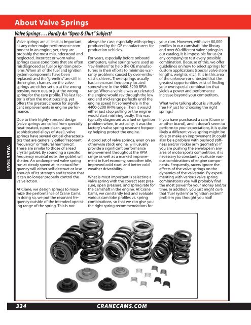
About <strong>Valve</strong> <strong>Springs</strong><br />
<strong>Valve</strong> <strong>Springs</strong> . . . Hardly An “Open & Shut” Subject!<br />
<strong>Valve</strong> springs are at least as important<br />
as any other major performance component<br />
in an engine; yet, they are<br />
probably the most misunderstood and<br />
neglected. Incorrect or worn valve<br />
springs cause conditions that are often<br />
misdiagnosed as fuel or ignition problems.<br />
When all of the fuel and ignition<br />
system components have been<br />
replaced; and the “gremlins” are still in<br />
the engine, chances are the valve<br />
springs are either set up at the wrong<br />
tension, worn out, or just the wrong<br />
spring for the cam profile. This last factor<br />
is often the most puzzling, yet<br />
offers the greatest chance for significant<br />
improvements in engine performance.<br />
Due to their highly stressed design<br />
(valve springs are coiled from specially<br />
heat-treated, super-clean, supersophisticated<br />
alloys of steel), valve<br />
springs have several critical characteristics<br />
that are generally called “resonant<br />
frequency” or “natural harmonics”.<br />
These are similar to those of a lead<br />
crystal goblet. By sounding a specific<br />
frequency musical note, the goblet will<br />
shatter. An undampened valve spring<br />
run at steady speed at its natural frequency<br />
will either self-destruct or lose<br />
enough of its strength and tension that<br />
it can no longer properly control the<br />
valve action.<br />
At <strong>Crane</strong>, we design springs to maximize<br />
the performance of <strong>Crane</strong> <strong>Cams</strong>.<br />
In doing so, we put the resonant frequency<br />
outside of the intended operating<br />
range of the spring. This is not<br />
334<br />
always the case, especially with springs<br />
produced by the OE manufacturers for<br />
production vehicles.<br />
For years, especially before onboard<br />
computers, valve springs were used as<br />
“rev-limiters” to help the OE manufacturers<br />
in their efforts to minimize warranty<br />
problems caused by over-enthusiastic<br />
drivers. These springs usually<br />
had a resonant frequency located<br />
somewhere in the 4400-5200 RPM<br />
range. When a vehicle was accelerated,<br />
the engine would rev through the low<br />
end and mid-range perfectly until the<br />
engine speed hit somewhere in the<br />
4400-5200 RPM range. Then it would<br />
either just stop pulling or the engine<br />
would start misfiring badly. This was<br />
typically diagnosed as a fuel or ignition<br />
problem when, in actuality, it was the<br />
factory’s valve spring resonant frequency<br />
helping protect the engine.<br />
A good set of valve springs, even on an<br />
otherwise stock engine, will usually<br />
provide a significant performance<br />
improvement throughout the RPM<br />
range as well as a marked improvement<br />
in fuel economy, smoother idle,<br />
improved cold start, and better cold<br />
weather driveability.<br />
What is most important is selecting a<br />
valve spring with the correct seat pressure,<br />
open pressure, and spring rate for<br />
the camshaft in the engine. At <strong>Crane</strong><br />
<strong>Cams</strong>, we constantly test and evaluate<br />
various cam lobe profiles vs. spring<br />
combinations, so that we can give you<br />
the right spring recommendations for<br />
CRANECAMS.COM<br />
your cam. However, with over 80,000<br />
profiles in our camshaft lobe library<br />
and over 60 different valve springs in<br />
our catalog, it is impossible for us (or<br />
any company) to test every possible<br />
combination. Because of this, we offer<br />
guidelines on how to select springs for<br />
custom applications (special valve stem<br />
lengths, weights, etc.). It is in this area<br />
of the unknown or untested that the<br />
greatest opportunities exist of finding<br />
your own special combination that<br />
yields a power and performance<br />
increase beyond your competitors.<br />
What we’re talking about is virtually<br />
free HP just for choosing the right<br />
springs!<br />
If you have purchased a cam (<strong>Crane</strong> or<br />
another brand), and it doesn’t seem to<br />
perform to your expectations, it is quite<br />
likely a different valve spring might be<br />
able to make an improvement (It could<br />
also be a problem with pushrod stiffness<br />
and/or rocker arm geometry.) If<br />
you are pushing the envelope in any<br />
area of motorsports competition, it is<br />
necessary to constantly evaluate various<br />
combinations of engine components.<br />
Frequently, racers ignore the<br />
effects of the valve springs on the<br />
dynamics of the valvetrain. By experimenting<br />
with various valve spring<br />
combinations you will probably find<br />
the most power for your money and/or<br />
time. In addition, you just might cure<br />
that “fuel system” or “ignition system”<br />
problem you thought you had!
<strong>Valve</strong> Train Questions<br />
<strong>Valve</strong> Spring Rate and How to Use It<br />
The rate of a spring is the force necessary<br />
to compress (or deflect) the spring<br />
a specified distance. For example, if we<br />
say that a spring has a rate of 250 lbs.<br />
per inch (250#/in.), it will take 250<br />
pounds of force to compress the spring<br />
1 inch. Fortunately, valve springs are<br />
coil springs, and coil springs are easy to<br />
understand because they have an<br />
almost linear spring rate. In other<br />
words, if it takes 400 lbs. to compress a<br />
spring 1 inch, it only takes 100 lbs. to<br />
compress the spring .250 in., 200 lbs. to<br />
compress it .500 in., and 300 lbs. to<br />
compress it .750 in. Some people refer<br />
to spring rate as “stiffness”, and it is the<br />
understanding of this spring characteristic<br />
that is most important in selecting<br />
and setting up springs on an automotive<br />
cylinder head.<br />
Frequently a taller, softer spring is a<br />
better choice for a performance application<br />
than a short, stiff spring.<br />
Consider the following possibility:<br />
A vehicle owner wants to use a .520" valve lift camshaft in an application<br />
and is considering different valve springs.<br />
Spring A has an installed pressure of 125# at 1.750" installed height and has<br />
a rate of 280#/in.<br />
Spring B has an installed pressure of 115# at 1.750" installed height with a<br />
rate of 410#/in.<br />
At .520" lift, Spring A has an open pressure of 271# (this is 125# of seat pressure<br />
plus [.520" x 280#/in] = 146# from spring compression). At .520" lift,<br />
Spring B has an open pressure of 328# (this is 115# of seat pressure plus<br />
[.520" x 410#/in] = 213# from spring compression). Both of these springs<br />
would work on a street performance application requiring good performance<br />
and reliability. However, Spring A with a lower open pressure of<br />
271# could probably be used on a cylinder head with pressed in rocker<br />
studs; while Spring B would definitely require screw in studs for adequate<br />
reliability. Spring B would probably provide better performance above 6000<br />
RPM (especially with relatively heavy valves) because of its higher open<br />
pressure of 328#. Spring A would probably idle a little smoother with higher<br />
vacuum, especially if a high pressure oil pump or thicker oil is used. This is<br />
a result of Spring A's higher seat pressure of 125#.<br />
As you can see from the example above, there are often different springs that can offer different benefits on the same cam<br />
profile. Spring A offers good performance over a wide RPM range at a lower total valvetrain cost (this assumes that the<br />
heads were not machined for screw in studs). Spring B offers the possibility of somewhat improved performance beyond<br />
6000 RPM. The vehicle owner needs to decide what he wants from his vehicle and what he wants to spend.<br />
In all-out racing, we frequently see the need for different springs on the same lobe profile depending on the anticipated<br />
RPM range. Frequently, circle track racers will run two different tracks with the same engine but with different rear end<br />
gearing. Often there can be as much as 500-700 RPM difference in the top end engine speed between the two tracks. It is<br />
not uncommon to find that the car runs better on the track with the lower peak RPM using a spring with a lower seat pressure<br />
and softer rate. At the track where the engine runs to the higher speed, the engine needs more seat pressure and a<br />
stiffer spring rate. Every combination of engine, chassis, and track is different. Significant performance improvements can<br />
often be achieved by experimenting with valve springs. If you aren’t paying attention to your springs, the guy winning<br />
most of the races probably is!<br />
866-388-5120 • 386-236-9983 FAX 335
VALVE TRAIN<br />
Choosing <strong>Valve</strong> <strong>Springs</strong><br />
How to Select a <strong>Valve</strong> Spring<br />
With the many choices of aftermarket cylinder heads, most with longer-than-stock length valves, the recommendation of a<br />
specific spring for a specific cam is almost impossible. It is now necessary to select the spring that will best fit the cylinder<br />
head configuration. We offer the following as general guidelines only:<br />
1) “FLAT FACED LIFTER” cam/lifter applications (Street & Street/Strip) seat pressures<br />
336<br />
a. Small Block: 105-125# Seat Pressure<br />
b. Big Block: 115-130# Seat Pressure (Note: Big Block applications need higher seat pressures due to their<br />
larger, heavier valves.)<br />
2) “FLAT FACED LIFTER” Open pressures should not exceed 330# open pressure (sustained after spring break-in<br />
for accepable cam and lifter life.<br />
a. Open pressures should be a minimum of 220# for applications up to 4000 RPM.<br />
b. For good performance above 4000, open pressures should be at least 260# with stock weight valves.<br />
(Lightweight valves require less spring open pressure.)<br />
c. Spring open pressures over 280# can cause pressed-in studs to come loose; therefore, we recommend<br />
screw-in studs for open pressures above 280#.<br />
3) HYDRAULIC ROLLER CAMS require higher spring seat pressures to control the heavier roller tappets and the more<br />
aggressive opening and closing rates available to roller cam profiles.<br />
a. Small Block applications: 120-145# seat pressure<br />
b. Big Block applications: 130-165# seat pressure<br />
4) HYDRAULIC ROLLER CAMS use higher open pressures to control the high vertical opening inertia of the heavier<br />
roller followers.<br />
a. Small Block applications need at least 260# for general driving applications up to 4000 RPM.<br />
b. Moderate performance small block applications like 300-360# open.<br />
c. Serious small block applications can tolerate 400-425#* open pressures and still expect reasonable<br />
valve train life when top quality springs, pushrods, and lubricants are used.<br />
d. Big Block applications need at least 280# for general driving applications up to 4000 RPM.<br />
e. Moderate performance big block applications like 325-375# open pressure.<br />
f. Serious big block performance applications can tolerate 450#* open pressure and still expect<br />
reasonable valve train life when top quality springs, pushrods, and lubricants are used.<br />
*Note: Open pressures in excess of 360# require the use of roller tappet bodies made of billet steel. <strong>Crane</strong> hydraulic roller<br />
and solid roller tappets are made from heat treated steel billet to withstand the stresses of high-performance use. Most<br />
stock hydraulic roller tappet bodies are made of cast iron and cannot tolerate high spring loads.<br />
5) MECHANICAL ROLLER CAM/LIFTER<br />
Applications are generally for serious street/strip use and full competition. Most are not used in daily-drivers where<br />
day-to-day reliability is stressed. Instead, most of these cams are intended for winning performance. These cams are<br />
designed with very aggressive opening and closing rates. High seat pressures are necessary to keep the valves from<br />
bouncing when they come back to the seat. In all cases, the valve action and spring pressures required mandate the<br />
use of high-strength, one-piece valves. However, <strong>Crane</strong> does offer the SR-Series of Street Roller camshafts intended<br />
for daily usage.<br />
a. Seat Pressures are determined by valve/retainer weight, engine RPM and life expectancy of components<br />
before replacement is required. Milder roller cams require 165# on the seat as an absolute minimum.<br />
180-200# is common for most modest performance applications. 220-250# is common for most serious<br />
sport categories and some circle track professional categories. Pro-Stock and Blown Alcohol/Fuel drag<br />
applications use as much as 340-500# on the seat.<br />
b. Open Pressures need to be high enough to control the valvetrain as the lifter goes over the nose of the cam.<br />
Ideally, the minimum amount of open pressure to eliminate or minimize valvetrain separation is desired. Any<br />
excess open pressure only contributes to pushrod flex, which can aggravate valvetrain separation. For serious<br />
racing applications this can be determined only by experimentation and track testing. For general guidelines<br />
we offer the following<br />
i. Street/Strip performance with long cam/lifter life desirable, 350-450# open.<br />
ii. Circle track and moderate bracket racing 450-600@ open.<br />
iii. Serious drag racing and limited distance circle track racing 600# and more.<br />
CRANECAMS.COM
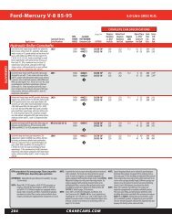
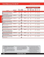
<strong>Valve</strong> <strong>Springs</strong><br />
O.D I.D.1 I.D.2 Damper Seat Press. Open Press. Coil Bind<br />
Dual <strong>Valve</strong> <strong>Springs</strong><br />
Max Net Lift<br />
w /.060”<br />
clearance<br />
1.555 1.130 0.743 Yes 256 lbs @ 2.000 652 @ 1.250 1.178 0.762 510 lbs/in.<br />
1.565 1.146 0.740 Yes 190 lbs @ 1.950 552 @ 1.250 1.200 0.690 504 lbs/in.<br />
1.565 1.129 0.749 Yes 215 lbs @ 1.950 685 @ 1.200 1.121 0.769 618 lbs/in.<br />
1.593 1.154 0.741 Yes 254 lbs @ 2.050 687 @ 1.280 1.220 0.780 576 lbs/in.<br />
1.625 1.175 0.851 No 280 lbs @ 2.100 847 @ 2.100 1.100 0.900 629 lbs/in.<br />
1.625 1.175 0.769 Yes 244 lbs @ 2.000 801 @ 1.150 1.090 0.850 656 lbs/in.<br />
1.625 1.175 0.769 Yes 250 lbs @ 2.050 673 @ 1.300 1.210 0.750 564 lbs/in.<br />
1.625 1.175 0.851 No 275 lbs @ 2.000 810 @ 1.150 1.100 0.850 625 lbs/in.<br />
Rate<br />
(lbs/in.) Application Part No.<br />
Professional roller cam race applications<br />
Electro-Polished 96884-16<br />
Solid street rollers/Bracket racing; Hi Perf big<br />
block hyd rlrs w/tall assy hts. 99876-16<br />
Bracket Race & Circle Track Roller <strong>Cams</strong><br />
XHTCS Spring 99885-16<br />
Professional circle track endurance, ID<br />
chamfered coils, radiused damper ends, PAC<br />
enhanced wire. 96885-16<br />
Bracket Race applications with hight lift /<br />
agressive valve train and RPM requirements,<br />
Pacaloy wire. 961228-16<br />
Drag Race roller cams with approx. 2.00” inst<br />
hts. XHTCS 99880-16<br />
Various Big Block roller camshafts, lower lift<br />
bracket racing, PAC enhanced wire. 961299-16<br />
Various Big Block roller camshafts, high lift<br />
bracket racing, PAC enhanced wire. 961224-16<br />
Triple <strong>Valve</strong> <strong>Springs</strong><br />
1.645 1.195 0.635 No 250 lbs @ 2.050 801 @ 1.250 1.130 0.800 689 lbs/in.<br />
Various Big Block roller camshafts, high lift<br />
bracket racing, PAC enhanced wire.<br />
Various Big Block roller camshafts, high lift<br />
bracket racing, Nano-Peened, PAC enhanced<br />
961246-16<br />
1.645 1.195 0.635 No 290 lbs @ 2.070 835 @ 1.270 1.130 0.800 682 lbs/in. wire.<br />
Various Big Block roller camshafts, high lift<br />
bracket racing, Nano-Peened, PAC enhanced<br />
961347-16<br />
1.645 1.195 0.635 No 332 lbs @ 2.100 950 @ 1.200 1.130 0.900 688 lbs/in. wire.<br />
Various Big Block roller camshafts, high lift<br />
961348-16<br />
1.667 1.195 0.635 No 300 lbs @ 2.100 963 @ 1.250 1.135 0.850 780 lbs/in. bracket racing, PAC enhanced wire. 96888-16<br />
1.675 1.203 0.634 No 362 lbs @ 2.100 1035 @ 1.200 1.161 0.879 684 lbs/in. Pro Drag Racing including blown alcohol & fuel 96848-16<br />
1.675 1.203 0.634 No 352 lbs @ 2.200 1024 @ 1.200 1.161 0.979 690 lbs/in. Pro Drag Racing including blown alcohol & fuel 96849-16<br />
More <strong>Valve</strong> Train Questions<br />
What is <strong>Valve</strong> Spring Coil Bind and how does it relate to Spring Travel and <strong>Valve</strong> Lift?<br />
When the valve spring is compressed until its coils touch one another and can travel no further, it is said to be in coil bind.<br />
The catalog (pages 337 to 339) shows the approximate coil bind height for the various <strong>Crane</strong> <strong>Cams</strong> valve springs. To measure<br />
this you must install the retainer in the valve spring, then compress the spring until it coil binds. Now measure from<br />
the bottom side of the retainer to the bottom of the spring. This measurment is the coil bind height. (See Figure 1) This can<br />
be done on the cylinder head with a spring compression tool in a bench vise, or in a professional valve spring tester.<br />
Using Figure 1, subtract the coil bind height “B” from the valve spring installed height “A”. The difference “C” is the maximum<br />
spring travel. The spring travel is usually at least .060” greater than the full lift of the valve. This safety margin of .060”<br />
(or more) is necessary to avoid the dangers of coil bind and over-stressing the spring.<br />
If coil bind occurs, the resulting mechanical interference will severely damage the camshaft and valvetrain components.<br />
INSTALLED<br />
HEIGHT<br />
A<br />
C<br />
B<br />
COIL<br />
BIND<br />
HEIGHT<br />
Figure 1<br />
866-388-5120 • 386-236-9983 FAX 339
<strong>Valve</strong> <strong>Springs</strong><br />
<strong>Valve</strong> Spring Spec Chart<br />
Spring Type Dual Dual Dual Triple Triple Triple Triple Triple Triple<br />
O.D. 1.625 1.625 1.625 1.675 1.675 1.645 1.645 1.645 1.667<br />
I.D. 0.769 0.769 0.851 0.634 0.634 0.635 0.635 0.635 0.635<br />
Damper Yes Yes No No No No No No No<br />
Installed Height 2.000 2.050 2.000 2.100 2.200 2.050 2.070 2.100 2.100<br />
Coil Bind 1.090 1.210 1.100 1.161 1.161 1.130 1.130 1.135 1.135<br />
Spring Rate (lbs/in.) 656 564 625 684 690 689 682 688 780<br />
Max. Net. Lift 0.850 0.750 0.850 0.879 0.979 0.800 0.800 0.900 0.850<br />
Part No. 99880 961299 961224 96848 96849 961246 961347 961348 96888<br />
2.300 230 289<br />
2.250 262 320<br />
2.200 295 352 263<br />
2.150 194 329 385 236 298 261<br />
2.100 182 222 212 362 418 216 270 332 300<br />
2.050 213 250 244 396 452 250 304 366 339<br />
2.000 244 278 275 430 487 284 338 401 378<br />
1.950 275 306 306 462 520 319 372 435 417<br />
1.900 306 335 338 498 554 353 406 469 456<br />
1.850 337 363 369 530 588 388 440 504 495<br />
1.800 368 391 401 564 623 422 474 538 534<br />
1.750 400 419 432 598 657 457 508 572 573<br />
1.700 431 447 464 633 692 491 542 607 612<br />
1.650 463 476 495 668 727 526 576 641 651<br />
1.600 496 504 527 704 761 560 610 675 690<br />
1.550 528 532 558 740 797 594 644 710 729<br />
1.500 560 560 590 776 832 629 678 744 768<br />
1.450 594 588 621 815 870 663 712 778 807<br />
1.400 627 617 653 857 906 698 746 813 846<br />
1.350 663 645 684 900 942 732 781 847 885<br />
1.300 696 673 716 942 981 767 815 881 924<br />
1.250 731 701 747 987 1024 801 849 916 963<br />
1.200 764 779 1035 835 883 950 1002<br />
1.150 801 810 984<br />
1.100<br />
1.050<br />
1.000<br />
0.950<br />
0.900<br />
Popular Recommended Components<br />
Steel Retainers<br />
(see page 350)<br />
Titanium Retainers 7 o<br />
(see page 351)<br />
Titanium Retainers 10 o<br />
(see page 351)<br />
Spring Seats<br />
(see page 362)<br />
* Denotes Inner Spring<br />
99962<br />
BOLD Numbers are recommended closed pressures @ installed height.<br />
99675 99660 99660 99678 99678 99662 99662 99662 99678<br />
99681 99681<br />
99681<br />
99633 99638 99638 99632 99632<br />
99632<br />
99636 99636<br />
99636<br />
99466 99466 99463 99461 99461 99461<br />
99463 99463<br />
866-388-5120 • 386-236-9983 FAX 347