Product Data
Product Data
Product Data

Create successful ePaper yourself
Turn your PDF publications into a flip-book with our unique Google optimized e-Paper software.
<strong>Product</strong><br />
<strong>Data</strong><br />
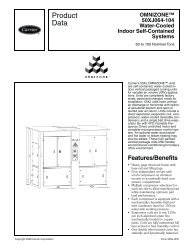
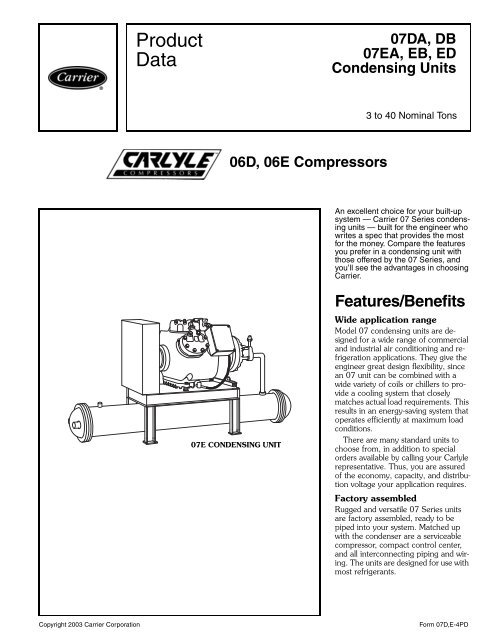
06D, 06E Compressors<br />
07E CONDENSING UNIT<br />
07DA, DB<br />
07EA, EB, ED<br />
Condensing Units<br />
3 to 40 Nominal Tons<br />
An excellent choice for your built-up<br />
system — Carrier 07 Series condensing<br />
units — built for the engineer who<br />
writes a spec that provides the most<br />
for the money. Compare the features<br />
you prefer in a condensing unit with<br />
those offered by the 07 Series, and<br />
you’ll see the advantages in choosing<br />
Carrier.<br />
Features/Benefits<br />
Wide application range<br />
Model 07 condensing units are designed<br />
for a wide range of commercial<br />
and industrial air conditioning and refrigeration<br />
applications. They give the<br />
engineer great design flexibility, since<br />
an 07 unit can be combined with a<br />
wide variety of coils or chillers to provide<br />
a cooling system that closely<br />
matches actual load requirements. This<br />
results in an energy-saving system that<br />
operates efficiently at maximum load<br />
conditions.<br />
There are many standard units to<br />
choose from, in addition to special<br />
orders available by calling your Carlyle<br />
representative. Thus, you are assured<br />
of the economy, capacity, and distribution<br />
voltage your application requires.<br />
Factory assembled<br />
Rugged and versatile 07 Series units<br />
are factory assembled, ready to be<br />
piped into your system. Matched up<br />
with the condenser are a serviceable<br />
compressor, compact control center,<br />
and all interconnecting piping and wiring.<br />
The units are designed for use with<br />
most refrigerants.<br />
Copyright 2003 Carrier Corporation Form 07D,E-4PD
Features/Benefits (cont)<br />
The benefits are many<br />
• fully assembled units<br />
• capacities to 40 tons<br />
• system design flexibility<br />
• commercial and industrial<br />
application<br />
• for use with most refrigerants<br />
• special-order combinations available<br />
on request<br />
Accurate system design<br />
Broad range of sizes allows selection<br />
of evaporator coil or chiller to<br />
form a well-balanced system. Capacity<br />
will closely match the system load requirements,<br />
and provide efficient,<br />
energy-saving, economical operation<br />
at maximum load conditions.<br />
A unit for all load conditions is<br />
offered, from refrigeration to air<br />
conditioning duty. Units have shelland-tube<br />
condensers. All are compactly<br />
designed to take minimum floor<br />
space. The 07 Series units are built<br />
and tested to comply with ASME<br />
(American Society of Mechanical<br />
Engineers) Code for unfired pressure<br />
vessels, and ANSI/ASHRAE 15<br />
(American National Standards<br />
Institute/American Society of Heating,<br />
Refrigeration and Air Conditioning<br />
Engineers) latest revision safety<br />
standard.<br />
2<br />
Economical operation<br />
Capacity control valves are provided<br />
in all 07 Series units, except<br />
07DA203 models, giving a built-in<br />
system for conserving power and water<br />
and assuring accurate control. When<br />
only partial load operation is needed,<br />
capacity control valves automatically<br />
step down compressor capacity. Refrigeration<br />
output can be reduced to<br />
about one third of full load in direct response<br />
to suction pressure changes.<br />
When system load is reduced, power<br />
and water usage are also reduced. Suction<br />
cutoff unloading further reduces<br />
energy usage during unloaded operation.<br />
Valve body shuts off passage from<br />
suction manifold, preventing charge<br />
from unnecessarily being pulled into<br />
the cylinder. This results in an EER<br />
(Energy Efficiency Ratio) improvement<br />
of as much as 39.5% at 33% load.<br />
Built-in reliability<br />
Condenser includes a pressure relief<br />
device which protects the system<br />
against overpressure.<br />
Compressor has motor overtemperature<br />
protection. On 07E models,<br />
manually reset 3-phase circuit breakers<br />
protect against power irregularities.<br />
High- and low-pressure switches are<br />
standard. Oil-pressure switch is<br />
standard on 07D and 07E models. An<br />
automatically reversible oil pump with<br />
automatic pressure regulator keeps<br />
07D CONDENSING UNIT 07E CONDENSING UNIT<br />
bearings properly lubricated. Crankcase<br />
heater keeps oil warm and prevents<br />
dilution of oil by refrigerant<br />
during shutdown. Time Guard circuit<br />
prevents short cycling by compressor.<br />
After shutdown, the timing device<br />
delays compressor start-up for approximately<br />
5 minutes. This reduces wear<br />
and extends compressor life. Compressor<br />
motor is sealed against dirt and<br />
moisture and is cooled by suction gas.<br />
It eliminates drive shaft alignment and<br />
shaft seal problems.<br />
Noise and vibration control<br />
Muffler in discharge line minimizes<br />
sound level.<br />
Compressor is mounted on spring<br />
isolators to minimize transfer of<br />
vibration from compressor to base<br />
structure.<br />
Low-cost maintenance<br />
Condenser heads are removable for<br />
tube maintenance or replacement. An<br />
oil level sight glass allows easy inspection<br />
of compressor oil level. Liquid line<br />
shut-off valve allows evaporator or<br />
chiller to be serviced without loss of<br />
refrigerant. The condenser serves as a<br />
reservoir for holding liquid refrigerant<br />
when the system is not in operation,<br />
keeping downtime to a minimum since<br />
refrigerant need not be replaced for<br />
start-up.
Table of contents<br />
Page<br />
Features/Benefits . . . . . . . . . . . . . . . . . . . . . . . . . . . . . . . . . . . . . . . . . . .1,2<br />
Model Number Nomenclature . . . . . . . . . . . . . . . . . . . . . . . . . . . . . . . . . .3,4<br />
Physical <strong>Data</strong> . . . . . . . . . . . . . . . . . . . . . . . . . . . . . . . . . . . . . . . . . . . . . . . 5<br />
Base Unit Dimensions. . . . . . . . . . . . . . . . . . . . . . . . . . . . . . . . . . . . . . . .6,7<br />
Field-Installed Accessories . . . . . . . . . . . . . . . . . . . . . . . . . . . . . . . . . . . . . . 8<br />
Selection Procedure . . . . . . . . . . . . . . . . . . . . . . . . . . . . . . . . . . . . . . . . . . 8<br />
Performance <strong>Data</strong> . . . . . . . . . . . . . . . . . . . . . . . . . . . . . . . . . . . . . . . . .8-17<br />
Electrical <strong>Data</strong> . . . . . . . . . . . . . . . . . . . . . . . . . . . . . . . . . . . . . . . . . . .18,19<br />
Typical Wiring Schematics . . . . . . . . . . . . . . . . . . . . . . . . . . . . . . . . . .20-22<br />
Typical Piping and Wiring . . . . . . . . . . . . . . . . . . . . . . . . . . . . . . . . . . . . . 23<br />
Application <strong>Data</strong> . . . . . . . . . . . . . . . . . . . . . . . . . . . . . . . . . . . . . . . . . . . 24<br />
Guide Specifications . . . . . . . . . . . . . . . . . . . . . . . . . . . . . . . . . . . . . . .25,26<br />
Model number nomenclature<br />
<strong>Product</strong> Series<br />
07D – Condensing Unit<br />
Capacity Control<br />
A–No Pressure, 2 Cyl or<br />
1 Step Pressure, 4 Cyl<br />
B–1 Step Pressure, 4 Cyl or<br />
2 Step Pressure, 6 Cyl<br />
Unit Package<br />
2 – Complete (Compressor,<br />
Condenser, Control Panel)<br />
Nominal Capacity (Tons) with R-22<br />
03 – 3<br />
05 – 5<br />
08 – 8<br />
10 – 10<br />
12 – 12<br />
15 – 15<br />
07D A – 208 - - - 601 - -<br />
Packaging<br />
1 – Domestic<br />
Design Series<br />
V-Ph-Hz<br />
1 – 575-3-60<br />
5 – 208/230-3-60<br />
6 – 460-3-60<br />
3
Model number nomenclature (cont)<br />
4<br />
<strong>Product</strong> Series<br />
07E – Condensing Unit<br />
Capacity Control<br />
A–1 Unloader<br />
B–2 Unloaders<br />
D – 2 Unloaders<br />
Unit Package<br />
0 – Complete (Compressor,<br />
Condenser, Control Panel)<br />
Nominal Capacity (Tons) with R-22<br />
22 – 20<br />
27 – 25<br />
33 – 30<br />
44 – 40<br />
07E A – 022 - - - 521 - -<br />
Packaging<br />
1 – Domestic<br />
Design Series<br />
V-Ph-Hz<br />
1 – 575-3-60<br />
5 – 208/230-3-60<br />
6 – 460-3-60
Physical data<br />
UNIT 07D A203 B205 A208 B210 B212 B215<br />
OPERATING WEIGHT (lb) 270 395 420 545 595 620<br />
REFRIGERANT R-134a, R-22, R-507/404A<br />
COMPRESSOR — 06D* M808 M313 A818 A825 A328 A537<br />
Cylinders 2 4 4 6 6 6<br />
Bore (in.)<br />
Stroke (in.)<br />
2<br />
1<br />
2 2 2 2 2<br />
1/4 1 17/16 11/4 115/32 115/16 Displacement (cfm at 1750 rpm) 8 13 18.3 23.9 28 37.1<br />
Oil Charge (pt) 3 4.5 5.5 8 8 8<br />
High Side Maximum Pressure 450 PSIG<br />
Low Side Maximum Pressure 245 PSIG<br />
CONDENSER (Shell and Tube)† Part Number P701-0605CX P701-0607CX P701-0610CX P701-0615CX P701-0620CX P701-0625AX<br />
Refrigerant Storage<br />
Capacity (lb)<br />
Min Refrigerant Operating<br />
Charge (lb)<br />
R-134a<br />
R-22<br />
R-507/404A<br />
17.20<br />
2.86<br />
17.00<br />
2.80<br />
14.70<br />
2.80<br />
15.90<br />
3.16<br />
15.70<br />
3.10<br />
13.60<br />
3.10<br />
24.40<br />
5.00<br />
24.10<br />
4.90<br />
20.90<br />
4.90<br />
31.60<br />
7.55<br />
31.20<br />
7.40<br />
27.10<br />
7.40<br />
27.40<br />
8.47<br />
27.10<br />
8.30<br />
23.50<br />
8.30<br />
39.80<br />
9.18<br />
39.30<br />
9.00<br />
34.10<br />
9.00<br />
REFRIGERANT CONNECTION (in. ODF)<br />
Inlet 15/8 15/8 15/8 15/8 15/8 15/8 Outlet 11 /8 11 /8 11 /8 11 /8 11 /8 11 /8<br />
WATER CONNECTION (in. FPT)<br />
Inlet/Outlet 1 1 11/411/4 11/4 2<br />
FPT<br />
ODF<br />
—<br />
—<br />
LEGEND<br />
Female Pipe Thread<br />
Outside Diameter, Female<br />
*Compressor listed is the standard compressor for R-22, air conditioning<br />
duty. An 06DR compressor is standard equipment for low temperature<br />
(R-507/404A) or medium temperature (R-134a) applications. Factory<br />
substitutions may be made. Contact Carrier Sales Representative.<br />
†The condenser listed is for R-22, air conditioning duty and may change<br />
based on the application. Maximum condenser operating pressure:<br />
350 psi refrigerant side, 300 psi water side (“CX” models); 350 psi<br />
refrigerant side, 150 psi water side (“AX” models).<br />
NOTE: The 07DB210 with the 06DA825 compressor replaces the<br />
07DB210 with the 06DA824 once the compressor inventory is depleted.<br />
UNIT 07E A022 B027 B033 D044<br />
OPERATING WEIGHT (lb) 1090 1200 1250 1410<br />
REFRIGERANT R-134a, R-22, R-507/404A<br />
COMPRESSOR — 06E* A250 A265 A275 A299<br />
Cylinders 4 6 6 6<br />
Bore (in.) 211 /16 211 /16 211 /16 211 Stroke (in.) 2<br />
/16<br />
3/16 2 23/16 27/8 Displacement (cfm at 1750 rpm) 50 68 75 99<br />
Oil Charge (pt) 14 19 19 19<br />
High Side Maximum Pressure 450 PSIG<br />
Low Side Maximum Pressure 245 PSIG<br />
CONDENSER (Shell and Tube)† Part Number P701-0840AX P701-0850AX P701-0850AX P701-1065AX<br />
Refrigerant Storage<br />
Capacity (lb)<br />
Min Refrigerant Operating<br />
Charge (lb)<br />
R-134a<br />
71.3<br />
15.4<br />
85.90<br />
18.67<br />
85.90<br />
18.67<br />
112.70<br />
23.77<br />
R-22 70.4<br />
15.1<br />
84.80<br />
18.30<br />
84.80<br />
18.30<br />
111.20<br />
23.30<br />
R-507/404A 61.1<br />
15.1<br />
73.60<br />
18.30<br />
73.60<br />
18.30<br />
96.50<br />
23.30<br />
REFRIGERANT CONNECTION (in. ODF)<br />
Inlet 2 1 /8 2 1 /8 2 1 /8 2 5 /8<br />
Outlet 1 3/8 1 3/8 1 3/8 1 5/8<br />
WATER CONNECTION (in. FPT)<br />
Inlet/Outlet 2 1 /2 2 1 /2 2 1 /2 3<br />
LEGEND *Compressor listed is the standard compressor for R-22, air condition-<br />
FPT — Female Pipe Thread<br />
ODF — Outside Diameter, Female<br />
ing duty. An 06ER compressor is standard equipment for low temperature<br />
(R-507/404A) applications. For medium temperature (R-134a)<br />
applications, an 06EM compressor is standard. Factory substitutions<br />
may be made. Contact Carrier Sales Representative.<br />
†The condenser listed is for R-22, air conditioning duty and may change<br />
based on the application. Maximum condenser operating pressure:<br />
350 psi refrigerant side, 150 psi water side.<br />
5
Base unit dimensions<br />
6<br />
07D CONDENSING UNIT<br />
DIMENSIONS (in.)<br />
UNIT 07D WIDTH A<br />
A203 30<br />
B205 30<br />
A208 399/16 B210 519 /16<br />
B212 519 /16<br />
B215 6313/16 NOTE: Water connections for 07DB215 unit only.<br />
NOTES:<br />
1. For standard service practices, such as troubleshooting and<br />
refrigerant charging, allow a minimum 2’-6” clearance<br />
around the unit.<br />
2. Recommended service space for condenser tube removal is<br />
one condenser length at either end.<br />
3. For compressor removal, allow a minimum 3’ wide access<br />
aisle to and from the unit.<br />
4. Local codes or jurisdiction may prevail for unit clearances.
07E CONDENSING UNIT<br />
DIMENSIONS (in.)<br />
UNIT 07E VOLTS A B C D E F G H I<br />
208/230 66 49<br />
A022<br />
3/4 23/4 34 271/2 1 21 59/16 95/16 460, 575 66 433 /4 23 /4 34 26 1 21 59 /16 95 /16<br />
208/230 78 49<br />
B027<br />
3 /4 23 /4 34 271 /2 1 21 59 /16 95 /16<br />
460, 575 78 433/4 23/4 34 26 1 21 59/16 95/16 208/230 78 49<br />
B033<br />
3 /4 23 /4 34 271 /2 1 21 59 /16 95 /16<br />
460, 575 78 433 /4 23 /4 34 26 1 21 59 /16 95 /16<br />
208/230 69<br />
D044<br />
1/2 493/4 23/4 34 271/2 1 21 41/8 85/8 460, 575 691 /2 493 /4 23 /4 34 271 /2 1 21 41 /8 85 /8<br />
NOTES:<br />
1. For standard service practices, such as troubleshooting<br />
and refrigerant charging, allow a minimum 2’-6” clearance<br />
around the unit.<br />
2. Recommended service space for condenser tube removal<br />
is one condenser length at either end.<br />
3. For compressor removal, allow a minimum 3’ wide access<br />
aisle to and from the unit.<br />
4. Local codes or jurisdiction may prevail for unit clearances.<br />
7
Field-installed accessories<br />
Sizes 3 through 40 tons<br />
Control circuit transformer eliminates need for external<br />
control power source.<br />
Sizes 10 through 40 tons<br />
Electric solenoid unloader converts unloader operation<br />
from suction pressure operation to electrical operation.<br />
Selection procedure (with example)<br />
I Determine refrigerant, load, saturated suction<br />
temperature, and entering condenser water<br />
temperature.<br />
Given<br />
Refrigerant . . . . . . . . . . . . . . . . . . . . . . . . . . . R-22<br />
Cooling Load . . . . . . . . . . . . . . . . . . . . . . . 30 Tons<br />
Saturated Suction Temperature . . . . . . . . . . . . .40 F<br />
Entering Condenser Water Temperature . . . . . . .85 F<br />
Greatest Temperature Difference (GTD) . . . . . . .20 F<br />
II Determine condensing unit selection saturated<br />
condensing temperature, compressor power<br />
input, total heat rejection. Use direct<br />
interpolation when job requirements fall<br />
between values shown.<br />
Enter the 07E Condensing Unit Capacities table for<br />
R-22 at 40 F saturated suction temperature. An<br />
07EB033 unit with 30.56 tons capacity is closest to<br />
meeting the 30-ton cooling load requirement. Saturated<br />
condensing temperature is 105 F, compressor power<br />
input is 26.5 kW and the total heat rejection is<br />
38.12 tons.<br />
Performance data GENERAL NOTES FOR 07D,E CAPACITIES TABLES<br />
8<br />
1. Condensing unit capacities are based on liquid subcooling of 2 F<br />
with 1750 rpm compressor speed.<br />
2. Condenser water quantities are based on a .0005 fouling factor.<br />
3. Refrigerant temperatures shown are saturated temperatures corresponding<br />
to pressure indicated at compressor. Actual gas<br />
temperature is higher because of superheat.<br />
4. Capacities are based on actual suction gas temperatures to the<br />
compressor: 65 F for R-134a and R-507/404A. This assumes<br />
superheat is obtained from liquid suction interchanger or in evaporator.<br />
Capacity corrections for other than rated suction gas<br />
temperatures may be obtained from Rating Basis and Capacity<br />
Multipliers table. R-22 suction gas superheat (15 F) normally<br />
Sizes 20 through 40 tons<br />
Gage panel located on control center for easy, at-aglance<br />
monitoring of suction, discharge, and oil pressure.<br />
III Determine gpm and water pressure drop<br />
through condenser.<br />
Enter Condenser Capacity and Flow Rates table at<br />
P701-0850AX Condenser (for 07EB033 condensing<br />
unit) with a 20 GTD (greatest temperature difference).<br />
The GTD is the difference between the entering<br />
water temperature and saturated condensing temperature.<br />
The THR (total heat of rejection) required is<br />
38.12 tons or 457,440 Btuh. The required gpm for<br />
the THR falls between 50 and 70 gpm. Through interpolation<br />
the required gpm is 62.25 and the pressure<br />
drop (PD) is 1.59 psi.<br />
NOTE: The capacities listed in the Condenser<br />
Capacity and Flow Rate tables are based on<br />
105 SCT. When operating at SCT between 90 F<br />
and 120 F, the change in condenser capacity is<br />
minimal. All data points available in hard copy<br />
format for R-22 are not available for R-134a<br />
and R-507/404A. Interpolation may be necessary.<br />
Contact Carrier Sales Representative for<br />
more information.<br />
occurs because of expansion valve operation and line losses.<br />
Therefore, R-22 ratings can be used without adjustment.<br />
5. Condenser leaving water temperature (tlw) is calculated as follows<br />
(temperature in degrees F):<br />
tlw = Entering water temp (tew)<br />
total heat rejection (tons) x 24<br />
+<br />
condensing water flow (gpm)<br />
tlw = tew +<br />
THR (tons) x 24<br />
gpm
Performance data (cont)<br />
STANDARD RATINGS — AIR CONDITIONING DUTY<br />
UNIT<br />
07<br />
REFRIG SST (F) SCT (F) CAP. kW THR GPM LWT PD<br />
DA203<br />
3.35 2.63 4.10 6.3 100.9 0.98<br />
DB205 5.30 4.19 6.49 11.0 99.4 2.00<br />
DA208 7.64 5.99 9.35 15.0 100.1 1.40<br />
DB210 9.88 7.70 12.07 17.3 101.9 2.00<br />
DB212<br />
DB215<br />
22 40 105<br />
11.78<br />
16.02<br />
9.22<br />
13.35<br />
14.41<br />
19.83<br />
20.5<br />
34.6<br />
102.1<br />
98.9<br />
1.90<br />
1.20<br />
EA022 21.38 17.60 26.40 42.0 100.3 0.70<br />
EB027 28.18 23.40 34.85 54.6 100.5 1.20<br />
EB033 30.56 26.50 38.12 62.1 99.9 1.50<br />
ED044 40.10 37.31 50.73 89.5 98.8 1.30<br />
07D CONDENSING UNIT CAPACITIES (Tons)*<br />
R-22<br />
SST SCT<br />
07DA203<br />
Cap. kW THR<br />
07DB205<br />
Cap. kW THR<br />
07DA208<br />
Cap. kW THR<br />
07DB210<br />
Cap. kW THR<br />
07DB212<br />
Cap. kW THR<br />
07DB215<br />
Cap. kW THR<br />
90 1.39 1.90 1.93 2.12 3.02 2.98 3.15 4.16 4.34 3.97 5.27 5.47 4.93 6.55 6.80 6.85 9.17 9.46<br />
0<br />
100<br />
105<br />
1.26<br />
1.19<br />
1.98<br />
2.01<br />
1.82<br />
1.76<br />
1.89<br />
1.78<br />
3.11<br />
3.14<br />
2.78<br />
2.68<br />
2.84<br />
2.68<br />
4.32<br />
4.37<br />
4.07<br />
3.93<br />
3.58<br />
3.39<br />
5.54<br />
5.65<br />
5.16<br />
5.00<br />
4.52<br />
4.32<br />
6.90<br />
7.06<br />
6.48<br />
6.33<br />
6.32<br />
6.06<br />
9.67<br />
9.89<br />
9.07<br />
8.88<br />
110 1.12 2.04 1.71 1.67 3.16 2.57 2.53 4.42 3.79 3.20 5.75 4.84 4.12 7.21 6.17 5.80 10.11 8.68<br />
120 0.99 2.10 1.59 1.45 3.20 2.36 2.22 4.45 3.49 2.83 5.90 4.51 3.73 7.47 5.86 5.30 10.48 8.29<br />
90 1.84 2.05 2.42 2.84 3.29 3.78 4.17 4.57 5.47 5.29 5.76 6.93 6.44 7.10 8.47 8.87 10.03 11.73<br />
10<br />
100<br />
105<br />
1.68<br />
1.60<br />
2.19<br />
2.25<br />
2.31<br />
2.24<br />
2.58<br />
2.44<br />
3.46<br />
3.53<br />
3.56<br />
3.45<br />
3.81<br />
3.63<br />
4.85<br />
4.96<br />
5.19<br />
5.04<br />
4.81<br />
4.58<br />
6.15<br />
6.32<br />
6.56<br />
6.38<br />
5.93<br />
5.68<br />
7.58<br />
7.80<br />
8.09<br />
7.91<br />
8.21<br />
7.90<br />
10.74<br />
11.06<br />
11.28<br />
11.05<br />
110 1.53 2.30 2.18 2.31 3.59 3.33 3.45 5.07 4.89 4.35 6.49 6.19 5.44 8.02 7.72 7.58 11.37 10.82<br />
120 1.37 2.39 2.05 2.05 3.68 3.10 3.09 5.22 4.57 3.90 6.77 5.83 4.96 8.40 7.35 6.96 11.93 10.36<br />
90 2.37 2.16 2.98 3.71 3.47 4.69 5.38 4.86 6.77 6.89 6.15 8.64 8.29 7.50 10.43 11.33 10.69 14.38<br />
20<br />
100<br />
105<br />
2.19<br />
2.10<br />
2.35<br />
2.44<br />
2.86<br />
2.79<br />
3.39<br />
3.24<br />
3.73<br />
3.84<br />
4.46<br />
4.33<br />
4.96<br />
4.75<br />
5.26<br />
5.44<br />
6.46<br />
6.30<br />
6.31<br />
6.03<br />
6.67<br />
6.91<br />
8.21<br />
8.00<br />
7.66<br />
7.35<br />
8.14<br />
8.44<br />
9.98<br />
9.76<br />
10.52<br />
10.13<br />
11.65<br />
12.09<br />
13.84<br />
13.57<br />
110 2.00 2.52 2.72 3.08 3.95 4.21 4.54 5.61 6.14 5.75 7.14 7.78 7.05 8.73 9.54 9.73 12.52 13.30<br />
120 1.82 2.66 2.58 2.78 4.13 3.95 4.12 5.90 5.80 5.20 7.56 7.35 6.46 9.27 9.10 8.97 13.29 12.76<br />
90 2.99 2.20 3.62 4.73 3.56 5.75 6.82 5.01 8.25 8.82 6.41 10.65 10.51 7.72 12.71 14.28 11.05 17.43<br />
30<br />
100<br />
105<br />
2.78<br />
2.68<br />
2.45<br />
2.56<br />
3.48<br />
3.40<br />
4.37<br />
4.18<br />
3.91<br />
4.07<br />
5.48<br />
5.34<br />
6.33<br />
6.09<br />
5.55<br />
5.79<br />
7.91<br />
7.74<br />
8.12<br />
7.78<br />
7.07<br />
7.38<br />
10.14<br />
9.88<br />
9.74<br />
9.37<br />
8.55<br />
8.93<br />
12.18<br />
11.92<br />
13.30<br />
12.82<br />
12.30<br />
12.87<br />
16.80<br />
16.49<br />
110 2.57 2.67 3.33 4.00 4.23 5.21 5.84 6.03 7.56 7.44 7.68 9.63 9.00 9.31 11.65 12.34 13.44 16.17<br />
120 2.36 2.87 3.18 3.64 4.50 4.92 5.35 6.46 7.19 6.78 8.24 9.13 8.27 10.01 11.13 11.40 14.49 15.53<br />
90 3.72 2.18 4.34 5.94 3.52 6.94 8.49 4.99 9.91 11.11 6.50 12.97 13.16 7.71 15.36 17.78 11.02 20.93<br />
40<br />
100<br />
105<br />
3.48<br />
3.35<br />
2.48<br />
2.63<br />
4.18<br />
4.10<br />
5.51<br />
5.30<br />
3.98<br />
4.19<br />
6.64<br />
6.49<br />
7.93<br />
7.64<br />
5.67<br />
5.99<br />
9.54<br />
9.35<br />
10.28<br />
9.88<br />
7.31<br />
7.70<br />
12.37<br />
12.07<br />
12.24<br />
11.78<br />
8.74<br />
9.22<br />
14.73<br />
14.41<br />
16.60<br />
16.02<br />
12.61<br />
13.35<br />
20.20<br />
19.83<br />
110 3.23 2.77 4.02 5.09 4.39 6.34 7.36 6.30 9.16 9.47 8.08 11.77 11.33 9.70 14.10 15.44 14.08 19.46<br />
120 2.99 3.03 3.85 4.66 4.77 6.02 6.79 6.88 8.75 8.67 8.79 11.18 10.45 10.60 13.48 14.31 15.43 18.71<br />
90 4.50 2.10 5.10 7.23 3.30 8.17 10.29 4.80 11.66 13.62 6.40 15.45 16.06 7.40 18.17 21.60 10.50 24.59<br />
50<br />
100<br />
105<br />
4.24<br />
4.11<br />
2.40<br />
2.60<br />
4.92<br />
4.85<br />
6.77<br />
6.54<br />
3.90<br />
4.15<br />
7.89<br />
7.73<br />
9.69<br />
9.38<br />
5.60<br />
6.00<br />
11.28<br />
11.09<br />
12.69<br />
12.24<br />
7.40<br />
7.85<br />
14.80<br />
14.48<br />
15.02<br />
14.52<br />
8.70<br />
9.30<br />
17.50<br />
17.17<br />
20.28<br />
19.64<br />
12.50<br />
13.40<br />
23.85<br />
23.46<br />
110 3.97 2.80 4.77 6.31 4.40 7.57 9.08 6.40 10.90 11.79 8.30 14.16 14.02 9.90 16.84 19.00 14.30 23.07<br />
120 3.71 3.10 4.59 5.85 4.90 7.25 8.46 7.10 10.48 10.91 9.20 13.53 13.03 11.00 16.17 17.74 16.00 22.30<br />
LEGEND *Refer to capacity notes, page 8.<br />
Cap. — Capacity (tons)<br />
kW — Compressor Power Input<br />
SCT — Saturated Condensing Temperature (F)<br />
SST — Saturated Suction Temperature (F)<br />
THR — Total Heat Rejection (tons)<br />
CAP. —<br />
LEGEND<br />
Capacity (tons)<br />
EWT — Entering Water Temperature<br />
GPM — Gallons Per Minute<br />
kW<br />
LWT<br />
—<br />
—<br />
Compressor Power Input<br />
Leaving Water Temperature (F)<br />
PD — Pressure Drop (psi)*<br />
RGT<br />
SCT<br />
—<br />
—<br />
Return Gas Temperature<br />
Saturated Condensing Temperature (F)<br />
SST — Saturated Suction Temperature (F)<br />
THR — Total Heat Rejection (tons)<br />
*To convert psi to feet multiply by 2.31.<br />
NOTE: Unit ratings are at the following conditions —<br />
SST 40 F, RGT 65 F, EWT 85 F, SCT 105 F, 2 F<br />
subcooling.<br />
NOTE: To ensure proper motor cooling, it is required that all 6-cylinder<br />
compressors operating with R-22 at 20 F SST or below have one of the<br />
2 unloaders disconnected. Cylinder head fan required at SST of 0° F<br />
and below for R-22 for all compressors.<br />
9
Performance data (cont)<br />
10<br />
07D CONDENSING UNIT CAPACITIES (Tons)* (cont)<br />
R-134a<br />
SST SCT<br />
07DB205<br />
Cap. kW THR<br />
07DA208<br />
Cap. kW THR Cap.<br />
07DA210<br />
kW THR Cap.<br />
07DB212<br />
kW THR Cap.<br />
07DB215<br />
kW THR<br />
90 1.27 1.78 1.78 2.09 2.70 2.86 2.61 3.29 3.55 3.22 4.22 4.42 4.44 5.76 6.08<br />
0<br />
100<br />
105<br />
1.12<br />
1.05<br />
1.83<br />
1.84<br />
1.64<br />
1.57<br />
1.91<br />
1.82<br />
2.83<br />
2.88<br />
2.72<br />
2.64<br />
2.33<br />
2.19<br />
3.40<br />
3.44<br />
3.30<br />
3.17<br />
2.96<br />
2.82<br />
4.42<br />
4.50<br />
4.21<br />
4.10<br />
4.11<br />
3.94<br />
6.08<br />
6.22<br />
5.84<br />
5.71<br />
110 0.98 1.84 1.50 1.74 2.93 2.57 2.05 3.48 3.04 2.69 4.58 3.99 3.76 6.35 5.57<br />
120 0.84 1.83 1.36 1.57 3.01 2.43 1.78 3.50 2.78 2.42 4.69 3.75 3.41 6.57 5.28<br />
90 1.76 2.02 2.34 2.79 3.03 3.65 3.58 3.78 4.66 4.26 4.69 5.59 5.79 6.33 7.59<br />
10<br />
100<br />
105<br />
1.58<br />
1.49<br />
2.12<br />
2.16<br />
2.18<br />
2.10<br />
2.56<br />
2.45<br />
3.22<br />
3.30<br />
3.48<br />
3.39<br />
3.23<br />
3.06<br />
3.98<br />
4.06<br />
4.37<br />
4.22<br />
3.94<br />
3.78<br />
4.99<br />
5.12<br />
5.36<br />
5.23<br />
5.40<br />
5.20<br />
6.76<br />
6.97<br />
7.33<br />
7.19<br />
110 1.40 2.19 2.02 2.34 3.38 3.30 2.89 4.13 4.07 3.61 5.25 5.11 5.00 7.17 7.04<br />
120 1.23 2.23 1.86 2.12 3.52 3.13 2.56 4.25 3.77 3.29 5.47 4.85 4.59 7.52 6.74<br />
90 2.37 2.22 3.00 3.66 3.30 4.60 4.78 4.25 5.99 5.50 5.10 6.96 7.41 6.85 9.36<br />
20<br />
100<br />
105<br />
2.14<br />
2.03<br />
2.38<br />
2.45<br />
2.82<br />
2.73<br />
3.37<br />
3.23<br />
3.57<br />
3.69<br />
4.38<br />
4.28<br />
4.35<br />
4.14<br />
4.53<br />
4.65<br />
5.64<br />
5.47<br />
5.12<br />
4.93<br />
5.51<br />
5.70<br />
6.69<br />
6.55<br />
6.94<br />
6.71<br />
7.40<br />
7.66<br />
9.05<br />
8.89<br />
110 1.93 2.51 2.64 3.09 3.81 4.17 3.93 4.77 5.29 4.73 5.88 6.41 6.48 7.92 8.73<br />
120 1.71 2.62 2.46 2.81 4.02 3.96 3.52 4.98 4.94 4.34 6.21 6.11 5.98 8.41 8.38<br />
90 3.10 2.36 3.78 4.73 3.48 5.72 6.24 4.69 7.57 7.00 5.41 8.54 9.32 7.31 11.40<br />
30<br />
100<br />
105<br />
2.83<br />
2.70<br />
2.59<br />
2.69<br />
3.57<br />
3.47<br />
4.36<br />
4.18<br />
3.85<br />
4.02<br />
5.46<br />
5.33<br />
5.72<br />
5.46<br />
5.05<br />
5.22<br />
7.16<br />
6.95<br />
6.54<br />
6.31<br />
5.94<br />
6.19<br />
8.23<br />
8.07<br />
8.77<br />
8.49<br />
7.96<br />
8.29<br />
11.04<br />
10.85<br />
110 2.57 2.79 3.36 4.01 4.19 5.20 5.21 5.38 6.74 6.07 6.43 7.91 8.21 8.61 10.66<br />
120 2.31 2.96 3.15 3.66 4.48 4.94 4.70 5.68 6.32 5.60 6.88 7.56 7.63 9.23 10.26<br />
90 4.00 2.42 4.69 6.03 3.54 7.04 8.00 5.08 9.45 8.78 5.62 10.38 11.60 7.69 13.79<br />
40<br />
100<br />
105<br />
3.67<br />
3.51<br />
2.72<br />
2.86<br />
4.45<br />
4.32<br />
5.58<br />
5.35<br />
4.03<br />
4.26<br />
6.72<br />
6.57<br />
7.37<br />
7.06<br />
5.53<br />
5.74<br />
8.94<br />
8.69<br />
8.23<br />
7.95<br />
6.27<br />
6.58<br />
10.02<br />
9.82<br />
10.94<br />
10.60<br />
8.46<br />
8.84<br />
13.35<br />
13.12<br />
110 3.35 3.00 4.20 5.13 4.48 6.41 6.75 5.95 8.44 7.67 6.89 9.63 10.26 9.22 12.89<br />
120 3.03 3.25 3.96 4.70 4.88 6.09 6.13 6.35 7.94 7.10 7.47 9.23 9.57 9.97 12.41<br />
90 5.07 2.44 5.77 7.61 3.60 8.64 10.11 5.42 11.66 10.89 5.67 12.51 14.28 7.99 16.56<br />
50<br />
100<br />
105<br />
4.68<br />
4.48<br />
2.77<br />
2.95<br />
5.47<br />
5.32<br />
7.05<br />
6.77<br />
4.06<br />
4.35<br />
8.20<br />
8.01<br />
9.35<br />
8.97<br />
5.96<br />
6.22<br />
11.05<br />
10.75<br />
10.23<br />
9.89<br />
6.46<br />
6.85<br />
12.07<br />
11.84<br />
13.49<br />
13.09<br />
8.87<br />
9.32<br />
16.02<br />
15.74<br />
110 4.29 3.13 5.18 6.50 4.64 7.82 8.60 6.48 10.44 9.55 7.23 11.62 12.68 9.76 15.46<br />
120 3.90 3.46 4.89 5.96 5.17 7.44 7.85 6.98 9.84 8.87 7.95 11.14 11.85 10.64 14.88<br />
LEGEND *Refer to capacity notes, page 8.<br />
Cap. — Capacity (tons)<br />
kW<br />
SCT<br />
—<br />
—<br />
Compressor Power Input<br />
Saturated Condensing Temperature (F)<br />
SST — Saturated Suction Temperature (F)<br />
THR — Total Heat Rejection (tons)
07D CONDENSING UNIT CAPACITIES (Tons)* (cont)<br />
R-507/404A<br />
SST SCT<br />
07DB205<br />
Cap. kW THR<br />
07DA208<br />
Cap. kW THR Cap.<br />
07DB210<br />
kW THR Cap.<br />
07DB212<br />
kW THR Cap.<br />
07DB215<br />
kW THR<br />
90 0.99 2.11 1.59 1.81 3.68 2.86 2.13 4.34 3.37 2.78 5.52 4.35 3.79 7.37 5.89<br />
–30<br />
100<br />
105<br />
0.86<br />
0.79<br />
2.09<br />
2.07<br />
1.45<br />
1.38<br />
1.64<br />
1.55<br />
3.78<br />
3.81<br />
2.72<br />
2.64<br />
1.89<br />
1.77<br />
4.36<br />
4.35<br />
3.13<br />
3.01<br />
2.50<br />
2.35<br />
5.61<br />
5.61<br />
4.10<br />
3.95<br />
3.42<br />
3.24<br />
7.59<br />
7.68<br />
5.59<br />
5.43<br />
110 0.73 2.05 1.31 1.46 3.84 2.56 1.64 4.34 2.88 2.20 5.61 3.80 3.06 7.77 5.28<br />
120 0.61 1.99 1.18 1.28 3.86 2.38 1.39 4.25 2.60 1.89 5.51 3.46 2.71 7.92 4.97<br />
90 1.43 2.59 2.17 2.43 4.27 3.65 2.96 5.14 4.43 3.75 6.42 5.58 5.01 8.60 7.46<br />
–20<br />
100<br />
105<br />
1.26<br />
1.17<br />
2.62<br />
2.63<br />
2.00<br />
1.92<br />
2.22<br />
2.12<br />
4.44<br />
4.51<br />
3.49<br />
3.40<br />
2.67<br />
2.51<br />
5.27<br />
5.31<br />
4.17<br />
4.03<br />
3.43<br />
3.26<br />
6.67<br />
6.76<br />
5.33<br />
5.18<br />
4.54<br />
4.30<br />
8.92<br />
9.06<br />
7.08<br />
6.88<br />
110 1.09 2.63 1.84 2.01 4.58 3.32 2.36 5.34 3.88 3.08 6.84 5.03 4.07 9.20 6.69<br />
120 0.93 2.60 1.67 1.79 4.68 3.12 2.05 5.36 3.58 2.72 6.93 4.70 3.61 9.44 6.30<br />
90 1.99 3.07 2.86 3.17 4.82 4.54 3.91 5.93 5.60 4.89 7.20 6.94 6.52 9.85 9.33<br />
–10<br />
100<br />
105<br />
1.76<br />
1.66<br />
3.16<br />
3.19<br />
2.67<br />
2.57<br />
2.92<br />
2.79<br />
5.07<br />
5.18<br />
4.37<br />
4.27<br />
3.60<br />
3.41<br />
6.15<br />
6.24<br />
5.35<br />
5.19<br />
4.51<br />
4.31<br />
7.62<br />
7.80<br />
6.68<br />
6.53<br />
5.91<br />
5.61<br />
10.30<br />
10.50<br />
8.85<br />
8.61<br />
110 1.55 3.22 2.46 2.66 5.29 4.17 3.23 6.33 5.03 4.11 7.97 6.38 5.31 10.70 8.36<br />
120 1.33 3.24 2.26 2.39 5.48 3.95 2.85 6.46 4.69 3.68 8.24 6.03 4.72 11.10 7.89<br />
90 2.68 3.53 3.69 4.04 5.33 5.56 5.14 6.68 7.05 6.23 7.83 8.46 8.37 11.10 11.54<br />
0<br />
100<br />
105<br />
2.40<br />
2.26<br />
3.68<br />
3.74<br />
3.45<br />
3.32<br />
3.74<br />
3.59<br />
5.66<br />
5.82<br />
5.36<br />
5.25<br />
4.71<br />
4.48<br />
7.00<br />
7.15<br />
6.70<br />
6.52<br />
5.78<br />
5.54<br />
8.43<br />
8.70<br />
8.18<br />
8.02<br />
7.60<br />
7.22<br />
11.70<br />
11.95<br />
10.94<br />
10.63<br />
110 2.12 3.80 3.20 3.43 5.97 5.13 4.26 7.29 6.34 5.30 8.96 7.86 6.84 12.20 10.32<br />
120 1.84 3.89 2.95 3.10 6.25 4.88 3.80 7.53 5.94 4.79 9.42 7.48 6.09 12.70 9.70<br />
90 3.53 4.00 4.67 5.07 5.80 6.72 6.71 7.37 8.81 7.77 8.30 10.14 10.59 12.20 14.07<br />
10<br />
100<br />
105<br />
3.17<br />
2.99<br />
4.20<br />
4.30<br />
4.37<br />
4.22<br />
4.71<br />
4.52<br />
6.20<br />
6.40<br />
6.47<br />
6.34<br />
6.12<br />
5.82<br />
7.84<br />
8.05<br />
8.35<br />
8.11<br />
7.24<br />
6.95<br />
9.10<br />
9.45<br />
9.83<br />
9.65<br />
9.64<br />
9.17<br />
13.00<br />
13.35<br />
13.34<br />
12.97<br />
110 2.82 4.40 4.07 4.33 6.60 6.21 5.52 8.26 7.88 6.67 9.80 9.46 8.69 13.70 12.60<br />
120 2.48 4.50 3.76 3.94 7.00 5.94 4.92 8.60 7.37 6.07 10.40 9.04 7.76 14.40 11.86<br />
90 4.54 4.30 5.76 6.25 6.20 8.02 8.50 7.85 10.74 9.55 8.50 11.97 13.24 13.20 17.00<br />
20<br />
100<br />
105<br />
4.10<br />
3.88<br />
4.70<br />
4.80<br />
5.44<br />
5.25<br />
5.82<br />
5.60<br />
6.70<br />
6.95<br />
7.73<br />
7.58<br />
7.77<br />
7.41<br />
8.51<br />
8.80<br />
10.20<br />
9.91<br />
8.92<br />
8.58<br />
9.50<br />
9.95<br />
11.62<br />
11.42<br />
12.08<br />
11.50<br />
14.20<br />
14.70<br />
16.12<br />
15.69<br />
110 3.67 4.90 5.07 5.38 7.20 7.43 7.04 9.09 9.63 8.25 10.40 11.22 10.92 15.20 15.25<br />
120 3.25 5.20 4.73 4.92 7.60 7.08 6.29 9.61 9.03 7.55 11.30 10.77 9.78 16.00 14.34<br />
LEGEND *Refer to capacity notes, page 8.<br />
Cap. — Capacity (tons)<br />
kW — Compressor Power Input<br />
SCT — Saturated Condensing Temperature (F)<br />
SST — Saturated Suction Temperature (F)<br />
THR — Total Heat Rejection (tons)<br />
NOTE: To ensure proper motor cooling, it is required that all 6-cylinder<br />
compressors operating with R-507/404A at –10 F SST or below have<br />
one of the 2 unloaders disconnected. Cylinder head fan required at SST<br />
of –20 F and below for R-507/404A for all compressors.<br />
11
Performance data (cont)<br />
12<br />
07E CONDENSING UNIT CAPACITIES (Tons)*<br />
R-22<br />
SST SCT<br />
Cap.<br />
07EA022<br />
kW THR Cap.<br />
07EB027<br />
kW THR Cap.<br />
07EB033<br />
kW THR Cap.<br />
07ED044<br />
kW THR<br />
90 9.26 12.30 12.76 11.52 15.45 15.92 12.84 17.76 17.90 17.36 24.40 24.32<br />
0<br />
100<br />
105<br />
8.46<br />
8.09<br />
12.90<br />
13.15<br />
12.14<br />
11.83<br />
10.47<br />
9.96<br />
16.08<br />
16.34<br />
15.05<br />
14.62<br />
11.62<br />
11.01<br />
18.28<br />
18.42<br />
16.83<br />
16.26<br />
16.06<br />
15.42<br />
25.27<br />
25.63<br />
23.26<br />
22.73<br />
110 7.71 13.40 11.53 9.46 16.59 14.19 10.40 18.55 15.68 14.78 25.99 22.19<br />
120 6.97 13.90 10.93 8.50 16.97 13.34 9.16 18.55 14.45 13.54 26.55 21.11<br />
90 12.01 13.40 15.83 15.20 17.15 20.09 16.88 19.70 22.49 22.39 27.11 30.12<br />
10<br />
100<br />
105<br />
11.04<br />
10.58<br />
14.20<br />
14.55<br />
15.09<br />
14.73<br />
13.90<br />
13.27<br />
18.12<br />
18.54<br />
19.06<br />
18.56<br />
15.49<br />
14.78<br />
20.69<br />
21.07<br />
21.39<br />
20.79<br />
20.79<br />
20.01<br />
28.42<br />
28.98<br />
28.89<br />
28.27<br />
110 10.12 14.90 14.36 12.65 18.96 18.05 14.08 21.44 20.19 19.23 29.53 27.65<br />
120 9.21 15.60 13.66 11.45 19.64 17.04 12.66 21.92 18.90 17.70 30.47 26.38<br />
90 15.32 14.30 19.40 19.71 18.53 24.99 21.65 21.24 27.70 28.47 29.50 36.88<br />
20<br />
100<br />
105<br />
14.14<br />
13.58<br />
15.40<br />
15.85<br />
18.53<br />
18.10<br />
18.11<br />
17.34<br />
19.92<br />
20.54<br />
23.79<br />
23.19<br />
20.06<br />
19.24<br />
22.73<br />
23.36<br />
26.53<br />
25.90<br />
26.52<br />
25.57<br />
31.34<br />
32.15<br />
35.45<br />
34.73<br />
110 13.02 16.30 17.66 16.56 21.15 22.59 18.43 23.99 25.27 24.61 32.96 34.00<br />
120 11.91 17.20 16.81 15.08 22.20 21.40 16.79 24.99 23.91 22.73 34.35 32.52<br />
90 19.26 14.80 23.48 25.16 19.49 30.72 27.24 22.26 33.59 35.72 31.40 44.67<br />
30<br />
100<br />
105<br />
17.84<br />
17.16<br />
16.20<br />
16.85<br />
22.46<br />
21.96<br />
23.21<br />
22.27<br />
21.35<br />
22.20<br />
29.30<br />
28.59<br />
25.41<br />
24.48<br />
24.30<br />
25.21<br />
32.33<br />
31.66<br />
33.37<br />
32.22<br />
33.87<br />
34.98<br />
43.03<br />
42.19<br />
110 16.47 17.50 21.46 21.32 23.04 27.89 23.54 26.11 30.98 31.06 36.09 41.35<br />
120 15.14 18.70 20.47 19.50 24.53 26.49 21.65 27.67 29.54 28.78 38.05 39.63<br />
90 23.89 15.00 28.17 31.67 19.88 37.34 33.74 22.68 40.20 44.29 32.64 53.59<br />
40<br />
100<br />
105<br />
22.20<br />
21.38<br />
16.80<br />
17.60<br />
26.99<br />
26.40<br />
29.32<br />
28.18<br />
22.29<br />
23.40<br />
35.67<br />
34.85<br />
31.64<br />
30.56<br />
25.30<br />
26.50<br />
38.85<br />
38.12<br />
41.48<br />
40.10<br />
35.85<br />
37.31<br />
51.70<br />
50.73<br />
110 20.56 18.40 25.81 27.04 24.50 34.02 29.49 27.70 37.39 38.71 38.76 49.76<br />
120 18.96 19.90 24.64 24.82 26.50 32.38 27.32 29.85 35.83 35.98 41.38 47.78<br />
90 29.30 14.80 33.52 39.34 19.60 44.93 41.22 22.40 47.61 54.30 33.10 63.73<br />
50<br />
100<br />
105<br />
27.30<br />
26.33<br />
16.90<br />
17.90<br />
32.11<br />
31.43<br />
36.54<br />
35.18<br />
22.60<br />
24.00<br />
42.98<br />
42.02<br />
38.82<br />
37.60<br />
25.60<br />
27.15<br />
46.12<br />
45.33<br />
50.98<br />
49.34<br />
37.10<br />
38.95<br />
61.56<br />
60.44<br />
110 25.36 18.90 30.75 33.82 25.40 41.06 36.37 28.70 44.55 47.70 40.80 59.33<br />
120 23.46 20.80 29.39 31.17 28.00 39.15 33.88 31.40 42.83 44.46 44.20 57.06<br />
LEGEND *Refer to capacity notes, page 8.<br />
Cap. — Capacity (tons)<br />
kW — Compressor Power Input<br />
SCT — Saturated Condensing Temperature (F)<br />
SST — Saturated Suction Temperature (F)<br />
THR — Total Heat Rejection (tons)<br />
NOTE: To ensure proper motor cooling, it is required that all 6-cylinder<br />
compressors operating with R-22 at 20 F SST or below have one of the<br />
2 unloaders disconnected. Cylinder head fan required at SST of 0° F<br />
and below for R-22 for all compressors.
07E CONDENSING UNIT CAPACITIES (Tons)* (cont)<br />
R-134a<br />
SST SCT<br />
Cap.<br />
07EA022<br />
kW THR Cap.<br />
07EB027<br />
kW THR Cap.<br />
07EB033<br />
kW THR Cap.<br />
07ED044<br />
kW THR<br />
90 4.75 6.83 6.69 6.17 8.52 8.60 7.55 10.30 10.49 10.14 14.70 14.33<br />
0<br />
100<br />
105<br />
4.22<br />
3.96<br />
6.88<br />
6.87<br />
6.18<br />
5.92<br />
5.32<br />
4.89<br />
8.39<br />
8.24<br />
7.71<br />
7.24<br />
6.73<br />
6.31<br />
10.40<br />
10.40<br />
9.69<br />
9.28<br />
9.13<br />
8.64<br />
14.90<br />
14.95<br />
13.38<br />
12.91<br />
110 3.71 6.85 5.66 4.47 8.08 6.78 5.90 10.40 8.86 8.16 15.00 12.43<br />
120 3.21 6.73 5.13 3.64 7.56 5.80 5.06 10.10 7.94 7.21 14.90 11.46<br />
90 6.52 7.84 8.76 8.73 10.10 11.61 10.29 11.90 13.68 13.75 17.00 18.60<br />
10<br />
100<br />
105<br />
5.88<br />
5.56<br />
8.04<br />
8.10<br />
8.17<br />
7.87<br />
7.73<br />
7.23<br />
10.30<br />
10.25<br />
10.66<br />
10.15<br />
9.33<br />
8.85<br />
12.30<br />
12.40<br />
12.84<br />
12.38<br />
12.50<br />
11.89<br />
17.40<br />
17.55<br />
17.46<br />
16.89<br />
110 5.25 8.15 7.57 6.73 10.20 9.64 8.36 12.50 11.92 11.28 17.70 16.32<br />
120 4.63 8.17 6.96 5.74 10.00 8.59 7.38 12.60 10.97 10.09 17.90 15.19<br />
90 8.72 8.78 11.22 11.86 11.55 15.15 13.59 13.20 17.36 18.21 19.10 23.66<br />
20<br />
100<br />
105<br />
7.93<br />
7.54<br />
9.17<br />
9.31<br />
10.54<br />
10.20<br />
10.67<br />
10.08<br />
12.04<br />
12.19<br />
14.10<br />
13.55<br />
12.47<br />
11.90<br />
13.97<br />
14.27<br />
16.45<br />
15.96<br />
16.66<br />
15.91<br />
19.90<br />
20.25<br />
22.34<br />
21.68<br />
110 7.15 9.45 9.85 9.49 12.33 13.00 11.33 14.56 15.48 15.15 20.60 21.02<br />
120 6.40 9.63 9.14 8.32 12.40 11.85 10.18 14.96 14.44 13.67 21.00 19.65<br />
90 11.40 9.57 14.13 15.64 12.69 19.25 17.54 14.25 21.61 23.67 21.10 29.68<br />
30<br />
100<br />
105<br />
10.44<br />
9.96<br />
10.20<br />
10.45<br />
13.34<br />
12.94<br />
14.23<br />
13.53<br />
13.57<br />
13.91<br />
18.10<br />
17.49<br />
16.22<br />
15.55<br />
15.40<br />
15.89<br />
20.61<br />
20.07<br />
21.76<br />
20.83<br />
22.30<br />
22.80<br />
28.12<br />
27.32<br />
110 9.49 10.70 12.54 12.83 14.24 16.89 14.87 16.37 19.54 19.89 23.30 26.53<br />
120 8.56 11.10 11.72 11.44 14.68 15.62 13.52 17.15 18.40 18.06 24.20 24.96<br />
90 14.64 10.10 17.52 20.17 13.40 23.99 22.24 14.90 26.49 30.28 22.70 36.75<br />
40<br />
100<br />
105<br />
13.47<br />
12.90<br />
11.00<br />
11.40<br />
16.61<br />
16.14<br />
18.50<br />
17.67<br />
14.80<br />
15.35<br />
22.72<br />
22.05<br />
20.67<br />
19.88<br />
16.50<br />
17.20<br />
25.38<br />
24.78<br />
27.94<br />
26.80<br />
24.50<br />
25.25<br />
34.93<br />
33.99<br />
110 12.32 11.80 15.68 16.84 15.90 21.37 19.08 17.90 24.19 25.65 26.00 33.06<br />
120 11.19 12.40 14.72 15.18 16.70 19.94 17.48 19.10 22.92 23.40 27.20 31.15<br />
90 18.53 10.40 21.50 25.57 13.64 29.46 27.81 15.07 32.11 38.23 23.90 45.04<br />
50<br />
100<br />
105<br />
17.12<br />
16.42<br />
11.61<br />
12.14<br />
20.43<br />
19.88<br />
23.60<br />
22.61<br />
15.49<br />
16.29<br />
28.01<br />
27.25<br />
25.95<br />
25.01<br />
17.13<br />
18.07<br />
30.83<br />
30.16<br />
35.39<br />
33.98<br />
26.20<br />
27.25<br />
42.85<br />
41.75<br />
110 15.72 12.67 19.33 21.62 17.09 26.49 24.06 19.00 29.48 32.58 28.30 40.65<br />
120 14.34 13.58 18.21 19.64 18.44 24.90 22.15 20.67 28.05 29.83 30.10 38.40<br />
LEGEND *Refer to capacity notes, page 8.<br />
Cap. — Capacity (tons)<br />
kW<br />
SCT<br />
—<br />
—<br />
Compressor Power Input<br />
Saturated Condensing Temperature (F)<br />
SST — Saturated Suction Temperature (F)<br />
THR — Total Heat Rejection (tons)<br />
13
Performance data (cont)<br />
14<br />
07E CONDENSING UNIT CAPACITIES (Tons)* (cont)<br />
R-507/404A<br />
SST SCT<br />
Cap.<br />
07EA022<br />
kW THR Cap.<br />
07EB027<br />
kW THR Cap.<br />
07EB033<br />
kW THR Cap.<br />
07ED044<br />
kW THR<br />
90 5.01 11.00 8.15 6.31 12.80 9.96 7.12 15.30 11.48 9.37 20.60 15.24<br />
–30<br />
100<br />
105<br />
4.45<br />
4.16<br />
10.90<br />
10.80<br />
7.56<br />
7.23<br />
5.51<br />
5.13<br />
12.70<br />
12.60<br />
9.13<br />
8.72<br />
6.30<br />
5.89<br />
15.10<br />
14.95<br />
10.60<br />
10.15<br />
8.34<br />
7.81<br />
20.60<br />
20.50<br />
14.21<br />
13.65<br />
110 3.86 10.70 6.91 4.74 12.50 8.30 5.47 14.80 9.69 7.29 20.40 13.10<br />
120 3.23 10.30 6.17 3.99 12.10 7.44 4.63 14.30 8.70 6.25 20.00 11.95<br />
90 6.87 13.00 10.58 8.68 15.40 13.07 9.85 18.30 15.07 12.53 24.30 19.46<br />
–20<br />
100<br />
105<br />
6.23<br />
5.89<br />
13.20<br />
13.25<br />
10.00<br />
9.67<br />
7.68<br />
7.20<br />
15.50<br />
15.45<br />
12.10<br />
11.60<br />
8.88<br />
8.38<br />
18.40<br />
18.35<br />
14.12<br />
13.61<br />
11.28<br />
10.65<br />
24.60<br />
24.65<br />
18.29<br />
17.67<br />
110 5.56 13.30 9.35 6.71 15.40 11.10 7.88 18.30 13.09 10.02 24.70 17.06<br />
120 4.84 13.20 8.60 5.76 15.20 10.09 6.85 18.10 12.00 8.74 24.70 15.78<br />
90 9.04 14.90 13.29 11.57 18.00 16.70 13.12 21.20 19.16 16.31 28.10 24.31<br />
–10<br />
100<br />
105<br />
8.30<br />
7.91<br />
15.40<br />
15.60<br />
12.69<br />
12.36<br />
10.34<br />
9.74<br />
18.30<br />
18.40<br />
15.56<br />
14.98<br />
11.95<br />
11.35<br />
21.70<br />
21.80<br />
18.14<br />
17.56<br />
14.80<br />
14.03<br />
28.80<br />
29.05<br />
23.00<br />
22.31<br />
110 7.52 15.80 12.02 9.13 18.50 14.40 10.74 21.90 16.98 13.26 29.30 21.61<br />
120 6.68 16.00 11.24 7.94 18.50 13.21 9.50 22.00 15.77 11.71 29.60 20.15<br />
90 11.57 16.70 16.33 15.09 20.70 20.98 16.99 24.20 23.89 20.79 32.10 29.94<br />
0<br />
100<br />
105<br />
10.70<br />
10.24<br />
17.50<br />
17.85<br />
15.69<br />
15.33<br />
13.57<br />
12.82<br />
21.30<br />
21.55<br />
19.64<br />
18.96<br />
15.59<br />
14.86<br />
24.90<br />
25.25<br />
22.69<br />
22.06<br />
18.97<br />
18.04<br />
33.10<br />
33.55<br />
28.40<br />
27.60<br />
110 9.78 18.20 14.97 12.06 21.80 18.28 14.14 25.60 21.44 17.11 34.00 26.80<br />
120 8.80 18.70 14.13 10.58 22.00 16.85 12.63 26.00 20.04 15.22 34.70 25.11<br />
90 14.49 18.40 19.74 19.26 23.40 25.93 21.54 26.80 29.17 26.05 35.80 36.25<br />
10<br />
100<br />
105<br />
13.46<br />
12.92<br />
19.50<br />
20.00<br />
19.02<br />
18.62<br />
17.42<br />
16.51<br />
24.30<br />
24.70<br />
24.35<br />
23.55<br />
19.93<br />
19.02<br />
28.20<br />
28.75<br />
27.97<br />
27.21<br />
23.87<br />
22.75<br />
37.50<br />
38.20<br />
34.55<br />
33.64<br />
110 12.37 20.50 18.22 15.59 25.10 22.74 18.11 29.30 26.46 21.64 38.90 32.73<br />
120 11.23 21.20 17.27 13.78 25.70 21.10 16.30 30.00 24.85 19.38 39.90 30.75<br />
90 17.85 19.90 23.52 24.19 26.10 31.63 26.82 29.40 35.20 32.19 39.60 43.47<br />
20<br />
100<br />
105<br />
16.64<br />
16.00<br />
21.30<br />
21.90<br />
22.71<br />
22.24<br />
21.98<br />
20.88<br />
27.40<br />
27.95<br />
29.79<br />
28.85<br />
24.82<br />
23.79<br />
31.30<br />
32.05<br />
33.74<br />
32.92<br />
29.59<br />
28.27<br />
41.80<br />
42.75<br />
41.51<br />
40.45<br />
110 15.36 22.50 21.78 19.78 28.50 27.91 22.76 32.80 32.10 26.95 43.70 39.40<br />
120 14.02 23.50 20.72 17.60 29.50 26.01 20.62 34.00 30.31 24.26 45.10 37.11<br />
LEGEND *Refer to capacity notes, page 8.<br />
Cap. — Capacity (tons)<br />
kW — Compressor Power Input<br />
SCT — Saturated Condensing Temperature (F)<br />
SST — Saturated Suction Temperature (F)<br />
THR — Total Heat Rejection (tons)<br />
NOTE: To ensure proper motor cooling, it is required that all 6-cylinder<br />
compressors operating with R-507/404A at –10 F SST or below have<br />
one of the 2 unloaders disconnected. Cylinder head fan required at SST<br />
of –20 F and below for R-507/404A for all compressors.
CONDENSER<br />
PART NUMBER<br />
P701-0605CX<br />
P701-0607CX<br />
P701-0610CX<br />
P701-0615CX<br />
P701-0620CX<br />
P701-0625AX<br />
P701-0840AX<br />
P701-0850AX<br />
P701-1065AX<br />
GPM —<br />
GTD —<br />
LEGEND<br />
Gallons Per Minute<br />
Greatest Temperature Difference (F)<br />
ΔP — Change In Pressure (psi)<br />
CONDENSER CAPACITY AND FLOW RATES<br />
R-22 (at 105 F) CONDENSING TEMPERATURE WITH .0005 TOTAL FOULING FACTOR<br />
GPM ΔP<br />
15° GTD<br />
TOTAL HEAT OF REJECTION (Btuh) AT SPECIFIED GTD (F)<br />
20° GTD 25° GTD 30° GTD 35° GTD 40° GTD<br />
4 0.4 25,876 34,346 42,623 50,894 59,047 67,175<br />
7 1.2 40,573 53,575 66,384 79,002 91,433 103,691<br />
10 2.3 52,268 68,835 85,046 100,906 116,676 131,981<br />
13 3.7 61,854 80,982 100,018 118,330 136,385 154,717<br />
16 5.5 69,544 91,211 112,212 132,917 153,006 172,113<br />
19 7.5 76,284 99,334 122,457 144,354 165,956 187,291<br />
22 9.9 81,725 106,541 130,963 153,913 177,705 200,067<br />
8 1.1 47,149 62,256 77,174 91,893 106,399 120,699<br />
11 2.0 59,478 78,384 96,924 115,096 133,011 150,692<br />
14 3.1 69,930 91,849 113,217 134,266 155,035 175,071<br />
17 4.4 78,722 103,175 126,925 150,325 173,419 195,531<br />
20 6.0 86,329 112,806 138,858 164,108 189,023 213,636<br />
23 7.8 92,626 121,152 148,694 176,400 202,651 228,576<br />
26 9.7 98,283 128,605 157,814 186,617 213,715 240,462<br />
10 0.7 62,373 82,660 102,457 122,287 141,818 160,973<br />
15 1.5 85,363 112,618 139,447 165,852 191,893 217,417<br />
20 2.5 104,246 137,064 169,356 201,201 232,648 263,167<br />
25 3.7 120,229 157,722 194,628 230,151 265,167 299,727<br />
30 5.2 133,498 174,765 215,383 254,191 292,454 330,227<br />
35 6.9 144,917 189,123 232,616 274,693 317,053 357,244<br />
40 8.8 154,191 202,443 248,020 292,947 337,309 379,093<br />
15 1.5 97,523 129,183 160,807 191,540 222,649 252,631<br />
20 2.6 122,585 161,948 200,943 239,541 277,305 314,905<br />
25 3.8 144,524 190,575 235,938 280,611 324,664 368,164<br />
30 5.4 163,696 215,528 266,356 316,465 365,659 414,241<br />
35 7.1 180,523 237,619 293,047 347,672 401,108 453,874<br />
40 9.0 195,650 256,985 316,774 374,406 432,610 488,748<br />
45 11.2 208,992 273,709 336,575 398,539 459,727 520,228<br />
15 1.1 101,136 134,027 166,805 199,111 231,647 263,717<br />
20 1.8 128,374 170,328 211,585 252,256 292,405 332,450<br />
25 2.8 153,231 202,435 251,179 299,427 346,631 393,631<br />
30 3.8 175,497 231,510 286,665 341,092 394,800 447,790<br />
35 5.1 195,393 257,457 318,265 378,366 437,215 495,867<br />
40 6.5 213,379 280,670 346,918 411,868 475,987 538,365<br />
45 8.1 229,519 301,699 372,792 441,714 509,707 576,875<br />
25 0.7 143,279 189,183 234,342 278,853 322,685 365,918<br />
35 1.2 182,367 239,870 296,448 352,230 407,298 460,716<br />
45 1.9 214,674 281,873 347,257 412,496 475,260 537,191<br />
55 2.7 241,762 316,860 389,648 462,572 532,195 600,918<br />
65 3.7 265,014 346,304 426,315 502,128 580,044 650,648<br />
75 4.8 283,919 371,578 456,014 539,267 617,577 694,849<br />
85 6.0 300,803 391,753 483,509 569,523 654,414 738,299<br />
40 0.6 231,569 305,830 378,918 450,965 521,942 591,910<br />
60 1.3 309,640 408,013 504,258 597,595 689,529 780,189<br />
80 2.2 372,012 487,692 603,017 713,803 819,900 927,725<br />
100 3.3 422,189 552,832 681,449 806,061 924,384 1,045,822<br />
120 4.5 463,073 608,148 745,178 880,222 1,013,523 1,139,022<br />
140 6.0 500,930 651,392 799,425 941,663 1,082,025 1,220,703<br />
50 1.1 296,824 392,331 486,264 578,850 670,228 760,485<br />
70 1.9 378,460 498,635 616,474 731,993 845,905 958,367<br />
90 3.0 445,812 585,635 723,306 857,721 987,383 1,118,374<br />
110 4.4 502,450 656,782 808,565 958,209 1,105,984 1,247,414<br />
130 5.9 548,504 717,949 884,783 1,046,464 1,200,062 1,357,777<br />
150 7.6 587,833 770,641 947,107 1,117,473 1,285,647 1,451,868<br />
100 1.6 497,687 655,475 808,070 958,376 1,106,650 1,249,634<br />
120 2.2 558,019 731,538 904,525 1,070,705 1,229,850 1,391,588<br />
140 2.9 609,337 799,341 986,472 1,165,035 1,341,130 1,514,993<br />
160 3.7 655,460 856,550 1,054,440 1,249,623 1,434,672 1,617,293<br />
180 4.6 694,609 912,222 1,117,768 1,320,333 1,520,285 1,708,533<br />
200 5.6 731,968 955,731 1,170,825 1,388,102 1,592,145 1,793,632<br />
220 6.6 764,169 996,751 1,225,710 1,445,627 1,650,631 1,865,118<br />
NOTE: GTD is the difference between the condensing temperature and<br />
the inlet water temperature.<br />
15
Performance data (cont)<br />
GPM —<br />
LEGEND<br />
Gallons Per Minute<br />
GTD — Greatest Temperature Difference (F)<br />
THR<br />
ΔP<br />
—<br />
—<br />
Total Heat of Rejection<br />
Change In Pressure (psi)<br />
16<br />
CONDENSER<br />
PART NUMBER<br />
P701-0605CX<br />
P701-0607CX<br />
P701-0610CX<br />
P701-0615CX<br />
P701-0620CX<br />
P701-0625AX<br />
P701-0630AX<br />
P701-0840AX<br />
P701-0850AX<br />
P701-1065AX<br />
CONDENSER<br />
PART NUMBER<br />
P701-0605CX<br />
P701-0607CX<br />
P701-0610CX<br />
P701-0615CX<br />
P701-0620CX<br />
P701-0625AX<br />
P701-0630AX<br />
P701-0840AX<br />
P701-0850AX<br />
P701-1065AX<br />
CONDENSER CAPACITY AND FLOW RATES (cont)<br />
R-134a (at 105 F) CONDENSING TEMPERATURE WITH .0005 TOTAL FOULING FACTOR<br />
NOTE: GTD is the difference between the condensing temperature and<br />
the inlet water temperature.<br />
R-507/404A (at 105 F) CONDENSING TEMPERATURE WITH .0005 TOTAL FOULING FACTOR<br />
GPM —<br />
LEGEND<br />
Gallons Per Minute<br />
GTD<br />
THR<br />
—<br />
—<br />
Greatest Temperature Difference (F)<br />
Total Heat of Rejection<br />
ΔP — Change In Pressure (psi)<br />
TOTAL HEAT OF REJECTION (Btuh) AT SPECIFIED GTD (F)<br />
GPM<br />
15° GTD 40° GTD<br />
ΔP THR ΔP THR<br />
4 0.43 25,765 0.44 66,796<br />
22 9.69 80,103 10.06 194,621<br />
8 1.08 46,790 1.12 119,453<br />
26 9.55 96,365 9.90 234,015<br />
10 0.69 62,074 0.71 159,840<br />
40 8.57 151,198 8.93 369,084<br />
15 1.50 96,870 1.56 251,118<br />
42 9.64 197,657 10.04 490,954<br />
15 1.07 100,679 1.11 262,189<br />
45 7.88 226,118 8.18 565,547<br />
25 0.65 142,136 0.68 361,781<br />
85 5.83 294,664 6.12 717,671<br />
30 0.71 169,332 0.74 430,974<br />
90 5.16 328,979 5.41 804,474<br />
40 0.61 229,741 0.64 585,906<br />
140 5.83 487,215 6.10 1,186,682<br />
50 1.04 294,477 1.08 752,237<br />
150 7.41 576,477 7.77 1,414,060<br />
100 1.55 491,308 1.62 1,231,276<br />
220 6.44 748,299 6.75 1,811,718<br />
TOTAL HEAT OF REJECTION (Btuh) AT SPECIFIED GTD (F)<br />
GPM<br />
15° GTD 40° GTD<br />
ΔP THR ΔP THR<br />
4 0.43 25,582 0.44 66,021<br />
22 9.69 76,649 10.07 186,012<br />
8 1.08 46,132 1.12 117,295<br />
26 9.56 92,293 9.91 223,811<br />
10 0.69 61,395 0.71 157,440<br />
40 8.57 145,885 8.93 353,223<br />
15 1.50 96,015 1.56 247,451<br />
42 9.64 191,905 10.05 471,557<br />
15 1.07 99,591 1.11 258,740<br />
45 7.88 220,172 8.19 547,035<br />
25 0.65 140,108 0.68 355,018<br />
85 5.83 283,698 6.13 680,343<br />
30 0.71 166,854 0.74 422,296<br />
90 5.17 317,371 5.41 764,927<br />
40 0.61 226,617 0.64 575,438<br />
140 5.83 469,123 6.12 1,133,013<br />
50 1.04 290,154 1.08 737,603<br />
150 7.41 556,359 7.78 1,346,139<br />
100 1.55 481,415 1.62 1,195,454<br />
220 6.44 719,947 6.75 1,727,631<br />
NOTE: GTD is the difference between the condensing temperature and<br />
the inlet water temperature.
LEGEND<br />
RATING BASIS AND CAPACITY MULTIPLIERS<br />
RATED<br />
ACTUAL SUCTION GAS TEMP TO COMPR (F)<br />
SST SUCTION GAS<br />
TEMP<br />
–30 –20 –10 0 10 20 30 40 50 60 65<br />
–30<br />
.810 .830 .850 .870 .890 .910 .930 .950 .970 .990 1.000<br />
–20 .830 .850 .870 .890 .910 .930 .950 .970 .990 1.000<br />
–10<br />
.850<br />
.930<br />
.870<br />
.939<br />
.890<br />
.949<br />
.910<br />
.958<br />
.930<br />
.967<br />
.950<br />
.977<br />
.970<br />
.986<br />
.990<br />
.995<br />
1.000<br />
1.000<br />
0<br />
.870<br />
.940<br />
.890<br />
.949<br />
.910<br />
.958<br />
.930<br />
.968<br />
.950<br />
.977<br />
.970<br />
.986<br />
.990<br />
.995<br />
1.000<br />
1.000<br />
10<br />
20<br />
65<br />
.890<br />
.950<br />
.910<br />
.959<br />
.910<br />
.960<br />
.930<br />
.968<br />
.930<br />
.969<br />
.950<br />
.977<br />
.950<br />
.978<br />
.970<br />
.986<br />
.970<br />
.987<br />
.990<br />
.995<br />
.990<br />
.996<br />
1.000<br />
1.000<br />
1.000<br />
1.000<br />
30<br />
.930<br />
.970<br />
.950<br />
.979<br />
.970<br />
.987<br />
.990<br />
.996<br />
1.000<br />
1.000<br />
40<br />
.950<br />
.987<br />
.970<br />
.992<br />
.990<br />
.997<br />
1.000<br />
1.000<br />
50<br />
.970<br />
.997<br />
.990<br />
.999<br />
1.000<br />
1.000<br />
SST —<br />
R-507/404A<br />
R-134a<br />
Saturated Suction Temperature (F)<br />
COMPRESSOR CAPACITY CONTROL REDUCTION STEPS* AND<br />
PART-LOAD PERFORMANCE<br />
COMPRESSOR<br />
06D, 06E<br />
NO. OF<br />
CONTR<br />
CYL<br />
% Full Load Capacity<br />
100 67 49 32<br />
% Full Load kW<br />
100 73 57 46<br />
Number of Active Cylinders<br />
ALL 4 CYLINDER MODELS 2 4 — 2 —<br />
ALL 6 CYLINDER MODELS 4 6 4 — 2<br />
*Compressor cylinders unload in response to a self-contained suction-pressure controlled unloader<br />
valve(s) for 06D and 06E compressors. When suction pressure drops below unloader set point,<br />
cylinders unload. When suction pressure rises above cylinder load set point pressure, cylinders<br />
return to operation. Capacity control unloader set points and differential (load point – unload point)<br />
are adjustable.<br />
17
Electrical data<br />
LRA —<br />
LEGEND<br />
Locked Rotor Amps<br />
MCC<br />
RLA<br />
—<br />
—<br />
Maximum Continuous Current<br />
Rated Load Amps<br />
*Refer to physical data table to match compressor with correct watercooled<br />
condensing unit.<br />
NOTES:<br />
1. RLA (rated load amps) value shown is: MCC ÷ 1.40 = RLA.<br />
2. For minimum contactor sizing, use RLA value determined by:<br />
MCC ÷ 1.40 = RLA.<br />
18<br />
M<br />
A<br />
COMPRESSOR<br />
PART NUMBER<br />
06D<br />
808<br />
313<br />
818<br />
825<br />
328<br />
537<br />
VOLTAGE<br />
(3 Ph-60 Hz)<br />
ALLOWABLE OPERATING RANGES<br />
COMPRESSOR MOTOR*<br />
HP MCC RLA LRA<br />
MOTOR WINDING<br />
RESISTANCE<br />
(Ohms)<br />
3<br />
7 5 28.4 5.0<br />
575<br />
208/230 17.4 12.4 71 0.78<br />
460 8.7 6.2 35.5 3.1<br />
575<br />
10.8 7.7 40 3.3<br />
208/230 5 27 19.3 100 0.5<br />
460 13.5 9.6 50 2.1<br />
575<br />
17.6 12.6 64 2.6<br />
208/230 6.5 44 31.4 160 0.42<br />
460 22 15.7 80 1.7<br />
575<br />
22.2 15.9 79 2.0<br />
208/230 7.5 55.5 39.6 198 0.31<br />
460 27.8 19.8 99 1.3<br />
575<br />
25 17.9 91 1.7<br />
208/230 10 62 44.3 228 0.26<br />
460 31 22.1 114 1.0<br />
575<br />
32 22.9 96 1.2<br />
208/230 15 89 63.6 266 0.18<br />
460 40 28.6 120 0.72<br />
NOMINAL VOLTAGE MAXIMUM MINIMUM<br />
208/230 254 187<br />
460 529 414<br />
575 661 518<br />
3. For wiring sizing, the RLA value can be determined by: MCC ÷<br />
1.56 = RLA.<br />
4. Compressor operating amps at any specific conditions can only be<br />
determined from a performance curve.<br />
5. RLA values for 06D compressor protected by a calibrated circuit<br />
breaker will depend on must-trip value of circuit breaker.<br />
6. Ohm values shown for resistance are approximate and shown for<br />
reference only. Motors from different vendors and motors of different<br />
efficiencies can differ up to 15% from data shown.<br />
7. Electrical data for compressor part numbers 06DR and 50 Hz models<br />
(not shown) are available from Carrier Sales Representative.
Compressor<br />
Part Number<br />
06E<br />
A<br />
250<br />
265<br />
275<br />
299<br />
LRA —<br />
LEGEND<br />
Locked Rotor Amps<br />
MHA — Must Hold Amps<br />
MTA<br />
PW<br />
—<br />
—<br />
Must-Trip Amps<br />
Part-Winding (Start)<br />
RLA — Rated Load Amps<br />
XL — Across-the-Line (Start)<br />
*Refer to physical data table to match compressor with correct watercooled<br />
condensing unit.<br />
NOTES:<br />
1. Compressor MTA and RLA values are maximum figures.<br />
2. LRA values for PW second winding = 1/2 the LRA – XL value.<br />
3. 3-Pole XL circuit breakers shown, other 3-Pole XL alternates and<br />
6-Pole PW breakers available. Terminal lugs for circuit breakers<br />
available in package 06EA660152 (not shown).<br />
COMPRESSOR MOTOR WITH CIRCUIT BREAKER*<br />
COMPRESSOR MOTOR DATA CIRCUIT BREAKER<br />
Voltage<br />
(3 Ph - 60 Hz) Hp<br />
Maximum<br />
Must Trip<br />
Amps<br />
Maximum<br />
RLA<br />
LRA-XL<br />
LRA-PW<br />
(first<br />
winding)<br />
Motor<br />
Winding<br />
Resistance<br />
(Ohms)<br />
Recommended<br />
Circuit Breaker<br />
Part No.<br />
MHA MTA LRA Recommended<br />
RLA<br />
208/230<br />
108 87 345 207 0.32 HH83XB336 91 104 350 74.3<br />
575 20 45 36 120 72 2.2 XA461 33 38 124 27.1<br />
460 54 44 173 104 1.3 XA424 42 49 175 35<br />
208/230<br />
140 112 446 268 0.27 HH83XC509 110 127 420 90.7<br />
575 25 57 46 164 98 1.6 XA469 46 53 164 37.9<br />
460 70 56 223 134 1.1 XA426 55 643 210 45.7<br />
208/230<br />
168 135 506 304 0.22 HH83XC539 142 163 507 116.4<br />
575 30 65 52 176 106 1.3 XA430 50 58 168 41.4<br />
460 84 68 253 152 0.9 XA425 63 73 210 52.1<br />
208/230<br />
236 189 690 414 0.15 HH83XC537 187 215 636 153.6<br />
575 40 94 75 276 165 1.0 XA551 74 85 236 60.7<br />
460 118 95 345 207 0.58 XA550 92 106 295 75.7<br />
ALLOWABLE OPERATING RANGES<br />
NOMINAL VOLTAGE MAXIMUM MINIMUM<br />
208/230 254 187<br />
460 529 414<br />
575 661 518<br />
4. Recommended RLA value shown is determined by: circuit breaker<br />
must trip value ÷ 1.40. Use this recommended (and minimum) RLA<br />
value to determine nameplate stamping, minimum contactor sizing,<br />
and wire sizing. RECOMMENDED RLA FOR 06E COMPRES-<br />
SORS EQUALS: MUST-TRIP (MTA) OF CARLYLE APPROVED<br />
OVERCURRENT DEVICE BEING USED ÷ 1.40<br />
5. Compressor operating amps at any specific condition can only be<br />
determined from a performance curve.<br />
6. Ohm values for resistance are approximate and shown for reference<br />
purposes only. Motors from different vendors and motors of<br />
different efficiencies can differ up to 15% from data shown.<br />
7. Electrical data for compressor part numbers 06ER, 06EM and 50 Hz<br />
models (not shown) are available from Carrier Sales Representative.<br />
19
Typical wiring schematics<br />
20<br />
TB2 5<br />
T-STAT<br />
07D WIRING SCHEMATIC<br />
(SINGLE PUMPOUT CONTROL)<br />
FIELD CONNECTIONS WHEN APPLIED WITH DX COOLER<br />
TB2<br />
ORN 6<br />
ORN<br />
POR<br />
1 3<br />
BLK ORN<br />
CR<br />
1 3<br />
DISCONNECT BETWEEN TR 4 AND CR 1<br />
C1<br />
LLS<br />
C C2
Single pumpout control is standard on 07E condensing<br />
units. This method of control incorporates a liquid line solenoid<br />
valve and prevents refrigerant migration to the compressor<br />
by allowing the unit to shut off only after all<br />
refrigerant has been removed from the evaporator (compressor<br />
shuts off on low-pressure switch). Single pumpout<br />
07E WIRING SCHEMATIC<br />
control should not be used on direct-expansion cooler<br />
applications. For these applications, rewire as shown in the<br />
schematic wiring diagram. This provides minimum protection<br />
(stops compressor, closes liquid line solenoid valve, and<br />
energizes crankcase heaters simultaneously).<br />
FIELD CONNECTION WHEN APPLIED WITH DX COOLER<br />
21
Typical wiring schematics (cont)<br />
NOTES:<br />
1. Factory wiring is in compliance with NEC. Any field modifications<br />
or additions must be in compliance with all applicable codes. Use<br />
copper, copper-clad aluminum for field power supply only.<br />
2. Field power supply wiring must be 75 C minimum.<br />
3. Compressor thermally protected. Three-phase motors are protected<br />
against primary single-phasing condition.<br />
4. Pilot duty control must be field supplied. Minimum contact rating<br />
must be 25 va.<br />
5. 60 Hz units have 120 volt control circuit. 50 Hz units have 230 volt<br />
control circuit. A separate source of supply at the correct voltage<br />
must be field supplied through a fused disconnect device with a<br />
22<br />
LEGEND AND NOTES FOR TYPICAL WIRING SCHEMATICS<br />
07D AND 07E<br />
AUX — Auxiliary<br />
C — Compressor Contactor<br />
C1 — Compressor Contactor (XL start and first<br />
step of PW start)<br />
C2 — Compressor Contactor (PW second step)<br />
CH — Crankcase Heater<br />
CHR — Crankcase Heater Relay<br />
CR — Control Relay<br />
DTS — Discharge Temperature Sensor<br />
DX — Direct Expansion<br />
EQUIP — Equipment<br />
FU — Fuse<br />
GND — Ground<br />
HPS — High-Pressure Switch<br />
IP — Internal Protector<br />
LLS — Liquid Line Solenoid Valve<br />
LPS — Low-Pressure Switch<br />
M1 — Evaporator Fan or Chilled Water Pump<br />
M2 — Cooling Tower Pump<br />
M3 — Cooling Tower Fan<br />
NEC — National Electrical Code<br />
OL — Overload<br />
OPS — Oil-Pressure Switch<br />
LEGEND<br />
POR<br />
PW<br />
—<br />
—<br />
Pumpout Relay<br />
Part Winding<br />
SW — Start-Stop-Reset Switch<br />
TB<br />
TDR<br />
—<br />
—<br />
Terminal Block<br />
Time Delay Relay<br />
TM — Timer Motor<br />
TR<br />
XL<br />
—<br />
—<br />
Timer Relay<br />
Across-the-Line<br />
Terminal Block Connector<br />
Unmarked Terminal<br />
Marked Terminal<br />
Factory Wiring<br />
Field Control Wiring<br />
To indicate common potential only;<br />
not to represent wiring.<br />
Splice<br />
maximum rating of 15 A to TB2 connections L1 (Hot Side) and<br />
L2 (Neutral).<br />
6. Open control circuit disconnect switch for servicing only. Disconnect<br />
must remain closed for crankcase heater to operate.<br />
7. A transformer of the following rating may be field supplied for<br />
60 Hz units: 350 va.<br />
8. Transformer must be fused and grounded per applicable codes.<br />
9. If any of the original wiring furnished must be replaced, it must be<br />
replaced with 90 C wire or its equivalent.
Typical piping and wiring<br />
FROM<br />
COOLING<br />
TOWER<br />
SIGHT<br />
GLASS<br />
FD FD FD<br />
PUMP<br />
STARTER<br />
WATER<br />
PUMP<br />
FAN<br />
STARTER<br />
POWER<br />
INPUT<br />
TO<br />
COOLING<br />
TOWER<br />
TO<br />
THERMOSTAT<br />
NOTES:<br />
1. Wiring and piping shown are general points-of-connection guides only and are not intended for or to include all details<br />
for a specific installation.<br />
2. All wiring must comply with applicable local and national codes.<br />
3. All piping must follow standard refrigerant piping techniques. Refer to Carrier System Design Manual for details.<br />
SOLENOID<br />
VALVE<br />
TXV<br />
FAN-COIL<br />
TO<br />
FAN-COIL<br />
DRIVE<br />
FD - FUSED DISCONNECT PER NEC<br />
NEC - NATIONAL ELECTRICAL CODE<br />
TXV - THERMOSTATIC EXPANSION<br />
VALVE<br />
CONTROL WIRING<br />
POWER WIRING<br />
PIPING<br />
23
Application data<br />
Adequate lubrication depends on proper oil return to<br />
compressor (especially during unloaded operation) and<br />
keeping liquid refrigerant out of crankcase (refrigerant dilutes<br />
oil).<br />
Correct system piping design prevents gravity flow of<br />
refrigerant to compressor while permitting oil return. Refer<br />
to Carrier System Design Manual for correct refrigerant<br />
piping techniques.<br />
Crankcase heater energized and liquid line solenoid<br />
closed during shutdown periods restrict refrigerant migration<br />
to compressor and absorption of refrigerant by the oil<br />
(minimum protection). A discharge line check valve prevents<br />
refrigerant migration from condenser to compressor<br />
and should be installed on air-cooled applications where<br />
condenser or receiver ambient temperature is at or above<br />
compressor ambient temperature.<br />
Single pumpout control incorporates a liquid line solenoid<br />
valve and prevents refrigerant migration by allowing<br />
unit to shut off only after all refrigerant has been removed<br />
from evaporator. (Compressor shuts off on low-pressure<br />
cutout.)<br />
Automatic pumpdown control allows compressor to<br />
cycle on for short intervals during normally “off” periods.<br />
This periodically removes any refrigerant from evaporator<br />
which may have accumulated.<br />
This control should not be used with 06D or 06E compressors<br />
having cylinder head unloaders.<br />
24<br />
Direct-expansion cooler applications (excluding<br />
brine) should not incorporate single pumpout or automatic<br />
pump-down control. Crankcase heater and liquid line solenoid<br />
(minimum protection) are recommended for these<br />
applications.<br />
Compressors located in a space subject to low-ambient<br />
temperatures require special provision for proper operation<br />
during start-up. (Low-ambient temperatures cause<br />
compressor to operate at abnormally low suction pressures<br />
during start-up.)<br />
Proper operation can be maintained by:<br />
1. Heating the space,<br />
2. A time-delay relay installed to bypass the low-pressure<br />
control during start-up, or<br />
3. Use of a suction temperature control to operate compressor,<br />
instead of low-pressure control.<br />
Condensers are shell-and-tube type with replaceable<br />
seamless integral finned copper tubes. They include a pressure<br />
relief device, purge connection, liquid line shutoff<br />
valve, and an angle valve with pressure connection for<br />
water regulating valve.
Guide specifications — 07D<br />
07D Semi-Hermetic Reciprocating Water-<br />
Cooled Condensing Unit<br />
HVAC Guide Specifications<br />
Size Range: 3 to 15 tons<br />
Carrier Model Number: 07D<br />
Part 1 — General<br />
1.01 SYSTEM DESCRIPTION<br />
Condensing unit utilizing reciprocating type refrigerant<br />
compressor and water-cooled condenser.<br />
1.02 QUALITY ASSURANCE<br />
A. Unit shall comply with ANSI/ASHRAE 15 Safety<br />
Code, NEC, and ASME Code.<br />
B. Unit will be factory run tested to ensure proper<br />
performance.<br />
1.03 DELIVERY, STORAGE AND HANDLING<br />
Unit will be stored and handled according to manufacturer’s<br />
instructions.<br />
Part 2 — <strong>Product</strong>s<br />
2.01 EQUIPMENT<br />
A. General:<br />
Factory assembled, single piece, refrigerant condensing<br />
unit. Contained within the package shall be<br />
a semi-hermetic reciprocating compressor, condenser<br />
control panel, and all wiring, piping, controls,<br />
and necessary safeties prior to field start-up.<br />
B. Compressor:<br />
Reciprocating semi-hermetic type only, with shutoff<br />
valves, automatically reversible positive displacement<br />
oil pump, oil charge, crankcase heater with<br />
relay, and suction pressure actuated cylinder unloaders.<br />
Compressor and control panel to be factory<br />
mounted.<br />
C. Condenser:<br />
Condenser shall be of shell-and-tube type with water<br />
connections for either maximum or minimum pass.<br />
It shall be equipped with a pressure relief device,<br />
purge cock, liquid level test valve, and liquid line<br />
shut-off valve with back seating port.<br />
D. Discharge Muffler:<br />
Unit shall be equipped with a discharge line muffler<br />
for noise reduction.<br />
E. Controls and Safeties:<br />
1. Included in the control panel are power and<br />
control terminal blocks, contactors, control<br />
relays, on/off switch, and unit designed to start<br />
with controlled cylinders unloaded.<br />
2. Safeties in the control box include high- and<br />
low-pressure switches, timer to prevent compressor<br />
short cycling, overload relays or circuit<br />
breakers, and control circuit fuse.<br />
F. Special Features:<br />
Certain standard features are removed and replaced<br />
by those features designated by *. Consult your local<br />
Carrier sales office for amending specifications.<br />
* 1. Electric Actuated Unloaders:<br />
Includes all necessary hardware to allow field<br />
conversion from suction pressure actuated to<br />
electric solenoid actuated unloaders.<br />
2. Control Circuit Transformer:<br />
Eliminate need for external control power<br />
source.<br />
25
Guide specifications — 07E<br />
07E Semi-Hermetic Reciprocating Water-<br />
Cooled Condensing Unit<br />
HVAC Guide Specifications<br />
Size Range: 20 to 40 tons<br />
Carrier Model Number: 07E<br />
Part 1 — General<br />
1.01 SYSTEM DESCRIPTION<br />
Condensing unit utilizing reciprocating-type refrigerant<br />
compressor and water-cooled condenser.<br />
1.02 QUALITY ASSURANCE<br />
A. Unit shall comply with ANSI/ASHRAE 15 Safety<br />
Code, NEC, and ASME Code.<br />
B. Unit shall be factory run tested to ensure proper<br />
performance.<br />
1.03 DELIVERY, STORAGE AND HANDLING<br />
Unit will be stored and handled according to manufacturer’s<br />
instructions.<br />
Part 2 — <strong>Product</strong>s<br />
2.01 EQUIPMENT<br />
A. General:<br />
Factory assembled, single piece, refrigerant condensing<br />
unit. Contained within the package shall be<br />
a semi-hermetic reciprocating compressor, condenser,<br />
control panel, all wiring, piping, controls and<br />
necessary safeties. Unit shall be mounted on a common<br />
structural steel base prior to field start-up.<br />
B. Compressor:<br />
Reciprocating semi-hermetic type only, with shutoff<br />
valves, automatically reversible positive displacement<br />
oil pump, oil charge, crankcase heater with<br />
relay, and suction pressure actuated cylinder unloaders.<br />
Compressor and control panel to be factory<br />
mounted.<br />
26<br />
C. Condenser:<br />
Shell-and-tube, multi-pass with integral finned copper<br />
tubes. Shall be factory tested to comply with ASME<br />
Code for unfired pressure vessels, ARI Standard 450<br />
for condensers, and ANSI/ASHRAE 15 Safety<br />
Code. Equipped with pressure relief, liquid line shutoff,<br />
and connection for water regulating valve.<br />
D. Discharge Muffler:<br />
Unit shall be equipped with a discharge line muffler<br />
for noise reduction.<br />
E. Controls and Safeties:<br />
1. Included in the control panel are power and<br />
control terminal blocks, contactors, control<br />
relays, on/off switch, and unit designed to start<br />
with controlled cylinders unloaded.<br />
2. Safeties in the control box include high- and<br />
low-pressure switches, timer to prevent compressor<br />
short cycling, overload relays or circuit<br />
breakers, and control circuit fuse.<br />
F. Electrical Requirements:<br />
All control and power wiring between the compressor<br />
and control panel shall be completed prior to<br />
delivery.<br />
G. Special Features:<br />
Certain standard features are removed and replaced<br />
by those features designated by *. Consult your local<br />
Carrier sales office for amending specifications.<br />
* 1. Electric Actuated Unloaders:<br />
Includes all necessary hardware to allow field<br />
conversion from suction pressure actuated to<br />
electric solenoid actuated unloaders.<br />
2. Control Circuit Transformer:<br />
Eliminates need for external control power<br />
source.<br />
3. Gage Panel Assembly:<br />
Includes discharge, suction, and oil pressure<br />
gages. Panel is for field installation.
Carrier Corporation • Syracuse, New York 13221 6-03<br />
Manufacturer reserves the right to discontinue, or change at any time, specifications or designs without notice and without incurring obligations.<br />
Book 2 4 New Book 3<br />
Pg 28 Catalog No. 520-710 Printed in U.S.A. PC 802 Form 07D,E-4PD<br />
Tab 1b 2b<br />
Tab 3DE1<br />
Replaces: 07D,E-3PD