Product Data
Product Data
Product Data

You also want an ePaper? Increase the reach of your titles
YUMPU automatically turns print PDFs into web optimized ePapers that Google loves.
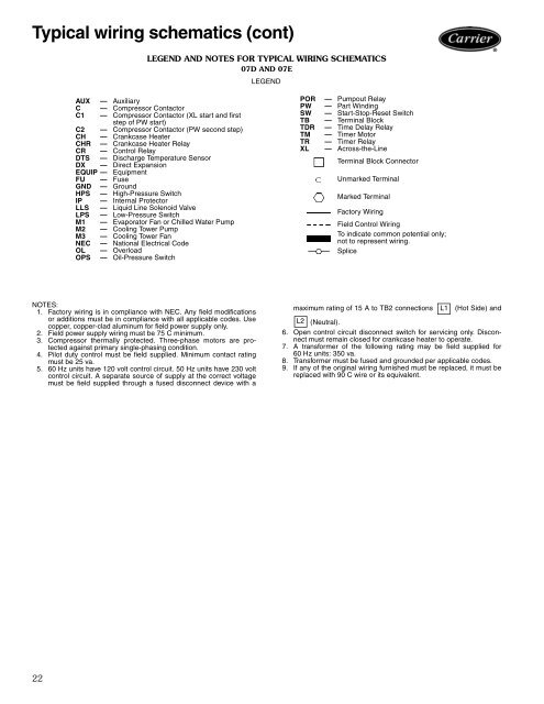
Typical wiring schematics (cont)<br />
NOTES:<br />
1. Factory wiring is in compliance with NEC. Any field modifications<br />
or additions must be in compliance with all applicable codes. Use<br />
copper, copper-clad aluminum for field power supply only.<br />
2. Field power supply wiring must be 75 C minimum.<br />
3. Compressor thermally protected. Three-phase motors are protected<br />
against primary single-phasing condition.<br />
4. Pilot duty control must be field supplied. Minimum contact rating<br />
must be 25 va.<br />
5. 60 Hz units have 120 volt control circuit. 50 Hz units have 230 volt<br />
control circuit. A separate source of supply at the correct voltage<br />
must be field supplied through a fused disconnect device with a<br />
22<br />
LEGEND AND NOTES FOR TYPICAL WIRING SCHEMATICS<br />
07D AND 07E<br />
AUX — Auxiliary<br />
C — Compressor Contactor<br />
C1 — Compressor Contactor (XL start and first<br />
step of PW start)<br />
C2 — Compressor Contactor (PW second step)<br />
CH — Crankcase Heater<br />
CHR — Crankcase Heater Relay<br />
CR — Control Relay<br />
DTS — Discharge Temperature Sensor<br />
DX — Direct Expansion<br />
EQUIP — Equipment<br />
FU — Fuse<br />
GND — Ground<br />
HPS — High-Pressure Switch<br />
IP — Internal Protector<br />
LLS — Liquid Line Solenoid Valve<br />
LPS — Low-Pressure Switch<br />
M1 — Evaporator Fan or Chilled Water Pump<br />
M2 — Cooling Tower Pump<br />
M3 — Cooling Tower Fan<br />
NEC — National Electrical Code<br />
OL — Overload<br />
OPS — Oil-Pressure Switch<br />
LEGEND<br />
POR<br />
PW<br />
—<br />
—<br />
Pumpout Relay<br />
Part Winding<br />
SW — Start-Stop-Reset Switch<br />
TB<br />
TDR<br />
—<br />
—<br />
Terminal Block<br />
Time Delay Relay<br />
TM — Timer Motor<br />
TR<br />
XL<br />
—<br />
—<br />
Timer Relay<br />
Across-the-Line<br />
Terminal Block Connector<br />
Unmarked Terminal<br />
Marked Terminal<br />
Factory Wiring<br />
Field Control Wiring<br />
To indicate common potential only;<br />
not to represent wiring.<br />
Splice<br />
maximum rating of 15 A to TB2 connections L1 (Hot Side) and<br />
L2 (Neutral).<br />
6. Open control circuit disconnect switch for servicing only. Disconnect<br />
must remain closed for crankcase heater to operate.<br />
7. A transformer of the following rating may be field supplied for<br />
60 Hz units: 350 va.<br />
8. Transformer must be fused and grounded per applicable codes.<br />
9. If any of the original wiring furnished must be replaced, it must be<br />
replaced with 90 C wire or its equivalent.