Fan Coil Units - Climayoreo
Fan Coil Units - Climayoreo
Fan Coil Units - Climayoreo

You also want an ePaper? Increase the reach of your titles
YUMPU automatically turns print PDFs into web optimized ePapers that Google loves.
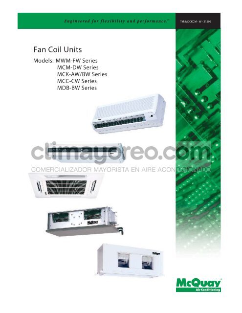
<strong>Fan</strong> <strong>Coil</strong> <strong>Units</strong><br />
Models: MWM-FW Series<br />
MCM-DW Series<br />
MCK-AW/BW Series<br />
MCC-CW Series<br />
MDB-BW Series<br />
TM: MCCKCM - W - 2150B
Contents<br />
Features ..................................................................................................................... 1<br />
Specifications ............................................................................................................. 3<br />
Unit Selection Procedure ......................................................................................... 11<br />
Cooling Capacity Performance Chart ....................................................................... 14<br />
Heating Capacity Performance Chart ....................................................................... 49<br />
Water Flow Rate Vs Pressure Drop ......................................................................... 66<br />
Correction Factors ................................................................................................... 71<br />
Wiring Diagrams ...................................................................................................... 72<br />
Controllers ............................................................................................................... 85<br />
Blower Performance Curves ..................................................................................... 91<br />
Outlines And Dimensions........................................................................................ 103<br />
General Installation Guide ..................................................................................... 112<br />
General Operation Guide ....................................................................................... 113<br />
Note: Installation and maintenance are to be performed only by qualified personnel who are<br />
familiar with local codes and regulations, and experienced with this type of equipment.<br />
Caution: Sharp edges and coil surfaces are a potential injury hazard. Avoid contact with them.<br />
Warning: Moving machinery and electrical power hazards. May cause severe personal injury or<br />
death. Disconnect and lock off power before servicing equipment.<br />
"McQuay" is a registered trademark of McQuay International. All rights reserved throughout the world.<br />
©2002 McQuay International<br />
"Bulletin illustrations cover the general appearance of McQuay International products at the time of publication<br />
and we reserve the right to make changes in design and construction at any time without notice."
Features<br />
Space Saving<br />
Different types of fan coil units are designed to be both versatile and space saving to suit every interior<br />
design. Ceiling concealed type for the sophisticated, luxurious floor space saving, all kind of interior<br />
decoration; ceiling exposed type for economical and space saving installation; etc.<br />
Zone Control<br />
These fan coil units can be installed in different zones as each unit operates independently. Zone control on<br />
energy saving, different comfort requirement; better air distribution needs can therefore be easily achieved.<br />
Unique Features For MWM-FW Series<br />
Easy Installation<br />
The wall mounted fan coil unit is easily installed because of its compact size, slimness and light weight. Slim<br />
and short outdoor unit can be easily installed even in a narrow balcony and passageway and yet have a<br />
stable profile.<br />
Space Saving<br />
No space is required on either floor or ceiling. This newly developed super slim design for wall mounting<br />
maximises floor space usage and enhance ceiling appearance where ceilings are low.<br />
Quiet Operation<br />
Cooling comfort is improved by whisper-quiet operation which is achieved by a tangential fan.<br />
Excellent Air Distribution<br />
Air discharge direction can be adjusted in four directions, manually or automatically by using LCD remote<br />
control, coupled with good air flow, the unit provides excellent air distribution.<br />
Facilitated Maintenance Ensured<br />
The new design cassette filter is slide-out type which can be easily removed at the air inlet grille for cleaning.<br />
Maintenance is easy for electrical components, piping and wiring as these are all easily accessible by merely<br />
removing front plastic panel.<br />
Wireless Remote Control<br />
The compact LCD transmitter is able to operate the air conditioner unit within the distance of 9 meters. <strong>Fan</strong><br />
motor speed can be set at low/medium/high or automatic.Sleep mode automatically increase set temperature<br />
since room temperature is lower at night thus achieving comfort surrounding. Air flow direction can be<br />
controlled automatically. Room temperature is controlled by electronic thermostat. The unit can be preset to<br />
on and off automatically for maximum of 15 hours by using timer on/off.<br />
Slit Fin<br />
The unique Hydrophilic slit fin has greatly improved the air flow and the contact surfaces with the air thus to<br />
boost the cooling capacity.<br />
1
Unique Features For MCK-AW/BW Series<br />
Built In High Head Drain Pump<br />
The unit comes with a built in high head drain pump. Condensate water can be pumped up to 500mm and<br />
drain out smoothly.<br />
4-Way Air Discharge And Air Swing<br />
These features greatly improve the air distribution in the conditioned space.<br />
Wireless And Wired Controller Option<br />
Wireless Handset is the standard controller. However if wired controller required, Netware wired controller<br />
is a wise choice(optional).<br />
Unique Features For MCM-DW Series<br />
2-Way Air Discharge And Air Swing<br />
The 2-way air discharge couple with the air swing function, provide better air distribution in the conditioned<br />
space.<br />
Easy Maintenance<br />
The air filter and components can be easily accessed from the bottom of the unit. This make servicing and<br />
maintenance become a simple task.<br />
Wireless And Wired Controller Option<br />
Wireless Handset is the standard controller. However if wired controller required, Netware wired controller<br />
is a wise choice(optional).<br />
Unique Features For MCC-CW Series<br />
Elegance And Prestige<br />
As the unit is installed above the ceiling with only the supply and return air grille exposed to view, the air<br />
conditioned space will appear as elegant and prestigious as a centralized air conditioned area.<br />
Evergreen Design<br />
This unit will never become obsolete as the unit is completely concealed away. Interior decoration for<br />
maximum aesthetic beauty as well as interior design is easily achieved.<br />
Superior Air Distribution<br />
As the conditioned air can be distributed to every corner of the area by air duct, this will ensure more<br />
pleasant living environment, thus provide extra comfort to the occupants.<br />
Optional Duct Accessories<br />
The optional duct accessories makes the ducting and installation work so easy.<br />
Optional Wired Controller<br />
Optional Netware wired controller offers simple and flexibility in controlling the unit.<br />
Unique Features For MDB-BW Series<br />
Superb Air Distribution<br />
These units are designed with high air flow and static, enables adequate distribution of air to the desired<br />
space. Providing comfort to every corner of the room.<br />
Reliability<br />
The structures are strong and robust to ensure the product operation life.<br />
Versatile<br />
Multiple rooms can be cooled together by just using one unit of MDB.<br />
2
Specifications<br />
MODEL<br />
PERFORMANCE<br />
005FW 007FW 010FW 015FW 020FW 025FW<br />
High 300 / 510 300 / 510 270 / 127 300 / 142 480 / 227 580 / 274<br />
Air Flow (CFM / L/s) Medium 230 / 390 230 / 390 230 / 109 270 / 127 430 / 203 485 / 229<br />
Low 190 / 320 190 / 320 190 / 90 230 / 109 370 / 175 380 / 179<br />
kcal/hr 1210 1638 2520 3024 4284 5292<br />
Nominal Total Cooling Capacity W 1410 1910 2931 3517 4982 6154<br />
Btu/hr 4800 6500 10000 12000 17000 21000<br />
kcal/hr 1179 1373 1739 2026 2956 3651<br />
Sensible Cooling Capacity W 1375 1600 2022 2356 3438 4247<br />
Btu/hr 4680 5447 6900 8040 11730 14490<br />
Nominal Total Heating Capacity kcal/hr 2772 3150 4032 4536 6552 8064<br />
(Entering water Temp. : 60°C) W 3220 3660 4689 5275 7620 9378<br />
Btu/hr 11000 12500 16000 18000 26000 32000<br />
Water Flow Rate USGPM / LITRES/M 1.10 / 4.16 1.54 / 5.83 2.00 / 7.57 2.67 / 10.11 4.22 / 15.97 5.33 / 20.18<br />
Head Loss (Cooling) psi / Pa 0.245 / 1689 0.436 / 3006 7.77 / 53572 12.93 / 89149 4.89 / 33715 7.40 / 51021<br />
Head Loss (Heating) : 60 °C<br />
COIL<br />
psi / Pa 0.186 / 1282 0.335 / 2310 6.09 / 41989 10.28 / 70878 3.86 / 26614 5.86 / 40403<br />
Type<br />
Tube<br />
Fin<br />
Connection<br />
Number of rows / fin per inch 1 / 18 1 / 20 2 / 18 2 / 18 2 / 18 2 / 18<br />
Max. Working Pressure (kg/cm 2 ) / (psi)<br />
Testing Pressure<br />
Surface Area m 2 / ft 2<br />
MWM<br />
Seamless copper tube mechanically boded to aluminium slit fin.<br />
OD 7mm, thickness 0.35 mm.<br />
thickness 0.11 mm<br />
OD 1/2" copper tube<br />
16.4 / 233<br />
30 kg/cm<br />
0.208 / 2.239 0.208 / 2.239 0.198 / 2.131 0.198 / 2.131 0.254 / 2.733 0.254 / 2.733<br />
Surface Air Velocity<br />
MOTOR<br />
(m/s) / (ft/min) 0.690 / 135.84 0.690 / 135.84 0.64 / 126.70 0.72 / 140.78 0.89 / 175.63 1.08 / 212.22<br />
Type<br />
Power Supply V/Ph/Hz<br />
Rated Input power W (50/60Hz) 25 25 25 / 26 25 / 26 53 / 67 57 / 81<br />
Rated Running Current A (50/60Hz) 0.11 0.11 0.11 / 0.12 0.11 / 0.12 0.23 / 0.31 0.24 / 0.38<br />
Poles<br />
High <strong>Fan</strong> 38 38 45 47<br />
Sound Level (dBA) Medium <strong>Fan</strong> 34 35 42 44<br />
Low <strong>Fan</strong> 30 31 39 42<br />
Room Temp.<br />
Control Air Discharge<br />
Operation<br />
Condensate Drain Size mm<br />
AIR FILTER<br />
WEIGHT kg 12 12 12 12 15 15<br />
DIMENSION (H x W x D) mm<br />
2 for 1 min, leak test : 16 kg/cm 2 for 5 min.<br />
Permanent split capacitor motor<br />
220 - 240 / 1 / 50 , 208 - 230 / 1 / 60<br />
4<br />
Micro-computer Controlled Thermostat<br />
Automatic Louver (Up & Down)<br />
LCD wireless micro-computer remote control<br />
19.05<br />
Washable Saran Net Filter<br />
290 x 815 x 179<br />
306 x 1062 x 202<br />
Condition<br />
Cooling capacity : Entering air temp. : 26.7 °C ( 80 °F ) DB, 19.4 °C ( 67 °F ) WB<br />
Entering water temp. : 7.2 °C ( 45 °F )<br />
Leaving water temp. : 12.8 °C ( 55 °F )<br />
Heating capacity : Entering air temp. : 21.1 °C ( 64 °F ) DB<br />
Entering water temp. : 60 °C ( 140 °F )<br />
Leaving water temp. : 55 °C ( 131 °F )<br />
Microphone position : 1m in front of the unit & 0.8m below the vertical centre line of the unit. (JIS C 9612)<br />
3
MODEL<br />
PERFORMANCE<br />
020AW 025AW 030AW 040AW 050AW<br />
High 770 / 1,310 810 / 1,380 920 / 1,560 1,020 / 1,740 1,080 / 1,840<br />
Air Flow (CFM/CMH) Medium 650 / 1,100 700 / 1,190 770 / 1,320 900 / 1,530 990 / 1,680<br />
Low 630 / 1,070 630 / 1,070 700 / 1,190 790 / 1,340 910 / 1,540<br />
kcal/hr 6,048 6,804 7,964 9,073 9,829<br />
Nominal Total Cooling Capacity W 7,034 7,913 9,261 10,551 11,430<br />
Btu/hr 24,000 27,000 31,600 36,000 39,000<br />
kcal/hr 4,209 4,738 5,494 6,162 6,628<br />
Sensible Cooling Capacity W 4,894 5,510 6,389 7,166 7,708<br />
Btu/hr 16,700 18,800 21,800 24,450 26,300<br />
Nominal Total Heating Capacity kcal/hr 9,451 10,585 12,198 13,584 14,365<br />
(Entering water Temp. : 60 °C) W 10,991 12,309 14,185 15,797 16,706<br />
Btu/hr 37,500 42,000 48,400 53,900 57,000<br />
Water Flow Rate USGPM / LITRES/M 5.32 / 20.17 6.22 / 23.45 7.11 / 26.84 8.00 / 30.14 8.88 / 33.49<br />
Head Loss (Cooling) psi / Pa 2.13 / 14,686 3.16 / 21,774 4.36 / 30,061 7.29 / 50,263 10.99 / 75,773<br />
Head Loss (Heating) : 60 °C<br />
COIL<br />
psi / Pa 1.70 / 11,721 2.545 / 17,547 3.55 / 24,476 6.07 / 41,851 9.20 / 63,459<br />
Type<br />
Tube<br />
Fin<br />
Connection<br />
Number of rows / fin per inch 2/12 2/14 2/16 2/16 2/16<br />
Max. Working Pressure (kg/cm 2 ) / (psi)<br />
Testing Pressure<br />
Surface Area m 2 / ft 2<br />
MCK<br />
Seamless copper tube mechanically bonded to aluminium slit fin<br />
OD 9.52 mm, thickness 0.35 mm<br />
Thickness 0.11 mm<br />
OD 3/4" copper tube<br />
16.4 / 233<br />
30 kg/cm<br />
0.459 / 5.022 0.459 / 5.022 0.459 / 5.022 0.459 / 5.022 0.459 / 5.022<br />
Surface Air Velocity<br />
MOTOR<br />
(m/s) / (ft/min) 0.78 / 153.33 0.82 / 161.29 0.93 / 183.19 1.03 / 203.11 1.09 / 215.05<br />
Type<br />
Power Supply V/Ph/Hz<br />
Rated Input W 127 / 139 151 / 163 164 / 208 192 / 321 253 / 328<br />
Running Current A 0.53 / 0.64 0.65 / 0.75 0.69 / 0.98 0.80 / 1.50 1.08 / 1.50<br />
Poles<br />
Room Temp.<br />
Control Air Discharge<br />
Operation<br />
Condensate Drain Size mm<br />
AIR FILTER<br />
WEIGHT (Unit + panel) kg 21 + 4 32 + 4 35 + 4 38 + 4 40 + 4<br />
DIMENSION (H x W x D) mm<br />
2 for 1 min, leak test : 16 kg/cm 2 for 5 min<br />
Permanent split capacitor motor<br />
220 - 240 / 1 / 50, 208 - 230/1/60<br />
6<br />
Micro-computer Controlled Thermostat<br />
Automatic Louver (Up & Down)<br />
LCD wireless micro-computer remote control<br />
19.05<br />
Washable Saran Net Filter<br />
335 x 820 x 820 ( 363 x 930 x 930 )<br />
Condition<br />
Cooling capacity : Entering air temp. : 26.7°C (80°F)DB, 19.4C (67°F)WB<br />
Entering water temp. : 7.2°C (45°F)<br />
Leaving water temp. : 12.8°C (55°F)<br />
Heating capacity : Entering air temp. : 21.1°C (64°F)DB<br />
Entering water temp. : 60°C (140°F)<br />
Leaving water temp. : 55°C (131°F)<br />
4
MODEL<br />
PERFORMANCE<br />
015BW 020BW 025BW 030BW<br />
High 430 / 203 430 / 203 500 / 236 607 / 287<br />
Air Flow (CFM / L/s) Medium 370 / 175 370 / 175 450 / 212 537 / 253<br />
Low 310 / 146 310 / 146 390 / 184 475 / 224<br />
kcal/hr 3150 4284 5040 5796<br />
Nominal Total Cooling Capacity W 3660 4977 5860 6740<br />
Btu/hr 12500 17000 20000 23000<br />
kcal/hr 2331 2853 3352 3872<br />
Sensible Cooling Capacity W 2708 3315 3897 4499<br />
Btu/hr 9250 11322 13300 15364<br />
Nominal Total Heating capacity kcal/hr 5292 6300 7308 8316<br />
(Entering water Temp. : 60 °C) W 6150 7320 8500 9663<br />
Btu/hr 21000 25000 29000 33000<br />
Water Flow Rate USGPM/LITRES/M 3.34 / 12.7 4.44 / 16.8 5.54 / 21 6.64 / 25<br />
Head Loss (Cooling) psi / Pa 0.582 / 4013 1.849 / 12749 2.739 / 18885 3.78 / 26063<br />
Head Loss (Heating) : 60 °C<br />
COIL<br />
psi / Pa 0.455 / 3137 1.461 / 10074 2.189 / 15093 3.055 / 21064<br />
Type<br />
Tube<br />
Fin<br />
Connection<br />
Number of rows / fin per inch 1 / 18 2 / 14 2 / 14 2 / 14<br />
Max. Working Pressure (kg/cm 2 )/(psi)<br />
Testing Pressure<br />
Surface Area m 2 /ft 2<br />
MCK<br />
Seamless copper tube mechanically bonded to aluminium slit fin.<br />
OD 9.52 mm, thickness 0.35 mm.<br />
thickness 0.11 mm<br />
OD 3/4" copper tube<br />
16.4 / 233<br />
30 kg/cm<br />
0.431 / 4.637 0.416 / 4.483 0.416 / 4.483 0.416 / 4.483<br />
Surface Air Velocity<br />
MOTOR<br />
(m/s)/(ft/min) 0.471 / 92.73 0.487 / 95.91 0.567 / 111.53 0.688 / 135.40<br />
Type<br />
Power Supply V/Ph/Hz<br />
Rated Input power W (50/60Hz) 72 / 73 72 / 73 79 / 88 108 / 108<br />
Rated Running Current A (50/60Hz) 0.31 / 0.34 0.31 / 0.34 0.33 / 0.41 0.45 / 0.50<br />
Poles<br />
Sound pressure level ( dBA ) High <strong>Fan</strong> 43.7 43.7 44 47<br />
Medium <strong>Fan</strong> 39 39 40 44<br />
Low <strong>Fan</strong> 37.5 37.5 38 40<br />
Room Temp.<br />
Control Air Discharge<br />
Operation<br />
Condensate Drain Size mm<br />
AIR FILTER<br />
WEIGHT (Unit + Panel) kg 30 + 3 30 + 3 31 + 3 32 + 3<br />
DIMENSION - HxWxD ( ) - with panel mm<br />
2 for 1 min, leak test : 16 kg/cm 2 for 5 min.<br />
Permanent split capacitor motor<br />
220 - 240 / 1 / 50 , 208 - 230 / 1 / 60<br />
6<br />
Micro-computer Controlled Thermostat<br />
Manual Louver<br />
LCD wireless micro-computer remote control<br />
19.05<br />
Washable Saran Net Filter<br />
293 x 650 x 650 (363 x 930 x 930)<br />
Condition<br />
Cooling capacity : Entering air temp. : 26.7 °C ( 80 °F ) DB, 19.4 °C ( 67 °F ) WB<br />
Entering water temp. : 7.2 °C ( 45 °F )<br />
Leaving water temp. : 12.8 °C ( 55 °F )<br />
Heating capacity : Entering air temp. : 21.1 °C ( 64 °F ) DB<br />
Entering water temp. : 60 °C (140 °F)<br />
Leaving water temp. : 55 °C (131 °F)<br />
Microphone position : MCK015-025B - 1.4m below the facia (JIS C 9612) , MCK030B - 1.5m below the facia (JIS B 8615).<br />
5
MODEL<br />
PERFORMANCE<br />
020DW 025DW 030DW 040DW 050DW<br />
High 590 / 1,000 660 / 1,130 730 / 1,240 1,000 / 1,700 1,110 / 1,890<br />
Air Flow (CFM/CMH) Medium 530 / 900 650 / 1,110 720 / 1,220 950 / 1,620 1,070 / 1,820<br />
Low 420 / 710 580 / 990 680 / 1,160 930 / 1,580 1,000 / 1,700<br />
kcal/hr 5,040 5,544 6,552 9,535 12,096<br />
Nominal Total Cooling Capacity W 5,862 6,448 7,620 11,137 14,068<br />
Btu/hr 20,000 22,000 26,000 38,000 48,000<br />
kcal/hr 3,528 3,825 4,455 6,485 7,983<br />
Sensible Cooling Capacity W 4,102 4,448 5,180 7,538 9,282<br />
Btu/hr 14,000 15,180 17,680 25,730 31,680<br />
Nominal Total Heating Capacity kcal/hr 7,560 8,442 9,674 16,207 17,065<br />
(Entering water Temp. : 60 °C) W 8,792 9,818 11,250 18,639 19,846<br />
Btu/hr 30,000 33,500 38,385 63,600 67,715<br />
Water Flow Rate USGPM / LITRES/M 4.44 / 16.75 4.88 / 18.42 5.76 / 21.77 8.44 / 31.82 10.66 / 40.19<br />
Head Loss (Cooling) psi / Pa 2.95 / 20,315 3.52 / 24,250 3.17 / 21,875 5.96 / 41,170 9.19 / 63,330<br />
Head Loss (Heating) : 60 °C<br />
COIL<br />
psi / Pa 2.46 / 16,915 2.83 / 20,191 2.64 / 18,215 4.98 / 34,279 7.65 / 52,731<br />
Type<br />
Tube<br />
Fin<br />
Connection<br />
Number of rows / fin per inch 3/12 3/12 3/12 4/12 4/14<br />
Max. Working Pressure (kg/cm 2 ) / (psi)<br />
Testing Pressure<br />
Surface Area m 2 / ft 2<br />
MCM<br />
Seamless copper tube mechanically bonded to aluminium slit fin<br />
OD 9.52 mm, thickness 0.35 mm<br />
Thickness 0.11 mm<br />
OD 3/4" copper tube<br />
16.4 / 233<br />
30 kg/cm<br />
0.217 / 2.338 0.217 / 2.338 0.263 / 2.826 0.406 / 4.361 0.406 / 4.361<br />
Surface Air Velocity<br />
MOTOR<br />
(m/s) / (ft/min) 1.28 / 252.35 1.43 / 282.29 1.31 / 258.32 1.16 / 229.31 1.29 / 254.53<br />
Type<br />
Power Supply V/Ph/Hz<br />
Rated Input W 96 / 114 130 / 155 132 / 179 240 / 337 240 / 337<br />
Running Current A 0.40 / 0.50 0.58 / 0.70 0.58 / 0.80 1.04 / 1.50 1.04 / 1.50<br />
Poles<br />
Sound pressure level ( H / M / L ) dBA 50 / 47 / 40 54 / 53 / 50 51 / 50 / 48 54 / 53 / 52 54 / 53 / 52<br />
Room Temp.<br />
Control Air Discharge<br />
Operation<br />
Condensate Drain Size mm<br />
AIR FILTER<br />
WEIGHT kg 43 43 45 70 70<br />
DIMENSION (H x W x D) mm 249 x 1,214 x 670<br />
2 for 1 min, leak test : 16 kg/cm 2 for 5 min<br />
Permanent split capacitor motor<br />
220 - 240 / 1 / 50, 208 - 230/ 1 / 60<br />
4<br />
Micro-computer Controlled Thermostat<br />
Automatic Louver (Up & Down)<br />
LCD wireless micro-computer remote control<br />
19.05<br />
Washable Saran Net Filter<br />
214 X 1,214 X 670<br />
249 X 1,714 X 670<br />
Condition<br />
Cooling capacity : Entering air temp. : 26.7°C (80°F)DB, 19.4C (67°F)WB<br />
Entering water temp. : 7.2°C (45°F)<br />
Leaving water temp. : 12.8°C (55°F)<br />
Heating capacity : Entering air temp. : 21.1°C (64°F)DB<br />
Entering water temp. : 60°C (140°F)<br />
Leaving water temp. : 55°C (131°F)<br />
6
MODEL<br />
PERFORMANCE<br />
010CW 015CW 020CW 025CW<br />
High 300 / 510 430 / 730 620 / 1,050 840 / 1,430<br />
Air Flow (CFM/CMH) Medium 280 / 480 310 / 530 610 / 1,040 790 / 1,340<br />
Low 240 / 410 270 / 460 500 / 850 640 / 1,090<br />
kcal/hr 2,520 3,780 4,788 6,048<br />
Nominal Total Cooling Capacity W 2,931 4,397 5,569 7,034<br />
Btu/hr 10,000 15,000 19,000 24,000<br />
kcal/hr 1,789 2,646 3,352 4,234<br />
Sensible Cooling Capacity W 2,081 3,078 3,898 4,924<br />
Btu/hr 7,100 10,500 13,300 16,800<br />
Nominal Total Heating Capacity kcal/hr 4,032 6,048 7,560 9,324<br />
(Entering water Temp. : 60 °C) W 4,690 7,034 8,793 10,845<br />
Btu/hr 16,000 24,000 30,000 37,000<br />
Water Flow Rate USGPM / LITRES/M 2.22 / 8.40 3.33 / 12.61 4.44 / 16.81 5.55 / 21.01<br />
Head Loss (Cooling) psi / Pa 1.53 / 10550 3.48 / 24000 2.92 / 20130 4.70 / 32410<br />
Head Loss (Heating) : 60 °C<br />
COIL<br />
psi / Pa 1.21 / 8340 2.8 / 19300 2.34 / 16130 3.83 / 26410<br />
Type<br />
Tube<br />
Fin<br />
Connection<br />
Number of rows / fin per inch 3/12 3/14 3/12 3/12<br />
Max. Working Pressure (kg/cm 2 ) / (psi)<br />
Testing Pressure<br />
Surface Area m 2 / ft 2<br />
OD 3/4" copper tube<br />
16.4 / 233<br />
30 kg/cm<br />
0.129 / 1.39 0.161 / 1.734 0.197 / 2.128 0.228 / 2.461<br />
Surface Air Velocity<br />
MOTOR<br />
(m/s) / (ft/min) 1.10 / 215.8 1.26 / 248.0 1.48 / 291.4 1.73 / 341.3<br />
Type<br />
Power Supply V/Ph/Hz<br />
Rated Input W 71 / 72 102 / 114 148 / 172 180 / 223<br />
Running Current A 0.30 / 0.33 0.43 / 0.53 0.65 / 0.80 0.74 / 1.01<br />
Poles<br />
Control<br />
Room Temp.<br />
Operation<br />
Condensate Drain Size mm<br />
AIR FILTER<br />
WEIGHT kg 17 21 22 25<br />
DIMENSION (H x W x D) mm 261 x 765 x 411 261 x 905 x 411 261 x 1,065 x 411 261 x 1,200 x 411<br />
2 for 1 min, leak test : 16 kg/cm 2 MCC<br />
Seamless copper tube mechanically bonded to aluminium slit fin<br />
OD 9.52 mm, thickness 0.35 mm<br />
Thickness 0.11 mm<br />
for 5 min<br />
Permanent split capacitor motor<br />
220 - 240 / 1 / 50 , 208 - 230 / 1 / 60<br />
4<br />
Micro-computer Controlled Thermostat<br />
LCD wireless micro-computer remote control<br />
19.05<br />
Washable Saran Net Filter<br />
Condition<br />
Cooling capacity : Entering air temp. : 26.7°C (80°F)DB, 19.4C (67°F)WB<br />
Entering water temp. : 7.2°C (45°F)<br />
Leaving water temp. : 12.8°C (55°F)<br />
Heating capacity : Entering air temp. : 21.1°C (64°F)DB<br />
Entering water temp. : 60°C (140°F)<br />
Leaving water temp. : 55°C (131°F)<br />
7
MODEL<br />
PERFORMANCE<br />
028CW 038CW<br />
High 1440/2450 1540/2620<br />
Air Flow (CFM/CMH) Medium 1270/2160 1450/2460<br />
Low 1120/1900 1260/2140<br />
kcal/hr 6,804 10,550<br />
Nominal Total Cooling Capacity W 7,914 12,270<br />
Btu/hr 27,000 41,864<br />
kcal/hr 4,695 7,490<br />
Sensible Cooling Capacity W 5,460 8,712<br />
Btu/hr 18,630 29,723<br />
Nominal Total Heating Capacity kcal/hr 7,056 16,872<br />
(Entering water Temp. : 60°C) W 8,207 19,623<br />
Btu/hr 28,000 66,951<br />
Water Flow Rate USGPM / LITRES/M 6.16/23.31 8.36/31.64<br />
Head Loss (Cooling) psi / Pa 2.437/16800 4.992/34420<br />
Head Loss (Heating) : 60 °C<br />
COIL<br />
psi / Pa 1.952/13460 4.084/28160<br />
Type<br />
Tube<br />
Fin<br />
Connection OD 3/4" copper tube<br />
Number of rows / fin per inch 3/18 3/14<br />
Max. Working Pressure (kg/cm 2 ) / (psi)<br />
Testing Pressure<br />
Surface Area m 2 / ft 2<br />
MCC<br />
16.4 / 233<br />
30 kg/cm<br />
0.264/2.844 0.363/3.909<br />
Surface Air Velocity<br />
MOTOR<br />
(m/s) / (ft/min) 1.14/224.44 1.764/347.16<br />
Type<br />
Power Supply V/Ph/Hz<br />
Rated Input W 300 563<br />
Running Current A 1.30 2.4<br />
Poles<br />
Room Temp.<br />
Control Air Discharge<br />
Operation<br />
Condensate Drain Size mm<br />
AIR FILTER<br />
WEIGHT kg 38 41<br />
DIMENSION (H x W x D) mm 290X942X600 310X1247X638<br />
2 for 1 min, leak test : 16 kg/cm 2 Seamless copper tube mechanically boded to aluminium slit fin.<br />
OD 9.52 mm, thickness 0.35 mm.<br />
thickness 0.11 mm<br />
for 5 min.<br />
Permanent split capacitor motor<br />
220 - 240 / 1 / 50<br />
4<br />
Micro-computer Controlled Thermostat<br />
Automatic Louver (Up & Down)<br />
LCD wireless micro-computer remote control<br />
19.05<br />
Washable Saran Net Filter<br />
Condition<br />
Cooling capacity : Entering air temp. : 26.7 °C ( 80 °F ) DB, 19.4 °C ( 67 °F ) WB<br />
Entering water temp. : 7.2 °C ( 45 °F )<br />
Leaving water temp. : 12.8 °C ( 55 °F )<br />
Heating capacity : Entering air temp. : 21.1 °C ( 64 °F ) DB<br />
Entering water temp. : 60 °C ( 140 °F )<br />
Leaving water temp. : 55 °C ( 131 °F )<br />
8
MODEL<br />
PERFORMANCE<br />
030CW 040CW 050CW 060CW<br />
High 1,030 / 1,750 1,150 / 1,960 1,540 / 2,620 1,990 / 3,380<br />
Air Flow (CFM/CMH) Medium 820 / 1,390 1,025 / 1,740 1,430 / 2,430 1,830 / 3,110<br />
Low 660 / 1,120 840 / 1,430 1,300 / 2,210 1,630 / 2,770<br />
kcal/hr 7,308 9,576 12,348 13,608<br />
Nominal Total Cooling Capacity W 8,500 11,138 14,362 15,827<br />
Btu/hr 29,000 38,000 49,000 54,000<br />
kcal/hr 5,189 6,799 8,644 9,798<br />
Sensible Cooling Capacity W 6,035 7,908 10,053 11,396<br />
Btu/hr 20,590 26,980 34,300 38,880<br />
Nominal Total Heating Capacity kcal/hr 11,592 15,120 19,152 22,680<br />
(Entering water Temp. : 60 °C) W 13,483 17,586 22,276 26,379<br />
Btu/hr 46,000 60,000 76,000 90,000<br />
Water Flow Rate USGPM / LITRES/M 6.66 / 25.21 8.88 / 33.61 11.11 / 42.06 13.33 / 50.46<br />
Head Loss (Cooling) psi / Pa 2.11 / 14550 3.78 / 26060 6.48 / 44680 1.48 / 10205<br />
Head Loss (Heating) : 60 °C<br />
COIL<br />
psi / Pa 1.68 / 11580 3.06 / 21100 5.36 / 36960 1.18 / 8140<br />
Type<br />
Tube<br />
Fin<br />
Connection<br />
Number of rows / fin per inch 3/12 3/12 3/12 3/12<br />
Max. Working Pressure (kg/cm 2 ) / (psi)<br />
Testing Pressure<br />
Surface Area m 2 / ft 2<br />
MCC<br />
Seamless copper tube mechanically bonded to aluminium slit fin<br />
OD 9.52 mm, thickness 0.35 mm<br />
Thickness 0.11 mm<br />
OD 3/4" copper tube<br />
16.4 / 233<br />
30 kg/cm<br />
0.37 / 3.98 0.31 / 3.44 0.41 / 4.40 0.48 / 5.16<br />
Surface Air Velocity<br />
MOTOR<br />
(m/s) / (ft/min) 1.31 / 258.78 1.70 / 334.30 1.78 / 350.00 1.96 / 385.66<br />
Type<br />
Power Supply V/Ph/Hz<br />
Rated Input W 421 / 486 550 / 661 670 / 767 748 / 804<br />
Running Current A 1.90 / 2.40 2.60 / 3.40 2.90 / 3.70 3.20 / 3.70<br />
Poles<br />
Control<br />
Room Temp.<br />
Operation<br />
Condensate Drain Size mm<br />
AIR FILTER<br />
WEIGHT kg 39 42 54 62<br />
DIMENSION (H x W x D) mm 378 x 929 x 474 378 x 1,045 x 474 378 x 1,299 x 474 378 x 1,499 x 474<br />
2 for 1 min, leak test : 16 kg/cm 2 for 5 min<br />
Permanent split capacitor motor<br />
220 - 240 / 1 / 50 , 208 - 230 / 1 / 60<br />
4<br />
Micro-computer Controlled Thermostat<br />
LCD wireless micro-computer remote control<br />
19.05<br />
Washable Saran Net Filter<br />
Condition<br />
Cooling capacity : Entering air temp. : 26.7°C (80°F)DB, 19.4C (67°F)WB<br />
Entering water temp. : 7.2°C (45°F)<br />
Leaving water temp. : 12.8°C (55°F)<br />
Heating capacity : Entering air temp. : 21.1°C (64°F)DB<br />
Entering water temp. : 60°C (140°F)<br />
Leaving water temp. : 55°C (131°F)<br />
9
MODEL<br />
PERFORMANCE<br />
075BW 100BW 125BW 150BW<br />
Air Flow (CFM/CMH) 2,500 / 4,250 3,200 / 5,440 4,200 / 7,140 4,600 / 7,820<br />
kcal/hr 19,152 24,696 32,760 41,076<br />
Nominal Total Cooling Capacity W 22,274 28,722 38,101 47,773<br />
Btu/hr 76,000 98,000 130,000 163,000<br />
kcal/hr 13,598 18,028 23,587 29,164<br />
Sensible Cooling Capacity W 15,810 20,961 27,425 33,909<br />
Btu/hr 53,960 71,540 93,600 115,730<br />
Nominal Total Heating Capacity kcal/hr 30,996 40,320 53,734 66,348<br />
(Entering water Temp. : 60 °C) W 36,049 46,700 62,490 77,160<br />
Btu/hr 123,000 160,000 213,215 263,270<br />
Water Flow Rate USGPM / LITRES/M 16.88 / 63.64 21.77 / 82.06 28.88 / 108.86 36.22 / 136.49<br />
Head Loss (Cooling) psi / Pa 8.72 / 60,050 2.65 / 18,230 3.55 / 24,472 2.77 / 19,092<br />
Head Loss (Heating) : 60 °C psi / Pa 7.26 / 50,000 2.20 / 15,179 2.96 / 20,377 2.31 / 15,897<br />
Ext. static<br />
COIL<br />
mmAq 10 10 15 15<br />
Type<br />
Tube<br />
Fin<br />
Connection<br />
Number of rows / fin per inch 3/14 4/12 3/14 4/14<br />
Max. Working Pressure (kg/cm 2 ) / (psi)<br />
Testing Pressure<br />
Surface Area m 2 / ft 2 MDB<br />
Seamless copper tube mechanically bonded to aluminium slit fin<br />
OD 9.52 mm, thickness 0.35 mm<br />
Thickness 0.11 mm<br />
OD 1<br />
0.54 / 5.82 0.54 / 5.82 1.01 / 10.83 1.01 / 10.83<br />
Surface Air Velocity<br />
MOTOR<br />
(m/s) / (ft/min) 2.15 / 430 2.75 / 550 1.94 / 388 2.12 / 425<br />
Type<br />
Power Supply V/Ph/Hz<br />
Rated Input W 810 / 1062 1008 / 1310 2730 / 1620 3370 / 1999<br />
Running Current A 3.70 / 5.16 4.22 / 7.04 3.39 / 5.70 3.39 / 5.70<br />
Poles<br />
Number of motors 2 2 1 1<br />
Sound pressure level dBA 62 64 63 67<br />
Control<br />
Condensate Drain Size<br />
FAN<br />
mm<br />
Type/Drive<br />
Number of <strong>Fan</strong>s<br />
AIR FILTER (OPTIONAL)<br />
2 2 1 1<br />
Type<br />
Length x Height mm<br />
Quantity 2 2 1 1<br />
WEIGHT kg 96 100 140 145<br />
DIMENSION (H x W x D) mm<br />
1 / 8" copper tube<br />
16.4 / 233<br />
30 kg/cm 2 for 1 min, leak test : 16 kg/cm 2 for 5 min<br />
Permanent split capacitor motor<br />
220 - 240 / 1 / 50 , 208 - 230 / 1 / 60 415 / 3 / 50 , 415 / 3 / 60<br />
4<br />
LCD wireless micro-computer remote control<br />
25.4<br />
Centrifugal fan (forward curved) / Direct Centrifugal fan (forward curved) / Belt Driven<br />
Washable Saran Net Filter<br />
622 x 433<br />
572 x 1,502 x 761<br />
885 x 1,640 x 1,040<br />
Condition<br />
Cooling capacity : Entering air temp. : 26.7°C (80°F)DB, 19.4C (67°F)WB<br />
Entering water temp. : 7.2°C (45°F)<br />
Leaving water temp. : 12.8°C (55°F)<br />
Heating capacity : Entering air temp. : 21.1°C (64°F)DB<br />
Entering water temp. : 60°C (140°F)<br />
Leaving water temp. : 55°C (131°F)<br />
10
Unit Selection Procedure<br />
The cooling and heating capacities of the fan coil units can be determined by the Cooling Capacity<br />
Performance Chart and Heating Capacity Performance Chart in the following pages based on nominal air<br />
flow at standard water temperature. The total and sensible capacities must be adjusted as variables come<br />
in. A sample of selection procedure is given as below:<br />
Step 1<br />
Determine type of fan coil units to be used, i.e. ceiling cassette (MCK-AW Series); ceiling exposed<br />
(MCM-DW Series); etc.<br />
Step 2<br />
Select a tentative unit size based on cooling capacities at nominal air flow. Design entering air<br />
temperatures and required water flows from cooling capacities chart (Page 14 - 35) or the nominal capacities<br />
ratings (Page 3 - 10) from standard specification.<br />
Step 3<br />
Determine the nominal unit cooling capacities for the unit selected. If the cooling capacities chart must be<br />
used, the following information must be known :-<br />
a) Design water temperature rise<br />
b) Design entering water temperature<br />
c) Design entering air dry bulb temperature<br />
d) Design entering air wet bulb temperature<br />
Example of how to read the cooling performance chart.<br />
Total Cooling Capacity<br />
Sensible Capacity<br />
MCK050AW<br />
11
Step 4<br />
If air flow value is different from the nominal value(high speed), then refer to specification from Page 3 to 10<br />
for the air flow required(medium or low speed). Determine the total and sensible correction factor from Air<br />
Flow Capacity Correction Factor (Page 57).<br />
Step 5<br />
If the unit is to operate at an altitude above sea level, multiply the capacity correction factors by an Altitude<br />
Correction Factors. Refer to Page 57.<br />
Step 6<br />
Calculate the actual cooling capacity by multiply the nominal capacity (from Step 3) with Air Flow Capacity<br />
Correction Factor from Step 4 and the Altitude Correction Factor from Step 5.<br />
Actual Capacity, W = Nominal capacity (Step 3) x Air Flow Capacity Correction Factor (Step 4)<br />
x Altitude Correction Factor (Step 5)<br />
Step 7<br />
Water flow rate can be determined by:<br />
Litres/Min = Total Cooling Capacity, W<br />
70 x Water Temperature Rise °C<br />
USGPM = Total Cooling Capacity, Btu/H<br />
500 x Water Temperature Rise °F<br />
Step 8<br />
Heating Capacities at nominal air flow (Page 36 to 51 - Heating Performance Chart) are based on standard<br />
condition of 60°C EWT and 21°C EAT. The actual heating capacity can be obtained by using the Heating<br />
Capacity Correction Factor (Page 57) and Altitude Correction Factor as per Step 5.<br />
Hence Actual Heating Capacity, W = Nominal Capacity (Page 36 to 51) x<br />
Heating Capacity Correction Factor (Page 57) x<br />
Air Flow Capacity Correction Factor (Step 4) x<br />
Altitude Correction Factor (Step 5)<br />
Step 9<br />
Water Pressure Drop Tables are on Page 52 to 56.<br />
EXAMPLE<br />
Select a ceiling cassette type fan coil unit at the following design specification:<br />
Room design condition : 26.7°C DB / 19°C WB<br />
Room Cooling Load : 7 kW sensible capacity / 10 kW total capacity<br />
Room Heating Load : 10 kW<br />
Entering water temperature : 7°C cooling / 54°C heating<br />
Water temperature rise : 5°C<br />
Air Volume : 1700 cmh<br />
Altitude : 600 m<br />
SOLUTION<br />
Step 1<br />
Based on the type of fan coil required and the design conditions, tentatively select MCK050AW. From the<br />
cooling capacity performance chart (Page 15), at 26.7°C DB / 19°C WB air temperature, 7°C entering water<br />
temperature and with 5°C water temperature rise, the cooling capacity for this unit is 11 kW total capacity<br />
and 7.6 kW sensible<br />
12
Step 2<br />
From page 57, the air flow correction factor table, at high speed, the air volume is 1840 cmh and medium<br />
speed is 1680 cmh, hence high speed is selected. And the correction factor is hence 1.0.<br />
If lower air flow required, then use the medium and low fan speed. The correction factor can be determined<br />
by getting the ratio of air flow (i.e. medium or low speed / high speed).<br />
Step 3<br />
As the unit is operating at 600m above sea level, the Altitude correction factor is 0.98 total and 0.93<br />
sensible.<br />
Step 4<br />
Multiply the cooling capacities obtained from step 1 (as per specification and design condition) by correction<br />
factors from (2) and (3)<br />
Actual total cooling capacity = 11 x 1.0 x 0.98 kW = 10.78 kW<br />
Actual sensible cooling capacity = 7.6 x 1.0 x 0.93 kW = 7.068 kW<br />
Step 5<br />
Water flow rate = Litres/M = 10780 W = 30.8<br />
70 x 5<br />
Step 6<br />
From Heating Capacity Performance Chart (Page 40), determine the heating capacity at the nominal air<br />
MCK050AW<br />
volume by using the flow rate calculated in Step 5. The heating capacity is at 16.18 kW.<br />
Step 7<br />
From Heating Capacity Correction Factor Tables at 54.4°C water entering temperature and 26.7°C entering<br />
air temperature, the correction factor is 0.717,<br />
Actual Heating Capacity = 16.18 x 0.98 x 0.717 = 11.37 kW<br />
Step 8<br />
Water Pressure Drop can be estimated from water Pressure Drop Table (Page 52 to 56) using interpolate<br />
method:<br />
At flow rate of 30.8 Litres/Min, the nominal pressure drop is 68,322 Pa<br />
Pressure drop correction factor = 1.2947 - 0.0021 x (EWT°C x 1.8 + 32) = 1.0234<br />
Hence the actual pressure drop = nominal pressure drop x correction factor = 69,921 Pa.<br />
13
Cooling Capacity Performance Chart<br />
MWM005FW<br />
14
MWM007FW<br />
15
MWM010FW<br />
16
MWM015FW<br />
17
MWM020FW<br />
18
MWM025FW<br />
19
MCK020AW<br />
20
MCK025AW<br />
21
MCK030AW<br />
22
MCK040AW<br />
23
MCK050AW<br />
24
MCK015BW<br />
25
MCK015BWN<br />
26
MCK020BW<br />
27
MCK025BW<br />
28
MCK030BW<br />
29
MCM020DW<br />
30
MCM025DW<br />
31
MCM030DW<br />
32
MCM040DW<br />
33
MCM050DW<br />
34
MCC010CW<br />
35
MCC015CW<br />
36
MCC020CW<br />
37
MCC025CW<br />
38
MCC030CW<br />
39
MCC040CW<br />
40
MCC050CW<br />
41
MCC060CW<br />
42
MCC028CW<br />
43
MCC038CW<br />
44
MDB075BW<br />
45
MDB100BW<br />
46
MDB125BW<br />
47
MDB150BW<br />
48
Heating Capacity Performance Chart<br />
Wall Mounted Type<br />
HEATING CAPACITY - W<br />
HEATING CAPACITY- W<br />
84.00<br />
82.00<br />
80.00<br />
78.00<br />
76.00<br />
74.00<br />
MWM010FW<br />
AWM10FW<br />
72.00<br />
4.50 5.50 6.50 7.50 8.50 9.50 10.50<br />
92.00<br />
91.00<br />
90.00<br />
89.00<br />
88.00<br />
87.00<br />
86.00<br />
85.00<br />
84.00<br />
83.00<br />
WATER FLOWRATE - LITRE/MIN<br />
MWM015FW<br />
AWM15FW<br />
82.00<br />
6.00 7.00 8.00 9.00 10.00 11.00 12.00 13.00 14.00 15.00<br />
WATER FLOWRATE - LITRE/MIN<br />
49
HEATING CAPACITY - W<br />
HEATING CAPACITY- W<br />
134.00<br />
132.00<br />
130.00<br />
128.00<br />
126.00<br />
124.00<br />
122.00<br />
120.00<br />
MWM020FW<br />
AWM20FW<br />
118.00<br />
9.00 10.00 11.00 12.00 13.00 14.00 15.00 16.00 17.00 18.00 19.00 20.00 21.00 22.00 23.00<br />
166.00<br />
164.00<br />
162.00<br />
160.00<br />
158.00<br />
156.00<br />
154.00<br />
152.00<br />
150.00<br />
148.00<br />
WATER FLOWRATE - LITRE/MIN<br />
MWM025FW<br />
AWM25FW<br />
146.00<br />
11.00 13.00 15.00 17.00 19.00 21.00 23.00 25.00 27.00 29.00<br />
WATER FLOWRATE - LITRE/MIN<br />
50
Ceiling Cassette Type<br />
MCK020AW<br />
MCK025AW<br />
51
MCK030AW<br />
MCK040AW<br />
52
MCK050AW<br />
53
HEATING CAPACITY - W<br />
HEATING CAPACITY- W<br />
108.00<br />
106.00<br />
104.00<br />
102.00<br />
100.00<br />
98.00<br />
96.00<br />
94.00<br />
MCK015BW<br />
92.00<br />
7.00 8.00 9.00 10.00 11.00 12.00 13.00 14.00 15.00 16.00 17.00 18.00<br />
130.00<br />
129.00<br />
128.00<br />
127.00<br />
126.00<br />
125.00<br />
124.00<br />
123.00<br />
122.00<br />
121.00<br />
120.00<br />
119.00<br />
118.00<br />
117.00<br />
WATER FLOWRATE - LITRE/MIN<br />
MCK020BW<br />
116.00<br />
10.00 12.00 14.00 16.00 18.00 20.00 22.00 24.00<br />
WATER FLOWRATE - LITRE/MIN<br />
54
HEATING CAPACITY- W<br />
HEATING CAPACITY - W<br />
144.00<br />
142.00<br />
140.00<br />
138.00<br />
136.00<br />
134.00<br />
132.00<br />
MCK025BW<br />
130.00<br />
12.00 13.00 14.00 15.00 16.00 17.00 18.00 19.00 20.00 21.00 22.00 23.00 24.00 25.00 26.00 27.00 28.00 29.00 30.00<br />
156.00<br />
154.00<br />
152.00<br />
150.00<br />
148.00<br />
146.00<br />
WATER FLOWRATE - LITRE/MIN<br />
MCK030BW<br />
144.00<br />
15.00 20.00 25.00 30.00 35.00<br />
WATER FLOWRATE - LITRE/MIN<br />
55
Ceiling Suspended Type<br />
MCM020DW<br />
MCM025DW<br />
56
MCM030DW<br />
MCM040DW<br />
57
MCM050DW<br />
58
Ceiling Concealed Type<br />
MCC010CW<br />
MCC015CW<br />
59
MCC020CW<br />
MCC025CW<br />
60
MCC030CW<br />
MCC040CW<br />
61
HEATING CAPACITY - W<br />
HEATING CAPACITY - W<br />
13800<br />
13300<br />
12800<br />
12300<br />
MCC028CW<br />
11800<br />
10 15 20 25 30 35<br />
20500<br />
20000<br />
19500<br />
19000<br />
18500<br />
18000<br />
WATER FLOW RATE - LITRES/M<br />
MCC038CW<br />
17500<br />
15 20 25 30 35 40 45 50<br />
WATER FLOW RATE - LITRES/M<br />
62
MCC050CW<br />
MCC060CW<br />
63
Ducted Blower Split Type<br />
MDB075BW<br />
MDB100BW<br />
64
MDB125BW<br />
MDB150BW<br />
65
Water Flow Rate Vs Pressure Drop<br />
MODELS<br />
MWM010FW<br />
MWM015FW<br />
MWM020FW<br />
MWM025FW<br />
FLOW RATE WATER PRESSURE DROP<br />
LITRES / M USGPM Pa PSI<br />
4.54 1.20 3.67 0.533<br />
6.06 1.60 6.08 0.882<br />
7.57 2.00 9.01 1.308<br />
9.08 2.40 12.55 1.822<br />
10.60 2.80 16.57 2.405<br />
6.06 1.60 6.08 0.883<br />
8.06 2.13 10.15 1.473<br />
10.11 2.67 15.22 2.209<br />
12.11 3.20 21.11 3.064<br />
14.12 3.73 27.90 4.049<br />
9.58 2.53 2.29 0.333<br />
12.76 3.37 3.80 0.551<br />
15.97 4.22 5.69 0.826<br />
19.15 5.06 7.88 1.144<br />
22.33 5.90 10.40 1.510<br />
12.07 3.19 3.45 0.501<br />
16.12 4.26 5.80 0.842<br />
20.17 5.33 8.67 1.258<br />
24.19 6.39 12.04 1.747<br />
28.24 7.46 15.95 2.315<br />
Note :<br />
a. PRESSURE DROP CORRECTION FACTOR = 1.2947 – 0.0021 * ( EWT°C * 1.8 + 32 )<br />
b. PRESSURE DROP CORRECTION FACTOR = 1.2947 – 0.0021 * EWT°F<br />
66
MODELS<br />
MCK020AW<br />
MCK025AW<br />
MCK030AW<br />
MCK040AW<br />
MCK050AW<br />
FLOW RATE WATER PRESSURE DROP<br />
LITRES / M USGPM Pa PSI<br />
10.07 2.66 8,681 1.26<br />
13.44 3.55 14,614 2.12<br />
16.81 4.44 21,869 3.17<br />
20.17 5.32 30,385 4.41<br />
26.55 7.02 40,589 5.89<br />
12.60 3.33 13,043 1.89<br />
16.81 4.44 21,890 3.18<br />
23.45 6.22 40,614 5.89<br />
25.21 6.66 46,204 6.71<br />
29.41 7.77 61,479 8.92<br />
15.10 3.99 18,079 2.62<br />
20.14 5.32 30,440 4.42<br />
26.84 7.11 52,258 7.58<br />
30.14 7.97 64,794 9.40<br />
35.28 9.32 86,339 12.53<br />
20.14 5.32 30,468 4.42<br />
26.87 7.10 52,075 7.56<br />
30.14 8.00 64,821 9.41<br />
33.61 8.88 78,911 11.45<br />
40.31 10.65 110,901 16.10<br />
25.21 6.66 46,287 6.72<br />
33.49 8.88 78,925 11.46<br />
42.06 11.11 120,093 17.43<br />
50.42 13.32 169,129 24.55<br />
58.86 15.55 228,341 33.14<br />
MODELS<br />
FLOW RATE<br />
LITRES / M USGPM<br />
WATER PRESSURE DROP<br />
Pa PSI<br />
MCK015BW<br />
7.53 1.99 1.26 0.183<br />
10.07 2.66 2.09 0.304<br />
12.60 3.33 3.13 0.455<br />
15.10 3.99 4.33 0.628<br />
17.64 4.66 5.73 0.831<br />
MCK020BW<br />
10.07 2.66 4.02 0.583<br />
13.44 3.55 6.74 0.978<br />
16.81 4.44 10.07 1.461<br />
20.14 5.32 13.96 2.026<br />
23.50 6.21 18.31 2.658<br />
MCK025BW<br />
12.60 3.33 5.98 0.868<br />
16.81 4.44 10.07 1.462<br />
21.01 5.55 15.08 2.189<br />
25.21 6.66 21.04 3.053<br />
29.41 7.77 28.10 4.078<br />
MCK030BW<br />
15.10 3.99 8.32 1.208<br />
20.14 5.32 15.22 2.209<br />
25.21 6.66 21.04 3.054<br />
30.24 7.99 29.59 4.295<br />
Note :<br />
35.28 9.32 39.36 5.713<br />
a. PRESSURE DROP CORRECTION FACTOR = 1.2947 – 0.0021 * ( EWT°C * 1.8 + 32 )<br />
b. PRESSURE DROP CORRECTION FACTOR = 1.2947 – 0.0021 * EWT°F<br />
67
MODELS<br />
MCM020DW<br />
MCM025DW<br />
MCM030DW<br />
MCM040DW<br />
MCM050DW<br />
FLOW RATE WATER PRESSURE DROP<br />
LITRES / M USGPM Pa PSI<br />
10.07 2.66 6,704 0.97<br />
13.44 3.55 11,293 1.64<br />
16.75 4.44 16,915 2.46<br />
20.14 5.32 23,509 3.41<br />
23.50 6.21 31,418 4.56<br />
12.60 3.33 10,080 1.46<br />
16.81 4.44 16,929 2.46<br />
18.42 4.88 20,191 2.83<br />
25.21 6.66 35,766 5.19<br />
29.41 7.77 47,603 6.91<br />
15.10 3.99 9,329 1.35<br />
21.77 5.76 18,215 2.64<br />
25.21 6.66 23,578 3.42<br />
30.24 7.99 33,141 4.81<br />
35.28 9.32 44,075 6.40<br />
20.14 5.32 14,800 2.15<br />
26.87 7.10 24,900 3.61<br />
31.82 8.44 34,279 4.98<br />
40.31 10.65 52,681 7.65<br />
47.05 12.43 70,195 10.19<br />
25.21 6.66 22,186 3.22<br />
33.61 8.88 37,688 5.47<br />
40.19 10.66 52,731 7.65<br />
42.06 11.11 56,987 8.27<br />
50.45 13.33 79,986 11.61<br />
58.86 15.55 106,726 15.49<br />
Note :<br />
a. PRESSURE DROP CORRECTION FACTOR = 1.2947 – 0.0021 * ( EWT°C * 1.8 + 32 )<br />
b. PRESSURE DROP CORRECTION FACTOR = 1.2947 – 0.0021 * EWT°F<br />
68
MODELS<br />
MCC010CW<br />
MCC015CW<br />
MCC020CW<br />
MCC025CW<br />
MCC028CW<br />
MCC030CW<br />
MCC038CW<br />
MCC040CW<br />
MCC050CW<br />
MCC060CW<br />
FLOW RATE WATER PRESSURE DROP<br />
LITRES / M USGPM Pa PSI<br />
5.03 1.33 10,266 1.49<br />
6.70 1.77 17,204 2.50<br />
8.40 2.22 25,900 3.76<br />
10.07 2.66 35,993 5.22<br />
11.73 3.10 47,954 6.96<br />
7.53 1.99 23,702 3.44<br />
10.07 2.66 40,086 5.82<br />
12.61 3.33 60,894 8.84<br />
13.45 3.55 68,612 9.96<br />
15.10 3.99 85,119 12.35<br />
17.64 4.66 113,685 16.50<br />
10.07 2.66 14,331 2.08<br />
13.44 3.55 24,129 3.50<br />
16.75 4.44 36,500 5.30<br />
20.14 5.32 50,972 7.40<br />
23.50 6.21 67,942 9.86<br />
12.60 3.33 10,459 1.52<br />
16.81 4.44 17,556 2.55<br />
20.10 5.33 24,455 3.55<br />
25.21 6.66 37,082 5.38<br />
29.41 7.77 49,346 7.16<br />
14.01 3.7 5594 0.78<br />
18.55 4.9 9273 1.29<br />
23.47 6.2 13999 1.95<br />
28.01 7.4 19528 2.72<br />
32.55 8.6 25703 3.58<br />
15.10 3.99 4,603 0.67<br />
20.14 5.32 7,717 1.12<br />
24.28 6.44 10,852 1.58<br />
30.24 7.99 16,067 2.33<br />
35.28 9.32 21,269 3.09<br />
18.93 5.0 11568 1.61<br />
24.98 6.6 19062 2.66<br />
31.80 8.4 29289 4.08<br />
37.85 10.0 40957 5.71<br />
44.29 11.7 54784 7.64<br />
20.14 5.32 8,358 1.21<br />
26.87 7.10 14,035 2.04<br />
31.82 8.44 19,194 2.79<br />
40.31 10.65 29,565 4.29<br />
47.05 12.43 39,335 5.71<br />
25.21 6.66 14,476 2.10<br />
33.61 8.88 24,356 3.54<br />
41.03 10.89 35,408 5.14<br />
42.05 11.11 36,930 5.36<br />
50.45 13.33 51,730 7.51<br />
58.86 15.55 68,914 10.00<br />
30.24 7.99 22,296 3.24<br />
40.31 10.65 37,929 5.51<br />
49.41 13.11 55,316 8.03<br />
60.52 15.99 80,413 11.67<br />
70.63 18.66 107,394 15.59<br />
Note :<br />
a. PRESSURE DROP CORRECTION FACTOR = 1.2947 – 0.0021 * ( EWT°C * 1.8 + 32 )<br />
b. PRESSURE DROP CORRECTION FACTOR = 1.2947 – 0.0021 * EWT°F<br />
69
MODELS<br />
MDB075BW<br />
MDB100BW<br />
MDB125BW<br />
MDB150BW<br />
FLOW RATE WATER PRESSURE DROP<br />
LITRES / M USGPM Pa PSI<br />
37.81 9.99 19,499 2.83<br />
50.42 13.32 32,900 4.78<br />
63.64 16.88 50,000 7.26<br />
75.66 19.99 70,154 10.18<br />
88.27 23.32 93,601 13.59<br />
50.45 13.33 6,304 0.92<br />
67.26 17.77 10,549 1.53<br />
82.06 21.77 15,179 2.20<br />
100.91 26.67 22,206 3.22<br />
117.71 31.11 29,503 4.28<br />
63.06 16.66 7,648 1.11<br />
84.06 22.22 12,822 1.86<br />
108.86 28.88 20,377 2.96<br />
126.12 33.33 27,036 3.92<br />
17.12 38.88 35,945 5.22<br />
75.66 20.00 5,567 0.81<br />
100.91 26.67 9,357 1.36<br />
136.49 36.22 15,897 2.31<br />
151.36 40.00 19,499 2.83<br />
176.61 46.67 26,037 3.78<br />
Note :<br />
a. PRESSURE DROP CORRECTION FACTOR = 1.2947 – 0.0021 * ( EWT°C * 1.8 + 32 )<br />
b. PRESSURE DROP CORRECTION FACTOR = 1.2947 – 0.0021 * EWT°F<br />
70
Correction Factors<br />
ALTITUDE CORRECTION FACTORS<br />
Elevation, m Total Capacity Sensible Capacity<br />
0 1.00 1.00<br />
300 0.99 0.96<br />
600 0.98 0.93<br />
900 0.97 0.90<br />
1200 0.96 0.86<br />
1500 0.94 0.83<br />
1800 0.93 0.80<br />
HEATING CAPACITY CORRECTION FACTORS<br />
EAT<br />
ENTERING TEMPERATURE, °C<br />
°C 37.8 43.3 45.0 48.8 54.4 60.0 65.5 71.1 76.7 82.2 87.7<br />
4.4 0.838 0.980 1.021 1.122 1.265 1.406 1.552 1.698 1.845 1.988 2.134<br />
7.2 0.771 0.913 0.954 1.055 1.198 1.379 1.485 1.631 1.778 1.920 2.067<br />
10.0 0.700 0.843 0.885 0.986 0.130 1.272 1.417 1.563 1.710 1.853 2.000<br />
12.7 0.631 0.773 0.817 0.918 1.062 1.205 1.349 1.495 1.639 1.786 1.931<br />
15.5 0.562 0.705 0.748 0.848 0.992 1.137 1.281 1.427 1.572 1.719 1.865<br />
18.3 0.493 0.636 0.679 0.779 0.923 1.070 1.212 1.358 1.504 1.650 1.799<br />
21.1 0.424 0.567 0.610 0.711 0.855 1.000 1.146 1.290 1.438 1.583 1.730<br />
23.9 0.354 0.498 0.541 0.642 0.786 0.932 1.078 1.222 1.369 1.515 1.664<br />
26.7 0.284 0.428 0.471 0.573 0.717 0.863 1.008 1.155 1.302 1.449 1.597<br />
Notes : Adjusted capacity, W (@ Nominal air flow) = base heating capacity (@ nominal 60°C EWT, 21.1°C EAT) x Heating Capacity<br />
Correction Factor<br />
71
Wiring Diagrams<br />
Model : MWM005/007/010/015FW (G6 Controller)<br />
Model : MWM005/007/010/015FW (SLM-3)<br />
72
Model : MWM005/007/010/015FW (Netware 2)<br />
Model : MWM005/007/010/015FWN (G6 Controller)<br />
73
Model : MWM005/007/010/015FWN (SLM-3)<br />
Model : MWM005/007/010/015FWN (Netware 2)<br />
74
Model : MWM020/025FW (G6 Controller)<br />
Model : MWM020/025FW (SLM-3)<br />
75
Model : MWM020/025FW (Netware 2)<br />
Model : MWM020/025FWN (G6 Controller)<br />
76
Model : MWM020/025FWN (SLM-3)<br />
Model : MWM020/025FWN (Netware 2)<br />
77
Model : MCK020/025/030/040/050AW C/W G6 Controller Or Netware-1 CW Wired<br />
Controller<br />
Model : MCK020/025/030/040/050AWN (With W1V3 Controller Without Valve)<br />
78
Model : MCK015/020/025/030BW<br />
Model : MCK015/020/025/030BWN (W1V3 Valveless)<br />
79
Model : MCM020/025/030/040/050DW (G6 CONTROLLER)<br />
Model : MCM020/025/030/040/050DW (NETWARE 2)<br />
80
Model : MCM020/025/030/040/050DWN<br />
Model : MCC010/015/020/025CW (Netware 2 / SLM-3)<br />
81
Model : MCC010/015/020/025CWN<br />
Model : MCC028/030/038/040/050/060CW<br />
82
Model : MCC028/030/038/040/050/060CWN<br />
83
Model : MDB075/100BW - WITHOUT CONTROLLER<br />
Model : MDB125/150BW - WITHOUT CONTROLLER<br />
84
Controllers<br />
TYPE OF CONTROLLER VS TYPE OF FAN COIL<br />
MODELS STANDARD CONTROLLER OPTIONAL CONTROLLER<br />
MCK020~050AW G6 WIRELESS CONTROL NETWARE 2 CW (WIRED CONTROLLER)<br />
MCM020~050DW G6 WIRELESS CONTROL NETWARE 2 CW (WIRED CONTROLLER)<br />
MCC010~060CW<br />
NETWARE 2 CW (WIRED<br />
CONTROLLER)<br />
-<br />
MDB075~150BW WITHOUT CONTROLLER -<br />
SELF DIAGNOSIS TABLE<br />
Wireless Wired<br />
Operation / Faulty Indication<br />
Power LED Other LEDs 7 Segment Display<br />
Blinks 4 times <strong>Fan</strong> blinks E1 Blinking Room sensor contact loose / short<br />
Blinks 4 times Sleep blinks E2 Blinking Indoor coil sensor contact loose / short<br />
Blinks 1 time Cool blinks E4 Blinking Pipe water temperature fault<br />
Blinks 2 times Cool & <strong>Fan</strong> blinks E6 Blinking Pump faulty<br />
OPERATION GUIDE FOR G6<br />
7<br />
6<br />
5<br />
FAN SPEED AND<br />
VENTILATION MODE<br />
SELECTION<br />
• Press the button until the<br />
desired fan speed is<br />
achieved.<br />
OPERATION MODES<br />
• Press the “mode” button<br />
for select the type of<br />
operating mode.<br />
• Cooling only unit:<br />
Cool→Dry→<strong>Fan</strong>.<br />
• Heating cycles:<br />
Cool→Dry→Heat→<strong>Fan</strong>.<br />
TIMER SETTING<br />
• Press set button to<br />
activate the timer setting<br />
(from 1 hour to 15 hour)<br />
of the air conditioning<br />
unit. It will be in "On" or<br />
"Off" condition after the<br />
set time depending to<br />
the current condition<br />
(either from "On" to Off"<br />
or vise versa)<br />
• To cancel the timer<br />
setting, press the button<br />
continuously until the<br />
timer display goes off.<br />
4<br />
8<br />
SIGNAL TRANSMISSION<br />
INDICATION<br />
• Blink to confirm the last setting<br />
has been send to the unit.<br />
SLEEP MODE<br />
• Press the button to activate sleep mode.<br />
This mode can only be activated while in<br />
cooling or heating mode operation. If it is<br />
activated in “COOL” mode, the set<br />
temperature will be increase 0.5°C after<br />
30 minutes, 1°C after 1 hour and 2°C<br />
after 2 hours.<br />
85<br />
2<br />
1<br />
3<br />
TEMPERATURE SETTING<br />
• Set the desire room<br />
temperature.<br />
• Press button to increase<br />
or decrease the set<br />
temperature. Setting<br />
range are between 16°C<br />
to 30°C setting (60°F to<br />
80°F)(Optional setting<br />
from 20°C to 30°C).<br />
• Press or button<br />
simultaneously will toggle<br />
the temperature setting<br />
between °C and °F.<br />
ON / OFF switch<br />
• Press to start the air<br />
conditioner unit.<br />
• Press again to stop the<br />
unit.<br />
AUTOMATIC AIR SWING<br />
• Press the button to<br />
activate the automatic air<br />
swing function. The<br />
swing angle ranging from<br />
horizontal to 25° to<br />
bottom.
Netware 2<br />
Display<br />
D<br />
F<br />
H<br />
A : <strong>Fan</strong> Speed Display<br />
• Displays the fan speed setting (Auto/High/Medium/Low)<br />
B : Operation Mode Display<br />
• Displays the current mode of operation.<br />
C : Sleep Display<br />
• Display the sleep / energy saving status.<br />
D : Error Display<br />
E : Swing Display<br />
• Display the aur swing status.<br />
F : Key Lock Display<br />
• Display indicates when key lock function is activated.<br />
G : °C or °F Display<br />
• Display the temperature in °C or °F.<br />
H : Current Time Start / Stop Time Display<br />
• Display the current time as well as the start and stop time programmed.<br />
I : On / Off Status Lamp Display<br />
J : Set Temperature or Room Temperature Display<br />
• Display the set or room temperature.<br />
Other functions<br />
• Last state memory using battery back up.<br />
For 7-days programmable time option, battery back up is used to retain the last state data.<br />
<strong>Units</strong> without battery back up will depend on the EEPROM on the main board.<br />
• Error Indicator<br />
Error code will be shown for any abnormal condition detected.<br />
Refer to main board error codes for detail.<br />
A B C<br />
86<br />
E<br />
G<br />
J<br />
I
O<br />
P<br />
Q<br />
Operation<br />
K : Operating Lamp<br />
L : On / Off<br />
• Starting operation :<br />
When the unit is off, press the ON/OFF button. The operation LED lights and the unit will be turned on.<br />
• Stopping operation :<br />
When the unit is on, press the ON/OFF button. The operation LED is extinguished and controls are<br />
turned off.<br />
M : Set Temperature<br />
• Press this button to set the temperature. By pressing up or down once, temperature changes by 1°C<br />
(or 1°F).<br />
• The temperature range is16°C to 30°C (60°F to 85°F).<br />
• In FAN mode, temperature can not be set.<br />
• Pressing up and down buttons simultaneously will toggle the temperature unit between °C and °F.<br />
• When set temperature button is pressed, the set temperature will be displayed for 5 seconds. After<br />
that, room temperature will be displayed.<br />
N : Mode<br />
• Press MODE button to select operation mode from Cool, Heat, Auto, Dry and <strong>Fan</strong>. The display will<br />
show the selected mode.<br />
O : <strong>Fan</strong><br />
• Press FAN button to select Auto, High, Medium or Low fan speed.<br />
P : Swing<br />
• Press SWING button to activate the air sweep function.<br />
Q : Sleep<br />
• Press SLEEP button to activate the sleep or energy saving mode.<br />
87<br />
K<br />
N<br />
L<br />
M
S<br />
R<br />
X<br />
Z<br />
Y<br />
R : Timer Hold / Resume Display<br />
S : Current Time Display<br />
T : Operating Lamp<br />
U : Key Lock<br />
• This feature protects the controls from being tampered with by children or unauthorized persons.<br />
• To activate, press the MINUTE button three times consecutively. ‘KEY LOCK’ symbol will appear on<br />
the LCD display.<br />
• During this time, ON/OFF button and FAN button can be used.<br />
• To cancel this feature, press the MINUTE button again three times consecutively.<br />
V : Minute<br />
• When the control is in set clock or set timer mode, pressing the HOUR button will change the set<br />
hour.<br />
W : Hour<br />
• When the control is in set clock or set timer mode, pressing the HOUR button will change the set<br />
hour.<br />
X : Day<br />
• When the control is in set clock or set timer mode, pressing the DAY button will change the set day.<br />
Y : Clock<br />
• Press button once to set the clock mode.<br />
• Press button again to disable the clock mode.<br />
• When the clock mode is activated, the time and date can be set or changed by pressing the DAY,<br />
HOUR or MINUTE buttons.<br />
Z : Timer Hold / Resume<br />
• If 7-days timer is set, the word ‘TIMER ACTIVE’ is displayed.<br />
• To clear the timer setting, press and hold the HOLD button for 2 to 3 seconds until the word ‘TIMER<br />
ACTIVE’ is no longer displayed.<br />
• To resume the timer setting after the timer has been placed on hold, press and hold the HOLD<br />
button again for 2 to 3 seconds until the word ‘TIMER ACTIVE’ is displayed.<br />
88<br />
T<br />
W<br />
U<br />
V
SLM 3 WIRED CONTROLLER<br />
8<br />
9<br />
2<br />
5<br />
AUTO<br />
HIGH<br />
TEMP<br />
MED<br />
LOW<br />
1. “ON/OFF” switch<br />
• Press to start the air conditioner unit.<br />
• Press again to stop the unit.<br />
2. Temperature setting<br />
• Set the desired room temperature.<br />
• Press button to increase or decrease the<br />
set temperature. Setting range are between<br />
16 o C to 30 o C (60 o F to 80 o F).<br />
3. Operation Modes<br />
• Press the “mode” button for select the type<br />
of operating mode.<br />
- Cooling Only :<br />
COOL, DRY, FAN<br />
- Heat Pump :<br />
AUTO, COOL, DRY, HEAT, FAN<br />
(AUTO mode is represented by both<br />
COOL and HEAT LED light on)<br />
4. <strong>Fan</strong> Speed selection.<br />
• Press the button until the desired fan speed<br />
is achieved.<br />
5. Timer.<br />
• Press the set button to select the switch timer<br />
of the air conditioner unit (the setting range is<br />
between 1 to 10 hours).<br />
TIMER<br />
SENSOR<br />
COOL<br />
DRY<br />
FAN<br />
HEAT<br />
FAN<br />
SWING<br />
SLM<br />
ON/OFF<br />
MODE<br />
SLEEP<br />
89<br />
4<br />
1<br />
3<br />
6<br />
7<br />
4<br />
7<br />
5<br />
FAN ON/OFF<br />
SWING<br />
TEMP<br />
SLEEP<br />
TIMER MODE<br />
AC5300 (OPTIONAL)<br />
6. “Sleep” mode<br />
• Press button to activate the sleep function.<br />
This function can only be activated under<br />
“cool” or heating mode operation. When it is<br />
activated under “cool” mode operation, the<br />
set temperature will increase 0.5 o C after 30<br />
minutes, 1 o C after 1 hour and 2 o C after 2<br />
hours. If it is activated under “HEAT” mode<br />
operation, the set temperature will be<br />
decreased 0.5° C after 30 minutes, 1° C<br />
after 1 hour and 2° C after 2 hours.<br />
7. Air Swing<br />
• Press button to activate the automatic air<br />
swing function.<br />
8. Sensor<br />
• Infra red sensor to receive signals from<br />
wireless controller.<br />
9. LED display<br />
• To display the set temperature (in º C) and<br />
timer delay setting (in hours).<br />
10. Transmission source<br />
• To transmit signals to the air conditioner.<br />
10<br />
1<br />
2<br />
6<br />
3
Installation Of LCD Remote Controller<br />
Step-By-Step Guide<br />
i) First, open up the casing of the LCD remote controller into its top and bottom case using a screwdriver.<br />
To do this, insert the screwdriver into the lower slot and slide it in the outward direction.<br />
ii) Fix the bottom case onto the wall with the 2 wooden screws provided. Then, insert the 4 connecting<br />
wires (from the main board) through the slot on the lower center of the case as shown below.<br />
iii) Connect one end in each of the 3 wires to the terminal block behind the top case as illustrated.<br />
iv) To select cooling only model or heatpump model, some adjustment required in the dip switch setting.<br />
v) Fasten back the top and bottom case into place. Hook the two upper claws into their respective slots<br />
and snap the lower part shut.<br />
Dip switch setting for model selection<br />
Pin Function Remarks<br />
JH & JD RESERVE JH-OFF, JD-OFF<br />
COOL, DRY, FAN JH-OFF, JD-ON<br />
COOL, DRY, FAN, HEAT JH-ON, JD-OFF<br />
COOL, DRY, FAN HEAT, AUTO JH-ON, JD-ON<br />
RTC NO REAL TIME CLOCK RTC-OFF<br />
REAL TIME CLOCK RTC-ON<br />
NO DRY WITHOUT DRY FUNCTION NO DRY-ON<br />
DRY FUNCTION NO DRY-OFF<br />
90
Blower Performance Curves<br />
BLOWER PERFORMANCE CURVE<br />
MCC 010CW<br />
91
BLOWER PERFORMANCE CURVE<br />
MCC 015CW<br />
92
BLOWER PERFORMANCE CURVE<br />
MCC 020CW<br />
93
BLOWER PERFORMANCE CURVE<br />
MCC 025CW<br />
94
BLOWER PERFORMANCE CURVE<br />
MCC 028CW<br />
95
BLOWER PERFORMANCE CURVE<br />
MCC 030CW<br />
96
BLOWER PERFORMANCE CURVE<br />
MCC 038CW<br />
97
BLOWER PERFORMANCE CURVE<br />
MCC 040CW<br />
98
BLOWER PERFORMANCE CURVE<br />
MCC 050CW<br />
99
BLOWER PERFORMANCE CURVE<br />
MCC 060CW<br />
100
Model : MDB075BW<br />
(Double Blowers)<br />
Model : MDB100BW<br />
(Double Blowers)<br />
101
Model : MDB125/150BW<br />
102
Outlines And Dimensions<br />
Indoor Unit<br />
Model: MWM 010F W / 015FW<br />
Indoor Unit<br />
Model : MWM 020FW / 025FW<br />
103<br />
Note : Dimension in mm<br />
Note : Dimension in mm
Model : MCK020/025/030/040/050AW<br />
MCK015/020/025/030BW<br />
A<br />
B<br />
C<br />
D<br />
E<br />
104<br />
F<br />
H<br />
K<br />
J<br />
I<br />
G<br />
MODEL A B C D E F G H I J K<br />
MCK-AW 820 820 363 335 28 930 930 624 622 555 555<br />
MCK-BW 650 650 345 323 22 727 727 489 489 444 444
Model : MCM 020/025DW<br />
Model : MCM 030/040/050DW<br />
Model A B C D E F G H I J K L M<br />
MCM030DW 1174 75 1082 68 58 156 1214 57 670 216 319 879 517<br />
MCM040DW 1674 75 1582 68 93 156 1714 57 670 216 319 1379 517<br />
MCM050DW 1674 75 1582 68 93 156 1714 57 670 216 319 1379 517<br />
105
Model : MCC010CW<br />
Model : MCC015/020/025CW<br />
Model A B C D E F G H I J K L M N O P<br />
MCC015CW 31 881 841 802 10 905 72 261 411 349 225 261 171 118 77 54<br />
MCC020CW 31 1041 1002 962 10 1005 72 261 411 349 225 261 174 128 55 55<br />
MCC025CW 31 1176 1137 1097 10 1200 72 261 411 349 225 261 171 118 77 54<br />
106
Model : MCC 028CW<br />
Model : MCC 038CW<br />
107
Model : MCC030CW<br />
Model : MCC040CW<br />
108
Model : MCC050CW<br />
Model : MCC060CW<br />
109
Model : MDB075/100BW<br />
Model : MDB125BW<br />
110<br />
Model A B<br />
MDB075BW 72 301.8<br />
MDB100BW 94 289.1
Model : MDB150BW<br />
111
General Installation Guide<br />
Preliminary Site Survey<br />
Electrical supply and installation is to conform to LOCAL AUTHORITY's (e.g. National Electricity Board)<br />
CODES and REGULATIONS.<br />
Voltage supply fluctuation must not exceed ± 10% of rated voltage. Electricity supply lines must be<br />
independent of welding transformers which can cause supply fluctuation.<br />
Ensure that the location is convenient for wiring and piping.<br />
Mounting<br />
For ceiling mounted models, locate a position where piping and ducting work can be kept to a minimum.<br />
Ensure that overhead supports are strong enough to hold the unit's weight. Position hanger rods and check<br />
for alignment with the unit. Check that hangers are secure and that the base of fan coil unit is level in two<br />
horizontal positions.<br />
Piping<br />
Drain and water piping must be accurately connected.<br />
Please refer to "Specification Sheet" for piping sizes.<br />
Piping Support<br />
All water mains must be adequately supported to carry the necessary weight involved, provisions must be<br />
made by the installing contractor to allow for adequate free movement of all vertical and horizontal risers and<br />
run outs. Due to the fact that cold water will be circulated through the water mains, a sizeable movement of<br />
the water mains can be expected due to contraction. If for example, the piping is rigidly supported with no<br />
provision for movement, it is very possible that the tubing of fitting may be broken causing water leakage in<br />
the conditioned spaces throughout the building.<br />
<strong>Coil</strong> Venting<br />
Each standard basic unit coil is equipped with a manually operated air vent which is installed at the end of a<br />
small copper line leading into the highest point of the coil. By means of this valve, air may be vented<br />
manually, from the coil to keep it operating at full capacity. When water is first introduced into a coil, air is<br />
sometimes trapped in the coil tubing. This trapped air will reduce cooling capacity and create "Bubbling" or<br />
"Clanking" noise within the units. To release air trapped in the coil, press the air vent head to allow air to flow<br />
out of the air vent opening. Release when a steady stream of water appear.<br />
Electrical Connection<br />
As wiring regulations differ from country to country, please refer to your LOCAL ELECTRICAL CODES for<br />
field wiring regulations and ensure that they are complied with. Besides, take note of the following general<br />
precaution:<br />
1) Ensure that the rated voltage of the unit corresponds to the name plate before commencing wiring work.<br />
2) Provide a power outlet to be used exclusively for each unit and a power supply disconnect and a circuitbreaker<br />
for over-current protection should be provided in the exclusive line.<br />
3) The unit must be EARTH to prevent possible hazards due to insulation failure.<br />
4) All wiring must be firmly connected.<br />
112
General Operation Guide<br />
Start-Up<br />
The following procedure must be completed before any attempts is made to put the entire system Into<br />
operation:<br />
1) Piping connections completed.<br />
2) Electrical connections completed.<br />
3) Duct connections completed.<br />
4) Auxiliary drain pans in position where required.<br />
5) Drain line draining into drain pans.<br />
6) Filters correctly installed and free of construction debris.<br />
7) Motor-blower assembly rotates freely.<br />
8) Unit Hydrostatically tested and air vented.<br />
Starting The <strong>Fan</strong> <strong>Coil</strong> Unit<br />
1) Turn on the switch of water pump.<br />
2) Start water chiller.<br />
3) Operate the fan coil unit by turning on the fan and set the control switch to get the desired speed.<br />
4) Inspect the duct and piping condition and rectify problem (e.g. vibration, noise, etc.) if exist.<br />
Servicing And Maintenance<br />
<strong>Fan</strong> coil units are designed to operate continuosly with minor routine maintenance. Since fan coil units cool<br />
the discharging forced air, the efficiency with which the units operate is directly related to the amount of air<br />
passing through the coil.<br />
Air Filters<br />
The function of the air filters is to remove foreign matter such as dirt, soot, pollen and certain other impurities<br />
from the air passing through it. A clogged or dirty filter not only fails to do the job for which it is designed, but<br />
restricts the flow of air over the coil.<br />
The importance of cleaning the filter before it becomes clogged must be greatly stressed. The frequency<br />
with which a filter should be cleaned will depend upon the amount of dust and foreign material that enters a<br />
unit, and this depends upon location and situation.<br />
The washable viledon or saranet filter may be cleaned by tapping the filter on a solid surface to dislodge<br />
heavy particles. Wash under stream of warm water, with detergent if necessary. Dry it thoroughly before<br />
replacing.<br />
<strong>Fan</strong> Motor<br />
The fan motor is prelubricated and sealed at the factory. Therefore, no lubricating maintenance is required.<br />
<strong>Coil</strong>s<br />
Clean coil unit by brushing between fins with a nylon brush. Brushing should be followed by cleaning with a<br />
vacuum cleaner. The coil may also be cleaned by using a high pressure air hose and nozzle if a<br />
compressed air source is available. It should be pointed out that if suitable air filter is used and taken care of<br />
properly, the coils need no cleaning.<br />
Drain Pipe<br />
The drain pipe should be checked before operation of unit is begun. If it is clogged, steps should be taken to<br />
clean the debris so that condensate will flow out easily.<br />
Replacement Of Parts<br />
Replacement of parts are available through your local dealers. When ordering parts, you must supply<br />
1) Model name of the unit.<br />
2) Serial number of the unit.<br />
3) Part name and number.<br />
113
DOP :<br />
Americas - 13600 Industrial Park Boulevard, P.O. Box 1551, Minneapolis, MINI 55440 USA (612) 553-5330<br />
Asia - Jalan Pengapit 15/19, P.O. Box 7072, 40702 Shah Alam, Selangor Darul Eshan, Malaysia - Tel: 6-03-5594922 - Fax: 6-03-5506980 - Telex: MA 38521<br />
Europe - 42 Cours Jean Jaurès - 17800 Pons - France - Tél: (33) 46 92 33 33 - Télex: 790 536 F - Télecopie: (33) 46 91 38 33