Dräger Polytron 7000 Measuring Unit, Installation Instructions
Dräger Polytron 7000 Measuring Unit, Installation Instructions
Dräger Polytron 7000 Measuring Unit, Installation Instructions

Create successful ePaper yourself
Turn your PDF publications into a flip-book with our unique Google optimized e-Paper software.
<strong>Dräger</strong> <strong>Polytron</strong> <strong>7000</strong> <strong>Measuring</strong> <strong>Unit</strong>, <strong>Installation</strong> <strong>Instructions</strong><br />
Operation of the <strong>Dräger</strong> <strong>Polytron</strong> <strong>7000</strong> or <strong>Dräger</strong> Docking Station (Part No. 83 17 990) requires<br />
full understanding and strict observance of the <strong>Instructions</strong> for Use of the <strong>Dräger</strong> <strong>Polytron</strong> <strong>7000</strong><br />
(Part No. 90 23 758)!<br />
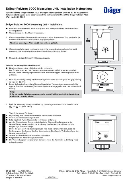
<strong>Dräger</strong> <strong>Polytron</strong> <strong>7000</strong> <strong>Measuring</strong> <strong>Unit</strong> – <strong>Installation</strong><br />
● Remove the raincover (for protection against dust and splashwater) from the installed<br />
docking station.<br />
● Check the seal for dirt. Clean if necessary.<br />
1 Check the position of the eccentric catches and adjust if necessary. The opening for the<br />
eccentric catches must face upwards, engaged position.<br />
Attention: use only an Allen key (5 mm) without golfball.<br />
● Check the polarity, cable routing and seat of the connecting terminals, and correct if<br />
necessary (see <strong>Installation</strong> <strong>Instructions</strong> of the <strong>Polytron</strong> Docking Station).<br />
● Unpack the <strong>Dräger</strong> <strong>Polytron</strong> <strong>7000</strong> measuring unit.<br />
Schalter für Back-up-Batterie einstellen<br />
● Schalterstellung prüfen – Schalter auf der Unterseite.<br />
Der Schalter muss auf " ein " stehen; ansonsten werden im Fall eines Stromausfalls<br />
Uhrzeit, Datum und die gespeicherten Daten des Datenloggers und Ereignisspeichers<br />
gelöscht.<br />
2 Push the measuring unit up into the docking station as far as it will go, i.e. roughly half-way<br />
up (approx. 60 mm).<br />
3 Lower it along the front edge of the docking station. The resistance increases slightly<br />
approx. 5 mm before the stop (the connecting terminal engages in the socket on the circuit<br />
board).<br />
Note:<br />
If the connector fails to engage correctly, check that the terminals in the docking<br />
station are correctly aligned.<br />
1 Lock the measuring unit with the Allen key by turning the eccentric catches clockwise<br />
( ⇒ = approx. 180 o ).<br />
Then fit the sensor. To do so:<br />
4 Bajonettring vom Transmitter entfernen, Blindscheibe entfernen.<br />
● Sensor aus der Verpackung nehmen.<br />
● Falls installiert, Kurzschlussbrücke vom Sensor entfernen.<br />
● Auf der Rückseite des Sensors ist ein kodierter Stecker. Den Sensor so in die<br />
Sensoröffnung einsetzen, dass die Kodierung des Steckers nach hinten und das<br />
<strong>Dräger</strong>Logo nach vorne zeigt.<br />
Bevor der Stecker in die Buchse gedrückt wird muss sichergestellt sein, dass die<br />
Kodierung von Stecker und Buchse übereinstimmt. Eine falsche Verbindung kann den<br />
Sensor beschädigen!<br />
● Sensor mit Bajonettring im Transmitter befestigen.<br />
● Gegebenenfalls Kalibrierung durchführen.<br />
● Bei Verwendung von vorkalibrierten Sensoren muss die Alarmkette (z. B. Bump Test)<br />
getestet werden.<br />
90 23 759 - MA 4683.101 en<br />
© <strong>Dräger</strong> Safety AG & Co. KGaA<br />
1 st edition - September 2003<br />
Subject to alteration<br />
ARUA-F001<br />
2<br />
D<br />
<strong>Dräger</strong> Safety AG & Co. KGaA – Revalstraße 1, D-23560 Lübeck, Germany<br />
Tel. +49 451 8 82 - 27 94 – Fax +49 451 8 82 - 49 91<br />
www.draeger-safety.de<br />
3<br />
4<br />
1<br />
on off<br />
<strong>Polytron</strong><br />
OK<br />
00123759_1.eps<br />
05423758_1_en.eps<br />
00223759_1.eps
<strong>Dräger</strong> Docking Station, <strong>Installation</strong> <strong>Instructions</strong><br />
Operation of the <strong>Dräger</strong> <strong>Polytron</strong> 3000 or <strong>Polytron</strong> <strong>7000</strong> measuring unit or of the <strong>Dräger</strong><br />
Docking Station (Part No. 83 17 990) requires full understanding and strict observance of the<br />
<strong>Instructions</strong> for Use of the <strong>Dräger</strong> <strong>Polytron</strong> 3000 or <strong>Polytron</strong> <strong>7000</strong>!<br />
Installing the Docking Station<br />
— The docking station must be installed vertically (transmitter with sensor facing down) in<br />
a place having low vibrations and stable temperature – close to a possible leak.<br />
— A clear space of at least 15 cm must be maintained above the transmitter to allow for<br />
installation of the measuring unit.<br />
— A clear space of at least 10 cm – recommended 30 cm – must be maintained below<br />
the transmitter to ensure accessibility for maintenance.<br />
● Unpack the cocking station.<br />
1 Remove the raincover (protection against dust and splash-water).<br />
If using the <strong>Polytron</strong> 3000:<br />
2 Remove the 2-pin connecting terminal. Keep it in a safe place and refit it when installation<br />
is complete.<br />
If using the <strong>Polytron</strong> <strong>7000</strong>:<br />
3 Remove the 4-pin connecting terminal. Keep it in a safe place and refit it when installation<br />
is complete.<br />
● Screw the docking station into place (drilling template: see pale grey illustration in the<br />
background). Spacing between holes: 66 ±4 mm.<br />
Attention:<br />
Spacers (e.g. mounting bracket 68 09 772) must be used to prevent any twisting of<br />
the housing when installed on uneven surfaces.<br />
If the <strong>Dräger</strong> <strong>Polytron</strong> 3000/<strong>7000</strong> measuring unit is not yet installed:<br />
● Refit the raincover (protection against dust and splash-water).<br />
Installing the electrical connections – <strong>Dräger</strong> <strong>Polytron</strong> 3000<br />
— Connect to the central unit with at least a 2-core cable, 0.5 to 2.5 mm 2 (e.g. LiY, LiYCY).<br />
— If a current between 0 and 22 mA is applied, a DC voltage of between 12 V DC and<br />
30 V DC must be present at the transmitter.<br />
Install the 4 to 20 mA current loop<br />
● Insert the 2-wire connecting cable in the cable gland, cut it to length and strip the insulation<br />
(approx. 80 mm).<br />
● Shorten the shield, if fitted, so that no short-circuits can occur.<br />
● Connect the cable:<br />
1 2-pin terminal for <strong>Dräger</strong> <strong>Polytron</strong> 3000 – check polarity. Cut excess wires short<br />
or<br />
2 Fasten in 4-pin terminal.<br />
1 Slide the connecting terminal back into the holder.<br />
● Fasten cable in guide.<br />
● Fold up these <strong>Installation</strong> <strong>Instructions</strong> and place them inside the <strong>Dräger</strong> Docking Station<br />
ready for commissioning/start-up.<br />
● Refit the raincover (protection against dust and splash-water).<br />
D<br />
If installing the transmitter in Zone 0 or Zone 1 explosion-hazard areas:<br />
— Zwischen Transmitter und Zentralgerät, Sicherheitsbarriere mit entsprechender Explosionsschutz-Zulassung (Gerätekategorie 1 bzw. 2)<br />
einbauen.<br />
— Es dürfen nur Sicherheitsbarrieren mit folgenden Kennwerten verwendet werden: U max ≤30 V, I max ≤0,3 A, P max ≤ 700 mW.<br />
— Darauf achten, dass die maximal an die Sicherheitsbarriere anschließbare Kapazität und Induktivität nicht überschritten wird (Leitung berücksichtigen).<br />
Die sicherheitstechnischen Eingangsparameter des Transmitters betragen: C i = 0 µF, L i = 50 µH<br />
● Non-isolated barriers: connect shield to the equipotential bonding or to 0 V (Ex-i).<br />
4 to 20 mA<br />
+24 V<br />
Ex-hazard area zone 0 or zone 1<br />
Non-Ex-hazard area<br />
Ex i<br />
Safety barrier<br />
PA<br />
Equipotential bond<br />
1<br />
1<br />
3<br />
2<br />
2<br />
+<br />
4 ... 20 mA<br />
0 V<br />
+<br />
–<br />
Central controller<br />
00123760_1.eps<br />
00223760_1.eps<br />
00623760_1.eps<br />
00423760_1_en.eps
● Potential-free barriers: connect to the negative Ex-i connection.<br />
If installing the transmitter in Zone 2 explosion-hazard area:<br />
— Nur Speisegeräte der Gerätekategorie 3 verwenden.<br />
— Darauf achten, dass die maximal an das Speisegerät anschließbare Kapazität und Induktivität nicht überschritten wird (Leitung berücksichtigen).<br />
Die sicherheitstechnischen Eingangsparameter des Transmitters betragen: C i = 0 µF, L i = 50 µH.<br />
Caution:<br />
Kategorie 1-Kennzeichnung an vorgesehener Stelle aus dem Typenschild-Anhänger herausschneiden. Das Gerät darf nach dem<br />
erstmaligen Betrieb gemäß dieser <strong>Installation</strong> nicht mehr in explosionsgefährdeten Bereichen der Zone 0 und Zone 1<br />
(Gerätekategorie 1 oder 2) installiert werden.<br />
If installing the transmitter in areas not exposed to explosion hazard:<br />
Caution:<br />
Ex-Schutz Kennzeichnung vom Transmitter entfernen. Der Transmitter darf nach dem erstmaligen Betrieb gemäß dieser <strong>Installation</strong><br />
nicht mehr in explosionsgefährdeten Bereichen installiert werden.<br />
– +<br />
4 to 20 mA<br />
+24 V<br />
+<br />
–<br />
Ex-hazard area zone 0 or zone 1<br />
Non-es-hazard area<br />
Installing the electrical connections – <strong>Dräger</strong> <strong>Polytron</strong> <strong>7000</strong><br />
Non-Ex-hazard area<br />
Caution:<br />
By retrofitting the relay module and/or pump module to the <strong>Polytron</strong> <strong>7000</strong>, the overall device loses its “Ex” explosion-proof approval.<br />
The operator must ensure that there is no approved explosion-proof approval displayed when pump and/or relay module are installed.<br />
Remove approval label from transmitter.<br />
The <strong>Polytron</strong> <strong>7000</strong> with installed pump module and/or relay module must not be used in explosion hazard areas.<br />
2-core connection<br />
— Connect to the central unit with at least a 2-core cable, 0.5 to 2.5 mm 2 (e.g. LiY, LiYCY).<br />
— If a current between 0 and 22 mA is applied, a DC voltage of between 16.5 V DC and<br />
30 V DC must be present at the transmitter.<br />
Safety barrier<br />
● Install the 4 to 20 mA current loop<br />
● Insert the 2-wire connecting cable in the cable gland, cut it to length and strip the insulation<br />
(approx. 80 mm).<br />
● Shorten the shield, if fitted, so that no short-circuits can occur.<br />
● Connect the cable:<br />
1 4-pin terminal for <strong>Dräger</strong> <strong>Polytron</strong> <strong>7000</strong> – observe polarity. Cut excess wires short or<br />
2 Fasten in the middle terminals.<br />
● Fasten the cable in the holder.<br />
● Fold up these <strong>Installation</strong> <strong>Instructions</strong> and place them inside the <strong>Dräger</strong> Docking Station<br />
ready for commissioning/start-up.<br />
● Refit the raincover (protection against dust and splash-water).<br />
Ex i<br />
PA<br />
Equipotential<br />
2<br />
+<br />
4 ... 20 mA<br />
0 V<br />
+<br />
–<br />
Central controller<br />
+<br />
4 ... 20 mA<br />
0 V<br />
+<br />
–<br />
Central controller<br />
+24 V<br />
0 V<br />
0 V<br />
Signal<br />
1<br />
00523760_1_en.eps<br />
00323760_1_en.eps<br />
01023760_1.eps
If installing the transmitter in Zone 0 or Zone 1 explosion-hazard areas:<br />
— Zwischen Transmitter und Zentralgerät, Sicherheitsbarriere mit entsprechender Explosionsschutz-Zulassung (Gerätekategorie 1 bzw. 2)<br />
einbauen.<br />
— Es dürfen nur Sicherheitsbarrieren mit folgenden Kennwerten verwendet werden: U max ≤30 V, I max ≤0,3 A, P max ≤700 mW.<br />
— Darauf achten, dass die maximal an die Sicherheitsbarriere anschließbare Kapazität und Induktivität nicht überschritten wird (Leitung berücksichtigen).<br />
Die sicherheitstechnischen Eingangsparameter des Transmitters betragen: C i = 5 nF, L i = 50 µH.<br />
● Non-isolated barriers: connect shield to the equipotential bonding or to 0 V (Ex-i).<br />
4 to 20 mA<br />
+24 V<br />
● Potential-free barriers: connect to the negative Ex-i connection.<br />
4 to 20 mA<br />
+24 V<br />
Ex-hazard area zone 0 or zone 1<br />
If installing the transmitter in Zone 2 explosion-hazard areas or in areas not exposed to explosion hazard:<br />
— Nur Speisegeräte der Gerätekategorie 3 verwenden.<br />
— Darauf achten, dass die maximal an das Speisegerät anschließbare Kapazität und Induktivität nicht überschritten wird (Leitung berücksichtigen).<br />
Die sicherheitstechnischen Eingangsparameter des Transmitters betragen: C i = 5 nF, Li = 50 µH.<br />
Caution:<br />
Kategorie 1-Kennzeichnung an vorgesehener Stelle aus dem Typenschild-Anhänger herausschneiden. Das Gerät darf nach dem<br />
erstmaligen Betrieb gemäß dieser <strong>Installation</strong> nicht mehr in explosionsgefährdeten Bereichen der Zone 0 und Zone 1<br />
(Gerätekategorie 1 oder 2) installiert werden.<br />
If installing the transmitter in areas not exposed to explosion hazard:<br />
Non-Ex-hazard area<br />
Safety barrier<br />
Caution:<br />
Ex-Schutz Kennzeichnung vom Transmitter entfernen. Der Transmitter darf nach dem erstmaligen Betrieb gemäß dieser <strong>Installation</strong><br />
nicht mehr in explosionsgefährdeten Bereichen installiert werden.<br />
+24 V<br />
4 to 20 mA<br />
Ex-hazard area zone 0 or zone 1<br />
Non-Ex-hazard area<br />
Connection to central unit<br />
● Connect the shield to the earth of the central unit (e.g. housing, earthing rail etc.)<br />
If installing more than one transmitter and HART multidrop-capable central unit<br />
● Observe the installation instructions in the <strong>Instructions</strong> for Use of the <strong>Dräger</strong> <strong>Polytron</strong> <strong>7000</strong>.<br />
3-core connection<br />
Install the 4 to 20 mA current loop<br />
● Insert the 3-wire connecting cable in the cable gland, cut it to length and strip the insulation<br />
(approx. 80 mm).<br />
● Shorten the shield, if fitted, so that no short-circuits can occur.<br />
● Connect the cable:<br />
1 Fasten in the terminals of the 4-pin terminal block for <strong>Dräger</strong> <strong>Polytron</strong> <strong>7000</strong><br />
Check correct polarity. Slide the terminal block back into the holder.<br />
● Fasten the cable in the holder.<br />
● Fold up these <strong>Installation</strong> <strong>Instructions</strong> and place them inside the <strong>Dräger</strong> Docking Station<br />
ready for commissioning/start-up.<br />
● Refit the raincover (protection against dust and splash-water).<br />
Ex i<br />
PA<br />
Non-Ex-hazard area<br />
Ex i<br />
Safety barrier<br />
PA<br />
Equipotential bond<br />
Equipotential bond<br />
+<br />
4 ... 20 mA<br />
0 V<br />
+<br />
–<br />
Central controller<br />
+<br />
4 ... 20 mA<br />
0 V<br />
+<br />
–<br />
Central controller<br />
+<br />
4 ... 20 mA<br />
0 V<br />
+<br />
–<br />
Central controller<br />
+24 V<br />
0 V<br />
0 V<br />
Signal<br />
1<br />
00823760_1_en.eps<br />
00923760_1_en.eps<br />
00723760_1_en.eps<br />
01423760_1.eps
If installing the transmitter in areas not exposed to explosion hazard:<br />
Caution:<br />
Ex-Schutz Kennzeichnung vom Transmitter entfernen. Der Transmitter darf nach dem erstmaligen Betrieb gemäß dieser <strong>Installation</strong><br />
nicht mehr in explosionsgefährdeten Bereichen installiert werden.<br />
Technical data<br />
Cable type Min. 2-core cable<br />
Wire cross-section 0.5 mm 2 (AWG 20) to 2.5 mm 2 (AWG 14)<br />
Cable grommet M20x1.5 for cable diameter 6 mm to 12 mm<br />
Drilling template<br />
90 23 760 - MA 4683.102 en<br />
© <strong>Dräger</strong> Safety AG & Co. KGaA<br />
1 st edition - September 2003<br />
Subject to alteration<br />
Non-ex-hazard area<br />
+<br />
4 ... 20 mA<br />
Central controller<br />
<strong>Dräger</strong> Safety AG & Co. KGaA – Revalstraße 1, D-23560 Lübeck, Germany<br />
Tel. +49 451 8 82 - 27 94 – Fax +49 451 8 82 - 49 91<br />
www.draeger-safety.de<br />
ARUA-F001<br />
0 V<br />
+<br />
–<br />
66 ±4 mm<br />
01123760_1_en.eps<br />
01523760_1.eps
Duct Mounting Kit – 83 17 150,<br />
<strong>Installation</strong> <strong>Instructions</strong><br />
Any use of the Duct Mounting Kit requires full understanding and strict observation of the<br />
<strong>Polytron</strong> 3000 "<strong>Instructions</strong> for Use" (part number 90 23 785) / <strong>Polytron</strong> <strong>7000</strong> "<strong>Instructions</strong><br />
for Use" (part number 90 23 758)!<br />
● Bore a hole 35 +1 mm in diameter into the duct at the desired measuring point.<br />
1 Attach the sealing sleeve into the duct.<br />
2 Align angle support centrally around the bored hole and secure the angle support with<br />
clamp straps around the duct and/or with screws to the duct depending on curvature and<br />
thickness of the duct.<br />
3 When the duct is curved the four stoppers must be screwed in along the diagonal slots of<br />
the angle support and adjusted.<br />
4 Loosley screw the upper screw of the <strong>Polytron</strong> Docking Station (part number 83 16 990)<br />
to the angle support with the help of a threaded bar. Secure the lower screw and then<br />
retighten the upper screw.<br />
● The electrical connection is made in accordance with the installation instructions of the<br />
<strong>Polytron</strong> Docking Station.<br />
● Connect the measuring unit in accordance with the <strong>Polytron</strong> 3000 / <strong>Polytron</strong> <strong>7000</strong><br />
<strong>Measuring</strong> <strong>Unit</strong> installation instructions.<br />
For the sensor assembly:<br />
1 Slightly loosen the screws at the back of the angle support.<br />
2 Raise the Docking Station with <strong>Measuring</strong> <strong>Unit</strong> so that the upper screw is free of the angle<br />
support and then swivel.<br />
To insert the sensor into the extension:<br />
3 Unscrew the bayonet ring on the end of the sensor extension.<br />
● Remove the dummy disk.<br />
● Check the sensor part number –<br />
see <strong>Polytron</strong> 3000 / <strong>Polytron</strong> <strong>7000</strong> <strong>Measuring</strong> <strong>Unit</strong> installation instructions.<br />
● Slide sensor into the sensor extension (the <strong>Dräger</strong> signature at the sensor and at the<br />
sensor extension must align together and point in the same direction). Then with light<br />
presure push upwards until the plug engages.<br />
● Secure sensor with bayonet ring.<br />
To insert the sensor extension into the Docking Station:<br />
4 Unscrew bayonet from the Docking Station.<br />
● Remove the dummy disk.<br />
5 Push sensor extension with the <strong>Dräger</strong> signature facing foward into the opening of the<br />
Docking Station until the connection engages.<br />
4 Secure extension with bayonet ring.<br />
● Turn the transmitter back to a vertical position and then lower the sensor into the sensor<br />
sleeve.<br />
● Tighten the screws on the angle support to secure the <strong>Measuring</strong> <strong>Unit</strong> with Docking<br />
Station.<br />
90 23 721 - MA 4684.103 en/de/fr/es<br />
© <strong>Dräger</strong> Safety AG & Co. KGaA<br />
2nd edition - January 2004<br />
Subject to alteration<br />
ARUB-F001<br />
2<br />
1<br />
3<br />
3<br />
D<br />
<strong>Dräger</strong> Safety AG & Co. KGaA – Revalstraße 1, D-23560 Lübeck, Germany<br />
Tel. +49 451 8 82 - 27 94 – Fax +49 451 8 82 - 49 91<br />
www.draeger-safety.com<br />
www.draeger-safety.de<br />
2<br />
4<br />
5<br />
4<br />
3<br />
1<br />
00123721_1.eps<br />
00223721_1.eps<br />
00323721_1.eps
Remote Sensor, <strong>Installation</strong> <strong>Instructions</strong><br />
Operation of the <strong>Dräger</strong> <strong>Polytron</strong> <strong>7000</strong> with the remote sensor requires full understanding and<br />
strict observance of the <strong>Instructions</strong> for Use of the <strong>Dräger</strong> <strong>Polytron</strong> <strong>7000</strong> (Part No. 90 23 758)!<br />
Intended use<br />
Remote Sensor – 83 17 275:<br />
— For the external installation of a sensor at a measuring point located at a distance of up<br />
to 30 m from the installation site of the <strong>Polytron</strong> <strong>7000</strong> Transmitter.<br />
With:<br />
— Remote Adapter, type P3U Remote Adapter, 5 m – 83 17 270,<br />
— Remote Adapter, type P3U Remote Adapter, 15 m – 83 17 591,<br />
— Remote Adapter, type P3U Remote Adapter, 30 m – 83 17 592:<br />
Attention:<br />
The cable lenght of the remote adapter may be shortened on the connector side. An<br />
extension of the cable or replacement by a different cable is not permitted.<br />
Bei Verwendung des Remote-Adapters + -Sensors an einem gemäß Gerätekategorie 3 installierten<br />
Transmitter:<br />
Vorsicht:<br />
Kategorie 1-Kennzeichnung an vorgesehener Stelle vom Transmitter entfernen. Das<br />
Zubehör darf nach dem erstmaligen Betrieb gemäß dieser <strong>Installation</strong> nicht mehr in<br />
explosionsgefährdeten Bereichen der Zone 0 und Zone 1 (Gerätekategorie 1 oder 2)<br />
verwendet werden!<br />
Bei Verwendung des Remote-Adapters + -Sensors an einem nicht explosionsgeschützt installierten<br />
Transmitter:<br />
Vorsicht:<br />
Ex-Schutz Kennzeichnung vom Typenschild entfernen. Das Zubehör darf nach dem<br />
erstmaligen Betrieb gemäß dieser <strong>Installation</strong> nicht mehr in explosionsgefährdeten<br />
Bereichen installiert werden!<br />
Wall mounting<br />
1 Drill the fixing holes for the mounting plate (drilling template: see the pale grey illustration<br />
on page 2). Spacing between holes: 50 ±4 mm.<br />
● Screw the mounting plate for the remote sensor in the desired position.<br />
2 Fit the housing of the remote sensor onto the mounting plate so that it clicks into place.<br />
Installing the sensor<br />
3 Unscrew the bayonet ring from the transmitter and remove the dummy plate.<br />
● Remove the sensor from the pack.<br />
● Place the sensor in the opening, with the <strong>Dräger</strong> logo facing the front.<br />
● Secure the sensor with the bayonet ring.<br />
1<br />
1<br />
D<br />
3<br />
2<br />
00123761_1.eps<br />
00223761_1.eps
Connection to the <strong>Dräger</strong> <strong>Polytron</strong> <strong>7000</strong><br />
4 Connect the plug of the external sensor (cable length 5, 15 or 30 m) to the housing and<br />
secure by turning the ring clockwise.<br />
5 Insert the sensor adapter into the opening of the <strong>Dräger</strong> <strong>Polytron</strong> <strong>7000</strong> Transmitter, with<br />
the <strong>Dräger</strong> logo on the sensor facing the front.<br />
6 Secure the sensor adapter with the bayonet ring.<br />
Note:<br />
The remote sensor is recognised automatically by the transmitter. No more installation<br />
steps are required.<br />
Drilling template<br />
90 23 761 - MA 4683.105 en<br />
© <strong>Dräger</strong> Safety AG & Co. KGaA<br />
1 st edition - September 2003<br />
Subject to alteration<br />
4<br />
<strong>Dräger</strong> Safety AG & Co. KGaA – Revalstraße 1, D-23560 Lübeck, Germany<br />
Tel. +49 451 8 82 - 27 94 – Fax +49 451 8 82 - 49 91<br />
www.draeger-safety.de<br />
ARUA-F001<br />
6<br />
50 ±4 mm<br />
5<br />
00323761_1.eps<br />
00423761_1.eps
Duct Adapter for Remote Sensor, <strong>Installation</strong> <strong>Instructions</strong><br />
Operation of the <strong>Dräger</strong> <strong>Polytron</strong> <strong>7000</strong> with the duct adapter requires full understanding and strict<br />
observance of the <strong>Instructions</strong> for Use of the <strong>Dräger</strong> <strong>Polytron</strong> <strong>7000</strong> (Part No. 90 23 758)!<br />
Intended use<br />
Duct adapter for remote sensor – 83 17 617:<br />
— For mounting a remote sensor on a pipe or duct,<br />
— for gas measurement in the pipe or duct.<br />
<strong>Installation</strong><br />
● Drill hole (Ø 35 + 1 mm) at the desired measuring point of the duct.<br />
● Fit the sealing sleeve into the hole.<br />
● Position the retaining clamp centrally over the hole.<br />
1 Drill the holes for the fixing screws. Drilling template: see below.<br />
2 Remove the bayonet ring of the remote sensor.<br />
3 Place the retaining clamp on the housing support and refit the bayonet ring.<br />
● Fit the sensor supports in the sealing sleeve.<br />
● Turn the retaining clamp to the appropriate position and screw securely.<br />
Caution:<br />
To avoid faulty measurements pay close attention to the fitting of the sensor in the<br />
sealing sleeve!<br />
Dismantling/Sensor replacement<br />
● Loosen the retaining screws.<br />
● Swivel the retaining clamp to release it.<br />
● Pull the remote sensor out of the sealing sleeve.<br />
● Replace the sensor.<br />
● Refit the remote sensor.<br />
Drilling template<br />
90 23 762 - MA 4683.106 en<br />
© <strong>Dräger</strong> Safety AG & Co. KGaA<br />
1 st edition - September 2003<br />
Subject to alteration<br />
94 ±1 mm<br />
ARUA-F001<br />
Ø 35 ±1 mm<br />
3<br />
D<br />
<strong>Dräger</strong> Safety AG & Co. KGaA – Revalstraße 1, D-23560 Lübeck, Germany<br />
Tel. +49 451 8 82 - 27 94 – Fax +49 451 8 82 - 49 91<br />
www.draeger-safety.de<br />
1<br />
2<br />
1<br />
00123762_1.eps<br />
00223762_1.eps<br />
00323762_1.eps
Relay Module, <strong>Installation</strong> <strong>Instructions</strong><br />
Operation of the <strong>Dräger</strong> <strong>Polytron</strong> <strong>7000</strong> with the relay module requires full understanding and strict<br />
observance of the <strong>Instructions</strong> for Use of the <strong>Dräger</strong> <strong>Polytron</strong> <strong>7000</strong> (Part No. 90 23 758).<br />
We recommend that the relay module should be installed by specially trained technical<br />
personnel.<br />
— Das Gerät muss vom Netz getrennt sein!<br />
Intended use<br />
Relay module – 83 17 360:<br />
— For locally switching actuators, alarm emitters etc. as a function of the measured gas concentration.<br />
Caution:<br />
By retrofitting the relay module and/or pump module to the <strong>Polytron</strong> <strong>7000</strong>, the overall<br />
device loses its “Ex” explosion-proof approval. The operator must ensure that there is<br />
no approved explosion-proof approval displayed when pump and/or relay module are<br />
installed. Remove approval label from transmitter.<br />
The <strong>Polytron</strong> <strong>7000</strong> with installed pump module and/or relay module must not be used<br />
in explosion hazard areas.<br />
Note:<br />
Für den Betrieb des Pumpenmoduls muss der elektrische Anschluss in 3-Leitertechnik<br />
erfolgen.<br />
Preparing the Docking Station<br />
● If there is a label sticker on the Docking Station it must be removed.<br />
1 Release the measuring unit with an Allen key by turning the eccentric catches<br />
counter-clockwise ( ⇒ = approx. 180 o ).<br />
Caution: use only an Allen key (5 mm) without golfball.<br />
2 Push the measuring unit up to about half height (approx. 60 mm) and then pull it forwards<br />
out of the docking station.<br />
Install the Relay Module in measuring unit<br />
3 Bend the snap-hooks on the sides of the measuring unit cover gently outwards to release<br />
the cover.<br />
● Remove the cover.<br />
4 Plug the connecting cable for the relay module to the terminal strip behind the display,<br />
making sure that the cable is not twisted.<br />
● Place the relay module on the measuring unit and snap into place on both sides.<br />
The relay cap can be removed for easier handling.<br />
Attention:<br />
Darauf achten, dass nur Druck auf die Hülse der Messeinheit ausgeübt wird. Druck<br />
auf das innere Gerüst kann zu Beschädigungen führen.<br />
2<br />
D<br />
1<br />
<strong>Polytron</strong><br />
3 3<br />
4<br />
OK<br />
00123763_1.eps<br />
00223763_1.eps<br />
00323763_1.eps
After connecting the relay module to the measuring unit:<br />
5 refit the cap.<br />
Inserting the measuring unit with relay module<br />
6 Push the measuring unit with relay module into the docking station and lower it as<br />
described in <strong>Installation</strong> <strong>Instructions</strong> 90 23 759.<br />
7 Lock the measuring unit with the Allen key by turning the eccentric catches<br />
clockwise ( ⇒ = approx. 180 o ).<br />
Connecting the devices to be switched<br />
3 voltageless relay outputs with 250 V / 5 A (AC) switching capacity are available:<br />
— A1 relay (switches in response to A1 gas alarm)<br />
— A2 relay (switches in response to A2 gas alarm)<br />
— Fault relay (switches in response to a device fault).<br />
Setting the alarm limits: see <strong>Instructions</strong> for Use of the <strong>Polytron</strong> <strong>7000</strong>, Part No. 90 23 758.<br />
● Connect the devices you wish to switch to the cable sockets.<br />
The following cable sockets can be used:<br />
—<br />
—<br />
—<br />
—<br />
Binder<br />
Amphenol<br />
Hirschmann<br />
<strong>Dräger</strong> Safety<br />
Type 692<br />
Type C16-1<br />
Type CA3<br />
Order No. 99–0210–00–04<br />
Order No. T 3109–001<br />
Order No. 932–322–100<br />
Order No. 18 90 086<br />
Connector Relay Module terminal layout:<br />
(see also inside the relay cap)<br />
1 normally closed<br />
2 common<br />
3 normally open<br />
4 not connected<br />
● Note down the connections of the relay outputs on the sticker in the relay cap.<br />
● Plug in the connector and lock into place.<br />
● Close the relay cap.<br />
90 23 763 - MA 4683.107 en<br />
© <strong>Dräger</strong> Safety AG & Co. KGaA<br />
1 st edition - September 2003<br />
Subject to alteration<br />
<strong>Dräger</strong> Safety AG & Co. KGaA – Revalstraße 1, D-23560 Lübeck, Germany<br />
Tel. +49 451 8 82 - 27 94 – Fax +49 451 8 82 - 49 91<br />
www.draeger-safety.de<br />
ARAU-F001<br />
5<br />
6<br />
1<br />
2<br />
4<br />
7<br />
<strong>Polytron</strong><br />
OK<br />
3<br />
00423763_1.eps<br />
00523763_1.eps<br />
00623763_1.eps
Pump Module, <strong>Installation</strong> <strong>Instructions</strong><br />
Operation of the <strong>Dräger</strong> <strong>Polytron</strong> <strong>7000</strong> with the pump module requires full understanding and strict<br />
observance of the <strong>Instructions</strong> for Use of the <strong>Dräger</strong> <strong>Polytron</strong> <strong>7000</strong> (Part No. 90 23 758).<br />
We recommend that the pump module should be installed by specially trained technical<br />
personnel.<br />
Intended use<br />
Pump module – 83 17 350:<br />
— For drawing measuring gas from a remote site into the <strong>Dräger</strong> <strong>Polytron</strong> <strong>7000</strong> transmitter.<br />
Caution:<br />
By retrofitting the relay module and/or pump module to the <strong>Polytron</strong> <strong>7000</strong>, the overall<br />
device loses its “Ex” explosion-proof approval. The operator must ensure that there is<br />
no approved explosion-proof approval displayed when pump and/or relay module are<br />
installed. Remove approval label from transmitter.<br />
The <strong>Polytron</strong> <strong>7000</strong> with installed pump module and/or relay module must not be used<br />
in explosion hazard areas.<br />
Note:<br />
Für den Betrieb des Pumpenmoduls muss der elektrische Anschluss in 3-Leitertechnik<br />
erfolgen.<br />
Caution:<br />
Bei dem Einbau des Pumpenmoduls muss das <strong>Polytron</strong> <strong>7000</strong> von der Spannungsversorgung<br />
getrennt sein.<br />
Preparing the Docking Station<br />
● If there is a label sticker on the Docking Station it must be removed.<br />
1 Release the measuring unit with an Allen key by turning the eccentric catches<br />
counter-clockwise ( ⇒ = approx. 180o ).<br />
Caution: use only an Allen key (5 mm) without golfball.<br />
Push the measuring unit up to about half height (approx. 60 mm) and then pull it forwards<br />
out of the docking station.<br />
2 Special gush holes are provided on the left and right-hand sides of the sensor recess.<br />
The glass tubes of the pump can be inserted in these holes.<br />
Punch or drill the holes all the way through the docking station from inside. Each hole<br />
should have a 6 mm channel.<br />
Then deburr the holes from the outside.<br />
3 From the underside of the docking station, check the hole channels again.<br />
● Check that the docking station has no loose parts, and clean it if necessary.<br />
3 Remove the O-rings from the glass tubes and insert them in the grooves on the base of the<br />
docking station.<br />
Installing the Pump in the <strong>Measuring</strong> <strong>Unit</strong><br />
4 Bend the snap-hooks on the sides of the measuring unit cover gently outwards to release<br />
the cover.<br />
● Remove the cover.<br />
2<br />
3<br />
D<br />
1<br />
3<br />
4 4<br />
<strong>Polytron</strong><br />
5 5<br />
OK<br />
00123764_1.eps<br />
00223764_1.eps<br />
00323764_1.eps<br />
00423764_1.eps
1 Plug the pump connecting cable to the terminal strip.<br />
2 Insert the glass tubes into the side holes of the housing, and fit the pump module into the<br />
holder. Position the hoses inside the housing.<br />
Attention:<br />
Darauf achten, dass nur Druck auf die Hülse der Messeinheit ausgeübt wird. Druck<br />
auf das innere Gerüst kann zu Beschädigungen führen.<br />
● Replace the measuring unit cover until the side snap-hooks clip into place.<br />
3 Push the measuring unit with pump module into the docking station and lower it as<br />
described in <strong>Installation</strong> <strong>Instructions</strong> 90 23 759.<br />
4 Lock the measuring unit with the Allen key by turning the eccentric catches<br />
clockwise ( ⇒ = approx. 180 o )<br />
Installing the sensor and pump adapter<br />
● Unscrew the bayonet ring from the transmitter and remove the blanking disc.<br />
● Place the sensor in the opening with the <strong>Dräger</strong> loger facing the front, and push upwards<br />
gently until the connector engages.<br />
1 Place the fastening ring over the sensor opening.<br />
2 Secure the sensor with the bayonet ring.<br />
The orientation of the pump adapter determines the direction of the gas flow between the<br />
pump and sensor:<br />
— If the supply and exhaust air ports are facing left, with the +<br />
the pump is in the gas flow upstream of the sensor.<br />
symbol visible from the front,<br />
— If the supply and exhaust air ports are facing right, with the –<br />
the pump is in the gas flow downstream of the sensor.<br />
symbol visible from the front,<br />
● Insert the pump adapter sleeves into the holes on the underside of the docking station. The<br />
seal slides over the sensor.<br />
1 Turn the fastening ring clockwise until the pump adapter is secured.<br />
Hint for use of connecting tubing<br />
Die Wahl des Materials des Ansaugschlauches/Ansaugrohres und die Länge der<br />
Ansaugstrecke beeinflusst die Ansprechzeit des Messsignals. Durch eine Reaktion bzw.<br />
Adsorbtion mit dem verwendeten Material, erreicht im ungünstigsten Fall keine messbare<br />
Gaskonzentration mehr den Sensor.<br />
— Informationen zur Auswahl des geeigneten Schlauch-/Rohrmaterials erhalten Sie unter<br />
<strong>Dräger</strong> Safety Gas Detection Systems – Tel. +49 (0)451 882 2794.<br />
● Zur Prüfung auf Leckagen im Ansaugweg empfehlen wir vor der Inbetriebnahme, und danach<br />
alle 6 Monate, eine Flowkontrolle an der Ansaugstelle und hinter dem Transmitter vorzunehmen.<br />
90 23 764 - MA 4683.108 en<br />
© <strong>Dräger</strong> Safety AG & Co. KGaA<br />
1 st edition - September 2003<br />
Subject to alteration<br />
<strong>Dräger</strong> Safety AG & Co. KGaA – Revalstraße 1, D-23560 Lübeck, Germany<br />
Tel. +49 451 8 82 - 27 94 – Fax +49 451 8 82 - 49 91<br />
www.draeger-safety.de<br />
ARAU-F001<br />
1<br />
2 2<br />
3<br />
2<br />
+<br />
4<br />
<strong>Polytron</strong><br />
OK<br />
1<br />
00523764_1.eps<br />
00623764_1.eps<br />
00723764_1.eps<br />
00823764_1.eps
<strong>Dräger</strong> <strong>Polytron</strong> <strong>7000</strong> Software Dongles, <strong>Installation</strong> <strong>Instructions</strong><br />
Operation of the <strong>Dräger</strong> <strong>Polytron</strong> <strong>7000</strong> software dongles requires full understanding and strict<br />
observance of the <strong>Instructions</strong> for Use of the <strong>Dräger</strong> <strong>Polytron</strong> <strong>7000</strong> (Part No. 90 23 758)!<br />
We recommend that the software dongles should be installed by specially trained technical<br />
personnel.<br />
Intended use<br />
<strong>Dräger</strong> <strong>Polytron</strong> <strong>7000</strong> Software Dongle – 83 17 618, 83 17 619 or 83 17 860:<br />
— For activating additional functions of the <strong>Dräger</strong> <strong>Polytron</strong> <strong>7000</strong>:<br />
Data Dongle<br />
83 17 618<br />
Colour code: blue<br />
Sensor Dongle<br />
83 17 619<br />
Colour code: silver<br />
Sensor Diagnostic Dongle<br />
83 17 860<br />
Colour code: green<br />
Installing the Software Dongles<br />
— Activates the event logger, data logger and graphical<br />
concentration display.<br />
— Activates the sensor self-test.<br />
— Activates the sensor self-test, the display for the<br />
remaining sensor activity and the predictive<br />
maintenance function.<br />
— Das Gerät muss vom Netz getrennt sein!<br />
1 Release the measuring unit with an Allen key by turning the eccentric catches counterclockwise<br />
( ⇒ = approx. 180o ).<br />
Attention:<br />
Use only an Allen key (5 mm) without golfball.<br />
Push the measuring unit up to about half height (approx. 60 mm) and then pull it forwards<br />
out of the docking station.<br />
2 Bend the snap-hooks on the sides of the measuring unit cover gently outwards to release<br />
the cover.<br />
3 Remove the cover.<br />
4 The <strong>Dräger</strong> logo on the dongle must be facing the front of the measuring unit. Then insert<br />
the dongle in any of the three slots provided.<br />
● Replace the measuring unit cover until the side snap-hooks clip into place.<br />
Attention:<br />
Darauf achten, dass nur Druck auf die Hülse der Messeinheit ausgeübt wird. Druck<br />
auf das innere Gerüst kann zu Beschädigungen führen.<br />
5 Push the measuring unit with dongle into the docking station and lower it as described in<br />
<strong>Installation</strong> <strong>Instructions</strong> 90 23 759.<br />
6 Lock the measuring unit with the Allen key by turning the eccentric catches clockwise<br />
( ⇒ = approx. 180 o ).<br />
Note:<br />
To check the correct function of the Software Dongles after start-up go to<br />
» Information «, »Instrument «, » Module «.<br />
90 23 765 - MA 4683.109 de<br />
© <strong>Dräger</strong> Safety AG & Co. KGaA<br />
1 st edition - September 2003<br />
Subject to alteration<br />
ARUA-F001<br />
D<br />
<strong>Dräger</strong> Safety AG & Co. KGaA – Revalstraße 1, D-23560 Lübeck, Germany<br />
Tel. +49 451 8 82 - 27 94 – Fax +49 451 8 82 - 49 91<br />
www.draeger-safety.de<br />
2<br />
1<br />
<strong>Polytron</strong><br />
3 3<br />
6<br />
OK<br />
5 5 5<br />
7<br />
00123765_1.eps<br />
00223765_1.eps<br />
00323765_1.eps<br />
00523763_1.eps
Daisy Chain Kit, <strong>Installation</strong> <strong>Instructions</strong><br />
Operation of the <strong>Dräger</strong> <strong>Polytron</strong> <strong>7000</strong> with the Daisy Chain kit requires full understanding and<br />
strict observance of the <strong>Instructions</strong> for Use of the <strong>Dräger</strong> <strong>Polytron</strong> <strong>7000</strong> (Part No. 90 23 758)!<br />
Intended use<br />
Daisy Chain Kit – 83 17 282:<br />
— For connecting a number of transmitters to a bus (daisy chaining / multi-drop)<br />
Contents of the cable set<br />
— Cable grommet<br />
— Nut for cable grommet<br />
— 4-pin connector terminal, orange<br />
Preparing the docking station<br />
● Install the docking station as described in the <strong>Installation</strong> <strong>Instructions</strong> 90 23 760.<br />
1 Punch or drill the hole for the second cable grommet from inside the docking station.<br />
The hole should have a clear diameter of Ø 20.5 mm.<br />
● Check the docking stations for any loose parts, and clean if necessary.<br />
● Insert the nut for the cable grommet inside the docking station.<br />
● Screw the cable grommet from the outside of the docking station and tighten into place.<br />
Installing the electrical connections<br />
● Connect the electrical installation as described in the <strong>Installation</strong> <strong>Instructions</strong> of the<br />
docking station 90 23 760.<br />
2 Fit the 4-pin connector terminal in the holder on the mounting plate.<br />
If necessary:<br />
● Refit the raincover (for protection against dust and splashwater).<br />
Note:<br />
The 4pin input terminal (3) and output terminal (2) are electrically connected 1:1.<br />
Installing the measuring unit<br />
● Install the measuring unit as described in the <strong>Installation</strong>s for Use 90 23 759.<br />
— Due to the additional cable inlet, the resistance when fitting the measuring unit is<br />
slightly increased.<br />
Make sure that the measuring unit is lowered all the way to the stop.<br />
90 23 766 - MA 4683.110 en<br />
© <strong>Dräger</strong> Safety AG & Co. KGaA<br />
1 st edition - September 2003<br />
Subject to alteration<br />
ARUA-F001<br />
D<br />
<strong>Dräger</strong> Safety AG & Co. KGaA – Revalstraße 1, D-23560 Lübeck, Germany<br />
Tel. +49 451 8 82 - 27 94 – Fax +49 451 8 82 - 49 91<br />
www.draeger-safety.de<br />
1<br />
+24 V<br />
0 V<br />
0 V<br />
4...20 mA<br />
+24 V<br />
0 V<br />
0 V<br />
4...20 mA<br />
2 3<br />
00123766_1.eps<br />
00223766_1.eps