

Application Note 162 - Keil
Application Note 162 - Keil
Application Note 162 - Keil

Create successful ePaper yourself
Turn your PDF publications into a flip-book with our unique Google optimized e-Paper software.
<strong>Application</strong> <strong>Note</strong><br />
T89C51CC01 CAN Bus Programming and Simulation APNT_165<br />
HARDWARE<br />
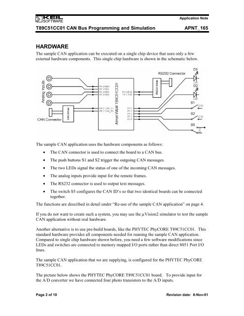
The sample CAN application can be executed on a single chip device that uses only a few<br />
external hardware components. This single chip hardware is shown in the schematic below.<br />
The sample CAN application uses the hardware components as follows:<br />
• The CAN connector is used to connect the board to a CAN bus.<br />
• The push buttons S1 and S2 trigger the outgoing CAN messages.<br />
• The two LEDs signal the status of one of the incoming CAN messages.<br />
• The analog inputs provide input for the remote frames.<br />
• The RS232 connector is used to output text messages.<br />
• The switch S5 configures the CAN ID’s so that two identical boards can be connected<br />
together.<br />
The functions are described in detail under “Re-use of the sample CAN application” on page 4.<br />
If you do not want to create such a system, you may use the µVision2 simulator to test the sample<br />
CAN application without real hardware.<br />
Another alternative is to use pre-build boards, like the PHYTEC PhyCORE T89C51CC01. This<br />
standard hardware provides all components needed for running the sample CAN application.<br />
Compared to single chip hardware shown before, you need a few software modifications since<br />
LEDs and switches are connected to memory mapped I/O ports rather than direct 8051 Port I/O<br />
lines.<br />
The sample CAN application that we are supplying, is configured for the PHYTEC PhyCORE<br />
T89C51CC01.<br />
The picture below shows the PHYTEC PhyCORE T89C51CC01 board. To provide input for<br />
the A/D converter we have connected four photo transistors to the A/D inputs.<br />
Page 2 of 10 Revision date: 8-Nov-01


