Tutorial 11 ChipscopePro, ISE 10.1 and Xilinx Simulator ... - Cosmiac
Tutorial 11 ChipscopePro, ISE 10.1 and Xilinx Simulator ... - Cosmiac
Tutorial 11 ChipscopePro, ISE 10.1 and Xilinx Simulator ... - Cosmiac

Create successful ePaper yourself
Turn your PDF publications into a flip-book with our unique Google optimized e-Paper software.
solely to verify the design in the <strong>ISE</strong> <strong>Simulator</strong>).<br />
The frequencies are controlled using input signal FREQUENCY connected to three of the available<br />
four sliding switches (SW1, SW2 & SW3).<br />
The output of the 4-bit counter is connected to four of the available seven LEDs (LD0, LD1, LD2,<br />
LD3).<br />
An asynchronous reset is also provided to the design which is connected to one of the sliding switches<br />
(SW0).<br />
Process<br />
1. Complete the counter design to implement functionality as explained (provided).<br />
2. Verify inputs <strong>and</strong> outputs with test bench waveform (provided).<br />
3. Integrate the ChipScope into the counter design (explained in detail in the Implementation<br />
section).<br />
4. Analyze the design using ChipScope (also explained in detailed in the next section).<br />
Implementation<br />
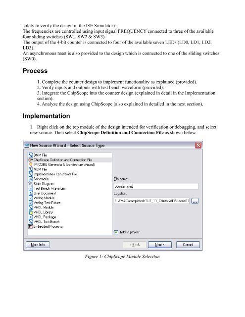
1. Right click on the top module of the design intended for verification or debugging, <strong>and</strong> select<br />
new source. Then select ChipScope Definition <strong>and</strong> Connection File as shown below.<br />
Figure 1: ChipScope Module Selection