FREQUENCY-CONVERTER MFR 600A / 1500A - PS Antriebstechnik
FREQUENCY-CONVERTER MFR 600A / 1500A - PS Antriebstechnik
FREQUENCY-CONVERTER MFR 600A / 1500A - PS Antriebstechnik

Create successful ePaper yourself
Turn your PDF publications into a flip-book with our unique Google optimized e-Paper software.
By means of a DIP-switch ( detailled description at 6.2 ) the drives can be switched to the following operation<br />
modes:<br />
In the ‘Normal - operation’ the frequency range reachesup to 150 Hz. In the low speed range the motor voltage<br />
can be increased by the adjustment of trimpot ‘Boost’ ( P1 ). The increase of the motor voltage causes at zero<br />
speed a DC-current in the motor. This DC-current provides braking down to zero speed and is automatically<br />
switched off 4 seconds after reaching zero frequency. This switch off is necessary to avoid heat-up of the motor<br />
at zero speed.<br />
In the ‘ Pump - operation’ - mode the maximum frequency reaches only 55 Hz and the ramp time is fix at<br />
5 sec. The trimpotis ‘ Boost’ and ‘Ramp’ are in this operation mode not active. In This mode the voltage to<br />
frequency - ratio is reduced with the frequency. This reduces the power - losses of the motor at reduced speeds.<br />
In the ‘High - frequency - operation’ - mode the maximum frequency - range reaches up to 600 Hz. In this<br />
mode the trimpot ‘boost’ is used to adjust the required voltage to frequency - ratio.<br />
In the operation - mode ‘ long ramp ‘ the ramp - time - adjustment - range is switched from 0.2-15 sec to<br />
4 - 300 sec ( for a frequency - step of 150 Hz / 600 Hz ). This Mode is not combinable with the pump-operation<br />
mode.<br />
The operation - mode ‘Motorpot’ enables to control the speed of the drive by 2 keys ( see 4.5 ).<br />
The operation - mode ‘200 Hz’ let the inverter automatically speed up to 200 Hz after switch on. The ramp-time<br />
is fixed to 1 sec, all control - signals and trimpotentiometers are inactive.<br />
The selection of the required operation - mode without voltage on the mains and inside the inverter. After<br />
disconnecting the drive from the mains the circuit needs appr. 30 sec to be free of voltage. After this time a<br />
switch from one to another operation - mode can be done.<br />
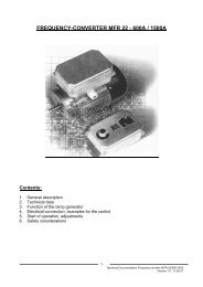
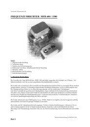
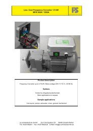
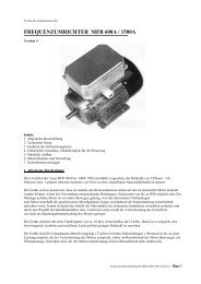
For the connections of the mains, motor and control lines there are plug - in - terminals used. To protect the<br />
drive against dust, humidity, mechanical shock and vibrations the electronic unit is embedded in a soft casting<br />
resin inside an aluminium case.<br />
The control - imputs of the drive are protection - isolated ( in accordance with VDE 0884 ). The drives are also<br />
protected against a direct short between motor - lines or between motor - line and earth.<br />
The electronic limiter of the motor - current allows at case temperatures up to 70°C a maximum motor -<br />
power of appr. 150 % of nominal power.<br />
The thermal - protection is switching off the drive at appr. 85°C. The reset of the thermal switch off must be<br />
done by switch off the mains for at least 10 sec.<br />
To control the drive signals from potentiometer, ext. voltage 0...10V, ext. current 0...20 mA or 4...20 mA are<br />
possible. The adaption of the input - circuit to correspond to the control - signal is made by the jumper B1<br />
and B2.<br />
Attention! If the input - circuit is set for control from a potentiometer or with 0...10 V, a disconnection of the<br />
control - input ( terminal 2 ) causes a control signal of half the adjusted maximum! Open control - input is<br />
therefore to be avoided.<br />
To enable the drive a closed loop must be connected to the enable - input.<br />
The temperature protection circuit of the motor is designed to accept loops with up to 1040 ohm as closed loops,<br />
higher resistance values as open loops. This makes it possible to use a PTC - sensor or a thermistor<br />
in the motor.<br />
The drive delivers an output signal (Inverter OK) if mains is ok and no error is detected.<br />
Control - lines with a length of more than 2 meters must be shielded. The shield should be connected to<br />
terminal 4. Below the length of 2 meters shielding is recommanded if a high disturbance - level is present in the<br />
surrounding.<br />
Technical description for <strong>MFR</strong> 600/1500 2