frequency-converter mfr 22 - 600a / 1500a - PS Antriebstechnik
frequency-converter mfr 22 - 600a / 1500a - PS Antriebstechnik
frequency-converter mfr 22 - 600a / 1500a - PS Antriebstechnik

You also want an ePaper? Increase the reach of your titles
YUMPU automatically turns print PDFs into web optimized ePapers that Google loves.
Contents:<br />
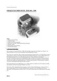
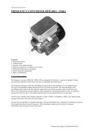
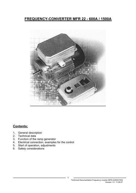
FREQUENCY-CONVERTER MFR <strong>22</strong> - 600A / 1500A<br />
1. General description<br />
2. Technical data<br />
3. Function of the ramp generator<br />
4. Electrical connection, examples for the control<br />
5. Start of operation, adjustments<br />
6. Safety considerations<br />
1<br />
Technical Documentation Frequency inverter MFR-<strong>22</strong>/600/1500<br />
Version 1.0 11.09.07
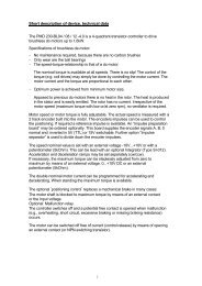
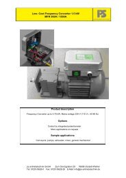
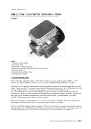
1. General description<br />
The <strong>frequency</strong> <strong>converter</strong> MDC-12.004/005-AS are designed for the speed - variation of<br />
standard 3-phase asynchronous induction motors from zero up to an adjustable maximum<br />
speed. The unit has a universal serial interface providing the connection of a control unit (<br />
PG 1) or a bus-interface. Setting and changing of all parameters must be made by the<br />
control-unit or by the connected bus. The parameters are stored in a non volatile memory .<br />
The mechanical design provides the assembling instead of the normal terminal case of a<br />
standard motor. By use of corresponding sealings protection levels up to IP68 are<br />
possible. The main advantage of the assembling on the motor is the fact, that the<br />
connections to the motor are inside of the closed metal case. This is very important<br />
because the radiation of this connections is prohibited and there is also no capacitive load<br />
for the inverter to drive. This reduces both the power losses and the RFI level on the<br />
mains.<br />
The drives are working with a chopper <strong>frequency</strong> of appr. 10 kHz, providing smooth<br />
running of the motor also in the low speed region.<br />
The drives are designed for 2-quadrant operation (driving in both directions). Braking is<br />
possible up to a power level equal to the power losses of the motor. While braking the<br />
induction of the motor is increased and therefore also the power losses of the motor.<br />
The setting of the parameters include the selection of the following operation modes:<br />
In the ‘Normal - operation’ the <strong>frequency</strong> range reaches up to 150 Hz. In the low speed<br />
range the motor voltage can be increased by the setting of a boost-value ( 0…99%). The<br />
increase of the motor voltage causes at zero speed a DC-current in the motor. This DCcurrent<br />
provides braking down to zero speed and is automatically switched off 4 seconds<br />
after reaching zero <strong>frequency</strong>. This switch off is necessary to avoid heat-up of the motor<br />
at zero speed.<br />
In the ‘High - <strong>frequency</strong> - operation’ - mode the maximum <strong>frequency</strong> - range reaches up<br />
to 300 Hz.<br />
In the operation - mode ‘ long ramp ‘ the ramp - time - adjustment - range is switched<br />
from 0.2-15 sec to 4 - 300 sec ( for a <strong>frequency</strong> - step of 150 Hz / 300 Hz ).<br />
The operation - mode ‘Motorpot’ enables to control the speed of the drive by 2 keys<br />
(see 4.5).<br />
Selection of the ‘Enable’ – function in addition to any operation mode prevent the inverter<br />
from self – starting. After switch on or an error the inverter must be enabled by switching<br />
the enable input.<br />
2<br />
Technical Documentation Frequency inverter MFR-<strong>22</strong>/600/1500<br />
Version 1.0 11.09.07
The operation - mode ‘200 Hz’ let the inverter automatically speed up to 200 Hz after<br />
switch on. The ramp-time is fixed to 1 sec, all control - signals and trim-potentiometers are<br />
inactive.<br />
The selection of the required operation - mode and the parameters must be done in the<br />
presence of mains-voltage. After disconnection of the mains the parameters are stored in<br />
the non-volatile memory of the inverter.<br />
For the connections of the mains, motor and control lines there are plug - in - terminals<br />
used. To protect the drive against dust, humidity, mechanical shock and vibrations the<br />
electronic unit is embedded in a soft casting resin inside an aluminium case.<br />
The control - inputs of the drive are protection - isolated (in accordance with VDE 0884).<br />
The drives are also protected against a direct short between motor - lines or between<br />
motor - line and earth.<br />
The electronic limiter of the motor - current allows at case - temperatures below 30°C a<br />
maximum motor - power of appr. 150 % of nominal power. At higher temperatures the<br />
maximum power is reduced to appr. 120 % of nominal power at 80°C case - temperature.<br />
The thermal - protection is switching off the drive at appr. 85°C. The reset of the thermal<br />
spitch off must be done by switch off the mains for at least 10 sec.<br />
To control the drive signals from potentiometer, ext. voltage 0...10V, ext. current 0...20mA<br />
or 4...20mA are possible. The adaption of the input - circuit to correspond to the control -<br />
signal is made by the jumper B1 and B2.<br />
Attention! If the input - circuit is set for control from a potentiometer or with 0...10 V,<br />
a disconnection of the control - input (terminal 2) causes a control signal of half the<br />
adjusted maximum! Open control - input is therefore to be avoided.<br />
To enable the drive a closed loop must be connected to the enable - input. The circuit is<br />
designed to accept loops with up to 1 kOhm as closed loops, higher resistance values as<br />
open loops. This makes it possible to include a PTC - sensor of the motor in the enable -<br />
loop.<br />
Control - lines with a length of more than 2 meters must be shielded. The shield should be<br />
connected to terminal 4. Below the length of 2 meters shielding is recommended if a high<br />
disturbance - level is present in the surrounding.<br />
3<br />
Technical Documentation Frequency inverter MFR-<strong>22</strong>/600/1500<br />
Version 1.0 11.09.07
2. Technical Data<br />
4<br />
MDC-12.004-AS MDC-12.005-AS<br />
Mains - voltage 230V AC;115V AC o.r. 230V AC; 115VAC o.r.<br />
Tolerance of the mains-voltage +/- 15% +/- 15%<br />
Frequency of the mains-voltage 50 – 60 Hz 50 – 60 Hz<br />
Recommended fuse in the mains 6,3A slow 10A slow<br />
Rec. max. motor size 375 Watt 550 Watt<br />
Nominal voltage of the motor 3x230V AC 3x230V AC<br />
Motor-current (max. at 30°C case-temp.) 3A RMS 5,5A RMS<br />
(max. at 80°C case-temp.) 2,4 A RMS 4,4A RMS<br />
Temperature-range (case-temperature) 0 – 80°C 0 – 80°C<br />
Mechanical size (LxBxT) [mm] 150x100x70 150x100x70<br />
Weight [kg]<br />
Output - <strong>frequency</strong> - ranges:<br />
0,85 0,88<br />
• Normal – operation 0 - 150 Hz<br />
• High - <strong>frequency</strong> – operation<br />
0 - 300 Hz<br />
Adjustment - range of the min. <strong>frequency</strong><br />
0-50% of the pre-adjusted maximum<br />
Ramp - times:<br />
Normal-operation, <strong>frequency</strong>-step=150Hz<br />
• With short ramp 0,2 – 15 sec<br />
• With long ramp 4 – 300 sec<br />
High-<strong>frequency</strong>-mode, freq. step = 600Hz<br />
• With short ramp 0,2 – 15 sec<br />
• With long ramp 4 – 300 sec<br />
Pump-operation-mode, freq. step = 55 Hz 5 sec<br />
200 Hz – Operation - mode 1 sec<br />
Control - signals:<br />
• B1 and B2 open Potentiometer or ext. voltage 0-10V<br />
• B1 closed, B2 open 0-20mA<br />
• B1 and B2 closed 4-20mA<br />
Input-resistance of the control-input:<br />
B1 open >500kOhm<br />
B1 closed 470 Ohm<br />
Enable - signal: closed loop with less than 1 kohm<br />
current in the enable - loop 10V/1mA DC<br />
Reversing - signal: open / closed loop, 10 V / 1mA DC<br />
Technical Documentation Frequency inverter MFR-<strong>22</strong>/600/1500<br />
Version 1.0 11.09.07
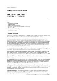
3. Function of the ramp - generator<br />
3.1 Normal - or high - <strong>frequency</strong> - operation - mode::<br />
Frequency<br />
setting<br />
Output<br />
<strong>frequency</strong><br />
t t Time<br />
Acceleration time and deceleration time can be programmed individual.<br />
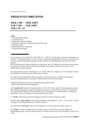
4. Electrical connection and examples for the control of the drive<br />
4.1 Control by potentiometer:<br />
4.2 Control by external voltage 0...10 V DC:<br />
5<br />
Time<br />
Technical Documentation Frequency inverter MFR-<strong>22</strong>/600/1500<br />
Version 1.0 11.09.07
4.3 Control by external current 0...20mA DC ( 4 ... 20mA DC ):<br />
4.4 Use of the enable-loop to provide 4.5 control by 2 keys<br />
thermal protection of the motor: in the mode `Motorpot`:<br />
6<br />
Technical Documentation Frequency inverter MFR-<strong>22</strong>/600/1500<br />
Version 1.0 11.09.07
5. Start of operation, adjustments<br />
Because of the fact, that an adjustment is impossible if the drive is assembled, parameters<br />
and limits must be adjusted before assembling.<br />
It is recommended to make the requ. adjustments within the incoming inspection.<br />
For OEM applications we offer as a special service without additional costs to make the<br />
adjustments within the final inspections in our house.<br />
5.1 Position of the jumpers:<br />
Prior to the assembling there is only the selection of the desired control signal necessary:<br />
B1 inserted, B2 not inserted:<br />
Control by current 0…20mA DC<br />
B1 and B2 not inserted:<br />
Control by voltage 0…10V DC or potentiometer<br />
B1 and B2 inserted:<br />
Control by current 4…20mA DC<br />
7<br />
Technical Documentation Frequency inverter MFR-<strong>22</strong>/600/1500<br />
Version 1.0 11.09.07
6. Safety considerations<br />
The following safety considerations must be observed during all phases of operation,<br />
service and repair of this device. Failure to comply with this precautions violates the<br />
intended use of this device.<br />
To minimize the shock - hazard the drive must be connected to an electrical ground.<br />
Terminal PE or the metal-case must be connected to the electrical ground ( safety -<br />
ground ) of the power - outlet.<br />
Do not operate in an explosive atmosphere!<br />
Operation of this device in the presence of flammable gases, fumes or dusts may cause of<br />
an ignition of this atmosphere and is to prevent.<br />
CAUTION!<br />
To prevent potential shock hazards do not expose this device in the open state to<br />
moisture, rain or wetness. Wetness inside the case may cause an electrical connection<br />
between mains and the inputs.<br />
Installation, adjustment and service of this device must be made by qualified personal.<br />
Works at the electrical parts of the device are very dangerous because of the high voltage<br />
the device is working with. This high voltage is capable of causing death and is present<br />
even after disconnecting mains. Before starting of service it is necessary<br />
to wait at least 30 sec. after disconnecting mains.<br />
This device must not used as an electrical disconnection. It is not allowed to work at the<br />
output lines without a mechanical disconnection from mains, even if the driven motor does<br />
not carry voltage or current.<br />
Do not attempt internal service or adjustment unless another person, capable of<br />
disconnecting mains and rendering first aid is present.<br />
Do not touch the electrical parts of this device. During operation the electrical parts are<br />
carrying dangerous voltages. Out of operation a touch may cause a defect by electrostatic<br />
discharge.<br />
To prevent additional hazards, do not make modifications at this device.<br />
8<br />
Technical Documentation Frequency inverter MFR-<strong>22</strong>/600/1500<br />
Version 1.0 11.09.07