frequency-converter mfr 22 - 600a / 1500a - PS Antriebstechnik
frequency-converter mfr 22 - 600a / 1500a - PS Antriebstechnik
frequency-converter mfr 22 - 600a / 1500a - PS Antriebstechnik

Create successful ePaper yourself
Turn your PDF publications into a flip-book with our unique Google optimized e-Paper software.
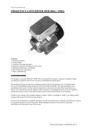
1. General description<br />
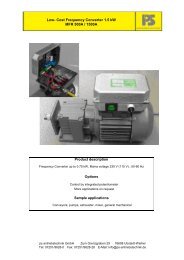
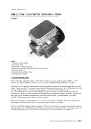
The <strong>frequency</strong> <strong>converter</strong> MDC-12.004/005-AS are designed for the speed - variation of<br />
standard 3-phase asynchronous induction motors from zero up to an adjustable maximum<br />
speed. The unit has a universal serial interface providing the connection of a control unit (<br />
PG 1) or a bus-interface. Setting and changing of all parameters must be made by the<br />
control-unit or by the connected bus. The parameters are stored in a non volatile memory .<br />
The mechanical design provides the assembling instead of the normal terminal case of a<br />
standard motor. By use of corresponding sealings protection levels up to IP68 are<br />
possible. The main advantage of the assembling on the motor is the fact, that the<br />
connections to the motor are inside of the closed metal case. This is very important<br />
because the radiation of this connections is prohibited and there is also no capacitive load<br />
for the inverter to drive. This reduces both the power losses and the RFI level on the<br />
mains.<br />
The drives are working with a chopper <strong>frequency</strong> of appr. 10 kHz, providing smooth<br />
running of the motor also in the low speed region.<br />
The drives are designed for 2-quadrant operation (driving in both directions). Braking is<br />
possible up to a power level equal to the power losses of the motor. While braking the<br />
induction of the motor is increased and therefore also the power losses of the motor.<br />
The setting of the parameters include the selection of the following operation modes:<br />
In the ‘Normal - operation’ the <strong>frequency</strong> range reaches up to 150 Hz. In the low speed<br />
range the motor voltage can be increased by the setting of a boost-value ( 0…99%). The<br />
increase of the motor voltage causes at zero speed a DC-current in the motor. This DCcurrent<br />
provides braking down to zero speed and is automatically switched off 4 seconds<br />
after reaching zero <strong>frequency</strong>. This switch off is necessary to avoid heat-up of the motor<br />
at zero speed.<br />
In the ‘High - <strong>frequency</strong> - operation’ - mode the maximum <strong>frequency</strong> - range reaches up<br />
to 300 Hz.<br />
In the operation - mode ‘ long ramp ‘ the ramp - time - adjustment - range is switched<br />
from 0.2-15 sec to 4 - 300 sec ( for a <strong>frequency</strong> - step of 150 Hz / 300 Hz ).<br />
The operation - mode ‘Motorpot’ enables to control the speed of the drive by 2 keys<br />
(see 4.5).<br />
Selection of the ‘Enable’ – function in addition to any operation mode prevent the inverter<br />
from self – starting. After switch on or an error the inverter must be enabled by switching<br />
the enable input.<br />
2<br />
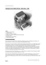
Technical Documentation Frequency inverter MFR-<strong>22</strong>/600/1500<br />
Version 1.0 11.09.07