Operating Manual for Hot runner Nozzles Thermoject® - psg-online.de
Operating Manual for Hot runner Nozzles Thermoject® - psg-online.de
Operating Manual for Hot runner Nozzles Thermoject® - psg-online.de

Create successful ePaper yourself
Turn your PDF publications into a flip-book with our unique Google optimized e-Paper software.
<strong>Operating</strong> <strong>Manual</strong> <strong>for</strong> <strong>Hot</strong> <strong>runner</strong> <strong>Nozzles</strong> <strong>Thermoject®</strong><br />
Mini-Series 2022-Version-B<br />
Uni-Series 2026/2040-Version-B<br />
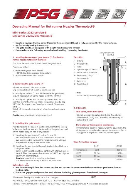
• Nozzle is equipped with a screw thread in the gate insert (7) and is fully assembled by the manufacturer.<br />
• No further tightening is necessary.<br />
• The gate inserts are equipped with a right-hand screw fine-thread!<br />
• Please refer to the following manual when installing / removing the <strong>de</strong>vice.<br />
Apply tension here<br />
(point 2)<br />
1. Installing/Removing of gate inserts (7) <strong>for</strong> the <strong>Hot</strong><br />
<strong>runner</strong> nozzle installed in the toole<br />
First draw the mold plate down to reach the gate inserts.<br />
Please note be<strong>for</strong>e!<br />
1. <strong>Hot</strong> <strong>runner</strong> system must be cold.<br />
100°C below the processing temperature.<br />
2. Anti-rotation dowel must be exist.<br />
2. Removing the gate inserts (7)<br />
It is not necessary to take apart nozzle.<br />
Grip the nozzle body (2) in soft V blocks an a vise.<br />
In case of gate variants O1 and R1 dismantle the gate insert<br />
cold. (If necessary heat up the nozzle to 100°C - 150°C ).<br />
In case of gate style R3 and O3 heat up the nozzle to 200°C<br />
and than dismantle. Increase nozzle temperature step by step<br />
till 350°C, if the gate doesn´t easily turn round. (Torque see<br />
table 1).<br />
Switch off the nozzles immediately after dismantling the gate<br />
insert.<br />
Caution: pay attention to safety instructions!<br />
3. Installing the gate inserts<br />
Prior to installing the <strong>de</strong>vice it must be ensured that the sealing<br />
surfaces on the front si<strong>de</strong> and the threads on the gate insert and<br />
on the nozzle body are free of any plastics.<br />
3.1<br />
3.2<br />
Installing the gate inserts (CU-alloy) O1 and R1.<br />
This may only be done in a cold condition of the <strong>de</strong>vices.<br />
We recommend to conduct the installation using a torque<br />
spanner with a torque seen at the table 1.<br />
Installing the gate inserts (thermally implanted molyb<strong>de</strong>num<br />
alloy) O3 and R3.<br />
Screw-in only in cold condition; tighten with a torque seen in<br />
table 1. Then heat-up nozzle minimum to 350 °C and tighten<br />
again with a same torque.<br />
Caution: pay attention to safety instructions!<br />
It is advisable to use a torque wrench <strong>for</strong> insatllation.<br />
Parts List:<br />
1 O-Ring<br />
2 Nozzle body<br />
3 Case<br />
4 Cylindrical pin Ø 3m6x8<br />
5 Anti-rotation dowel Ø8<br />
6 Heater with integr.<br />
thermocouple<br />
7 Gate insert<br />
8 Nozzle head<br />
Hint:<br />
Do not use any installing sprays!<br />
4. O-Ring (1)<br />
- Trial series, short-time series<br />
It is not necessary to replace the O-ring if no plastics<br />
infiltrated the O-ring slot. Otherwise, it is necessary to<br />
replace the O-ring!<br />
- During longer lasting serial production<br />
If maintenance becomes necessary <strong>for</strong> the equipment, the<br />
O-rings are to be replaced as a preventive measure. This is<br />
also applies if no plastics infiltrated the O-ring slot.<br />
Table 1: Starting torques<br />
Temperature<br />
Safety hint: !<br />
• <strong>Hot</strong> fusion can spill from hot <strong>runner</strong> nozzles and systems in an uncontrolled manner from gate insert slots or<br />
feeding slots.<br />
• Protective goggles and protective work clothes (including gloves) protect from health damages.<br />
O1/R1<br />
We reserve the right to make technical changes<br />
11/05<br />
PSG Plastic Service GmbH • Postfach 42 01 62 • D-68280 Mannheim<br />
Telefon +49-621/7162-0 • Telefax +49-621/7162-162 • www.<strong>psg</strong>-<strong>online</strong>.<strong>de</strong> • info@<strong>psg</strong>-<strong>online</strong>.<strong>de</strong><br />
2022<br />
2026<br />
2040<br />
cold<br />
10 Nm<br />
20 Nm<br />
55 Nm<br />
O3/R3<br />
350°C<br />
15 Nm<br />
25 Nm<br />
80 Nm<br />
drawn out<br />
of position!
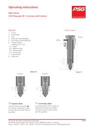
5. Installing/removing the nozzle during replacement<br />
oh heater<br />
The fundamental handling - (see fig.1-3).<br />
Only with the Uni-series the cable attachment is to be<br />
removed. Besi<strong>de</strong> the basic <strong>de</strong>vice one needs the<br />
assembly/disassembly set. Thus the housing (3) is pushed<br />
by the nozzle body (2) - (see fig.1+2).<br />
The ingate employment (7) remains thereby in the nozzle.<br />
The disassembly of the heater is facilitated through <strong>for</strong><br />
tricks against the turn direction, when simultaneous<br />
pushing.<br />
Picture 1:<br />
Picture 2:<br />
Picture 3:<br />
6. Further hints<br />
Main <strong>de</strong>vice<br />
Removal tools<br />
Installing tools<br />
In the case of use of normal ring spanners it can come<br />
<strong>de</strong>pending up on energy expenditure to the <strong>de</strong><strong>for</strong>mation of<br />
the gate insert!<br />
We recommend to work generally with a torque wrench.<br />
7. Special tools <strong>for</strong> easier service<br />
7.2 Installing-/Removal tools<br />
Main <strong>de</strong>vice - <strong>de</strong>vice no. 265760<br />
Installing-/Removal tools<br />
For Thj 2022<br />
For Thj 2026<br />
For Thj 2040<br />
7.3 Drawout <strong>de</strong>vice<br />
Drawout <strong>de</strong>vice<br />
For Thj 2022<br />
For Thj 2026<br />
For Thj 2040<br />
Art.-No.<br />
290 472<br />
291 571<br />
291 572<br />
Art.-No.<br />
290 477<br />
291 581<br />
291 582<br />
The drawout <strong>de</strong>vice facilitates the <strong>de</strong>velopment of the hot<br />
<strong>runner</strong> nozzle from the tool. See fig. 4-7.<br />
Picture 4:<br />
Picture 5: Picture 6: Picture 7: