unit 1 metal cutting and chip formation - IGNOU
unit 1 metal cutting and chip formation - IGNOU
unit 1 metal cutting and chip formation - IGNOU

You also want an ePaper? Increase the reach of your titles
YUMPU automatically turns print PDFs into web optimized ePapers that Google loves.
Theory of Metal Cutting<br />
14<br />
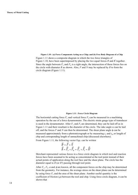
Figure 1.10 : (a) Force Components Acting on a Chip; <strong>and</strong> (b) Free Body Diagram of a Chip<br />
Figure 1.11 shows a composite diagram in which the two force triangles of<br />
Figure 1.10, have been superimposed by placing the two equal forces R <strong>and</strong> R ' together.<br />
Since the angle between Fs <strong>and</strong> Fn is a right angle, the intersection of these forces lies on<br />
the circle with diameter R as shown. Also, F <strong>and</strong> N may be replaced by R to form the<br />
circle diagram (Figure 1.11).<br />
Figure 1.11 : Force Circle Diagram<br />
The horizontal <strong>cutting</strong> force Fc <strong>and</strong> vertical force Ft can be measured in a machining<br />
operation by the use of a force dynamometer. The electric strain gauge type of transducer<br />
is used in the dynamometer. After Fc <strong>and</strong> Ft are determined, they can be laid off as in<br />
Figure 1.11 <strong>and</strong> their resultant is the diameter of the circle. The rake angle α can be laid<br />
off, <strong>and</strong> the forces F <strong>and</strong> N can then be determined. The shear plane angle φ can be<br />
measured approximately from a photomicrograph or by measuring tc <strong>and</strong> tu, or length of<br />
<strong>chip</strong> <strong>and</strong> corresponding length of unmachined <strong>chip</strong> (discussed elsewhere).<br />
From Figure 1.11, the following vector Eqs. can be written<br />
ρ ρ ρ<br />
R'<br />
= F + N<br />
ρ ρ ρ ρ ρ ρ<br />
R = Fs<br />
+ Fn<br />
= Fc<br />
+ Ft<br />
= R'<br />
Merchant represented various forces in a force circle diagram in which tool <strong>and</strong> reaction<br />
forces have been assumed to be acting as concentrated at the tool point instead of their<br />
actual points of application along the tool face <strong>and</strong> the shear plane. The circle has the<br />
diameter equal to R (or R') passing through tool point.<br />
After Fc, Ft, α <strong>and</strong> φ are known, all the component forces on the <strong>chip</strong> may be determined<br />
from the geometry. For instance, the average stress on the shear plane can be determined<br />
by using force Fs <strong>and</strong> the area of the shear plane. Another useful quantity is the<br />
coefficient of friction (μ) between the tool <strong>and</strong> <strong>chip</strong>. Using force circle diagram, it can be<br />
shown that