RT3 STRAIGHT BLADE INSTALLATION MANUAL - Boss Products
RT3 STRAIGHT BLADE INSTALLATION MANUAL - Boss Products
RT3 STRAIGHT BLADE INSTALLATION MANUAL - Boss Products

You also want an ePaper? Increase the reach of your titles
YUMPU automatically turns print PDFs into web optimized ePapers that Google loves.
Electrical System Wiring Procedure<br />
NOTICE<br />
Before splicing into any electrical circuit, identify<br />
the circuit with a test lamp. Failure to test circuits<br />
may result in vehicle damage.<br />
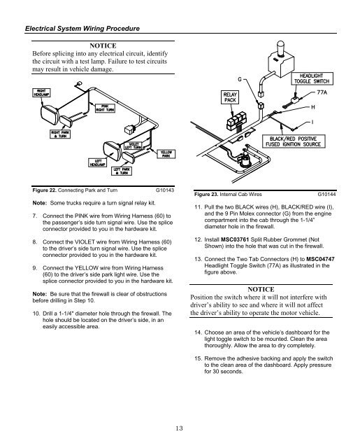
Figure 22. Connecting Park and Turn G10143<br />
Note: Some trucks require a turn signal relay kit.<br />
7. Connect the PINK wire from Wiring Harness (60) to<br />
the passenger’s side turn signal wire. Use the splice<br />
connector provided to you in the hardware kit.<br />
8. Connect the VIOLET wire from Wiring Harness (60)<br />
to the driver’s side turn signal wire. Use the splice<br />
connector provided to you in the hardware kit.<br />
9. Connect the YELLOW wire from Wiring Harness<br />
(60) to the driver’s side park light wire. Use the<br />
splice connector provided to you in the hardware kit.<br />
Note: Be sure that the firewall is clear of obstructions<br />
before drilling in Step 10.<br />
10. Drill a 1-1/4" diameter hole through the firewall. The<br />
hole should be located on the driver’s side, in an<br />
easily accessible area.<br />
13<br />
Figure 23. Internal Cab Wires G10144<br />
11. Pull the two BLACK wires (H), BLACK/RED wire (I),<br />
and the 9 Pin Molex connector (G) from the engine<br />
compartment into the cab through the 1-1/4”<br />
diameter hole in the firewall.<br />
12. Install MSC03761 Split Rubber Grommet (Not<br />
Shown) into the hole that was cut in the firewall.<br />
13. Connect the Two Tab Connectors (H) to MSC04747<br />
Headlight Toggle Switch (77A) as illustrated in the<br />
figure above.<br />
NOTICE<br />
Position the switch where it will not interfere with<br />
driver’s ability to see and where it will not affect<br />
the driver’s ability to operate the motor vehicle.<br />
14. Choose an area of the vehicle’s dashboard for the<br />
light toggle switch to be mounted. Clean the area<br />
thoroughly. Allow the area to dry completely.<br />
15. Remove the adhesive backing and apply the switch<br />
to the clean area of the dashboard. Apply pressure<br />
for 30 seconds.