RT3 STRAIGHT BLADE INSTALLATION MANUAL - Boss Products
RT3 STRAIGHT BLADE INSTALLATION MANUAL - Boss Products
RT3 STRAIGHT BLADE INSTALLATION MANUAL - Boss Products

Create successful ePaper yourself
Turn your PDF publications into a flip-book with our unique Google optimized e-Paper software.
Electrical System Wiring Procedure<br />
NOTICE<br />
Be sure the wire loom does not interfere with the<br />
operation of the vehicle’s pedals.<br />
16. Secure the 9 Pin Molex Connector (G) and wire<br />
loom underneath the dashboard.<br />
17. Plug the controller into the 9 Pin Molex Connector<br />
(G).<br />
18. Mount the plow control in a location that is<br />
comfortable for the operator to reach, and where the<br />
operator will not contact the control in the event of a<br />
crash. (See “Straight Blade Controller Mounting<br />
Instructions” located in this manual.)<br />
19. Connect the BLACK/RED wire (I) to a “keyed” 12V+<br />
ignition source.<br />
Note: This 12V+ source should only be active when the<br />
key is in the ON position. Failure to wire to a “keyed”<br />
source can allow a condition to occur causing the<br />
battery to drain.<br />
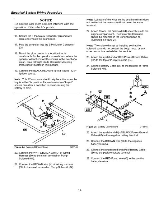
Figure 24. Solenoid Connections. G10145<br />
20. Connect the WHITE/BLACK wire (J) of Wiring<br />
Harness (60) to the small terminal on Pump<br />
Solenoid (64).<br />
21. Connect the BROWN wire (K) of Wiring Harness<br />
(60) to the small terminal on Pump Solenoid (64).<br />
14<br />
Note: Location of the wires on the small terminals does<br />
not matter but the wires should not be on the same<br />
terminal.<br />
22. Attach Power Unit Solenoid (64) securely inside the<br />
engine compartment. The Power Unit Solenoid<br />
should be mounted in the upright position as<br />
illustrated in Figure 24.<br />
Note: The solenoid must be installed so that the<br />
solenoid posts do not contact the body, hood, or any<br />
other conductive material on the vehicle.<br />
23. Attach the eyelet end of RED Power/Ground Cable<br />
(62) to the top of Pump Solenoid (64).<br />
24. Connect Battery Cable (66) to the top post of Pump<br />
Solenoid (64).<br />
Figure 25. Battery Connections G10146<br />
25. Attach the eyelet end (N) of BLACK Power/Ground<br />
Cable (62) to the negative battery terminal.<br />
26. Connect the BROWN wire (Q) to the negative<br />
battery terminal.<br />
27. Connect the unattached end (P) of Battery Cable<br />
(66) to the positive battery terminal.<br />
28. Connect the RED Fused wire (O) to the positive<br />
battery terminal.