Pascal Delapierre's Article on Keels
Pascal Delapierre's Article on Keels
Pascal Delapierre's Article on Keels

Create successful ePaper yourself
Turn your PDF publications into a flip-book with our unique Google optimized e-Paper software.
Keel proporti<strong>on</strong>s<br />
(translati<strong>on</strong> and completi<strong>on</strong> of article Fra-19, available in French and Spanish)<br />
The Argentine fleet are certainly the largest RG65 fleet, arguably <strong>on</strong>e where competiti<strong>on</strong><br />
would have let evoluti<strong>on</strong> laws rule, and I was very surprised to see how little draught they had.<br />
I therefore attempted a set of calculati<strong>on</strong>s to review this against theory.<br />
After a few attempts, I eventually c<strong>on</strong>cluded that a sensible criteri<strong>on</strong> for the analysis was the<br />
submerged fr<strong>on</strong>t surface of the model, i.e. taking into account its hull, keel and ballast. This<br />
assumes that the drag coefficient of all three elements is “comparable”, will come back to this<br />
in c<strong>on</strong>clusi<strong>on</strong>.<br />
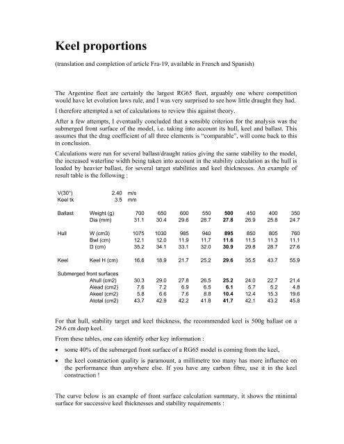
Calculati<strong>on</strong>s were run for several ballast/draught ratios giving the same stability to the model,<br />
the increased waterline width being taken into account in the stability calculati<strong>on</strong> as the hull is<br />
loaded by heavier ballast, for several target stabilities and keel thicknesses. An example of<br />
result table is the following :<br />
V(30°) 2.40 m/s<br />
Keel tk 3.5 mm<br />
Ballast Weight (g) 700 650 600 550 500 450 400 350<br />
Dia (mm) 31.1 30.4 29.6 28.7 27.8 26.9 25.8 24.7<br />
Hull W (cm3) 1075 1030 985 940 895 850 805 760<br />
Bwl (cm) 12.1 12.0 11.9 11.7 11.6 11.5 11.3 11.1<br />
D (cm) 35.2 34.1 33.1 32.0 30.9 29.8 28.7 27.6<br />
Keel Keel H (cm) 16.6 18.9 21.7 25.2 29.6 35.5 43.7 55.9<br />
Submerged fr<strong>on</strong>t surfaces<br />
Ahull (cm2) 30.3 29.0 27.8 26.5 25.2 24.0 22.7 21.4<br />
Alead (cm2) 7.6 7.2 6.9 6.5 6.1 5.7 5.2 4.8<br />
Akeel (cm2) 5.8 6.6 7.6 8.8 10.4 12.4 15.3 19.6<br />
Atotal (cm2) 43.7 42.9 42.2 41.8 41.7 42.1 43.2 45.8<br />
For that hull, stability target and keel thickness, the recommended keel is 500g ballast <strong>on</strong> a<br />
29.6 cm deep keel.<br />
From these tables, <strong>on</strong>e can identify other key informati<strong>on</strong> :<br />
• some 40% of the submerged fr<strong>on</strong>t surface of a RG65 model is coming from the keel,<br />
• the keel c<strong>on</strong>structi<strong>on</strong> quality is paramount, a millimetre too many has more influence <strong>on</strong><br />
the performance than anywhere else. If you have any carb<strong>on</strong> fibre, use it in the keel<br />
c<strong>on</strong>structi<strong>on</strong> !<br />
The curve below is an example of fr<strong>on</strong>t surface calculati<strong>on</strong> summary, it shows the minimal<br />
surface for successive keel thicknesses and stability requirements :
This family of curves is based <strong>on</strong> stability formulae published within article<br />
http://navi.modelisme.com/article135.html, completed to calculate the submerged fr<strong>on</strong>t<br />
surfaces. Such diagram was produced for successive keel thicknesses.<br />
The ballast weight / keel depth pairs providing minimal fr<strong>on</strong>t surface for a given stability was<br />
finally presented in a single diagram, with keel thickness as additi<strong>on</strong>al parameter:<br />
The blue lines are the iso-stability curves.
The calculati<strong>on</strong>s were made <strong>on</strong> three hull forms, 11, 12 and 14cm wide. The optimal pairs<br />
proved almost independent from the hull, the keel can therefore be selected before the hull…<br />
These calculated optimal pairs propose deeper keels than certain Argentine <strong>on</strong>es, but the study<br />
clearly shows that draught cannot be increased forever. Finally, short keels still need to<br />
provide side surface, they become thicker when their chord increase …<br />
How much stability do you need ?<br />
The above calculati<strong>on</strong>s also show the cost for stability. The results using Colombine as<br />
example :<br />
Stability (V30)<br />
Fr<strong>on</strong>tal surface<br />
(3.25mm keel)<br />
Corresp<strong>on</strong>ding lead weight<br />
and keel depth<br />
2.3 m/s 39.0 cm2 475 g – 26.5 cm<br />
2.5 m/s 41.7 cm2 550 g – 27.5 cm<br />
2.7 m/s 44.4 cm2 600 g – 30.5 cm<br />
Here again, several schools of thought co-exist ; In Brazil, ballast weights of 650g or more are<br />
comm<strong>on</strong>, in Argentine, the models seem less and less stable (ref. JIF2).<br />
I currently plan to design against a 3.25mm keel thickness, and adopted :<br />
• a 500g ballast with a keel height of 27cm, and<br />
• a 650g ballast with a keel height of 33cm.<br />
Three rigs and two keels, we have six gears to our model. An example of gearbox balance:
C<strong>on</strong>structi<strong>on</strong><br />
If you have carb<strong>on</strong> fibre, I<br />
recommend using it all for the<br />
keel; it is not essential for the<br />
hull.<br />
I build my keel fins from a<br />
1.5mm wood core, <strong>on</strong> which I<br />
resin two layers of carb<strong>on</strong> and<br />
fibreglass <strong>on</strong> each side. The<br />
wood core is cut 1cm narrower<br />
than the final keel chord to<br />
allow the two fibre skins to<br />
join at the edges.<br />
The whole set is pressed<br />
together while curing.<br />
The 500g selecti<strong>on</strong> is<br />
especially sexy, as it doe not<br />
require to turn into a<br />
alchemist to get <strong>on</strong>e : it is<br />
available from stock in many<br />
fishing shops as “macquerel<br />
lead”. A few hammer fairing<br />
bangs, putty and you are there<br />
I perform attachment o the keel via a steel wire<br />
« staple » :A<br />
1. Hammer down a 5 to 8mm groove with a<br />
screwdriver head in the middle of the bulb.<br />
2. Make a “U” shape in a steel wire and clue it with<br />
epoxy into the groove, the two ends should<br />
protrude 1cm minimum and be parallel.<br />
3. Present the two ends to the keel wing and mark<br />
the positi<strong>on</strong>s to be drilled<br />
4. Glue the two steel wire ends into the keel wing<br />
with epoxy.<br />
The final product is meant to look like this…
C<strong>on</strong>clusi<strong>on</strong><br />
The assumpti<strong>on</strong> that all three forms, hull, ballast and keel have the same drag coefficient is<br />
certainly false, but I failed to find sensible literature <strong>on</strong> the subject. Remember that we sail in<br />
the laminar phase for the keel, and transiti<strong>on</strong> z<strong>on</strong>e for the hull, it’s all black art… Should you<br />
have reas<strong>on</strong>s to believe that the keel is x% more drag for the same fr<strong>on</strong>tal surface than the rest,<br />
you just need to multiply the keel thickness by the same x% before using the curves.