Sails: The Source of Power - American Model Yachting Association
Sails: The Source of Power - American Model Yachting Association
Sails: The Source of Power - American Model Yachting Association

Create successful ePaper yourself
Turn your PDF publications into a flip-book with our unique Google optimized e-Paper software.
<strong>Sails</strong>: <strong>The</strong> <strong>Source</strong> <strong>of</strong> <strong>Power</strong><br />
An Introduction to<br />
<strong>Model</strong> Yacht <strong>Sails</strong>, Part 1<br />
by Rod Carr<br />
<strong>The</strong> first job <strong>of</strong> a new skipper is to<br />
learn the specific nomenclature<br />
that describes the sails. <strong>The</strong>re<br />
are a handful <strong>of</strong> terms, and the quicker<br />
they are added to your vocabulary the<br />
easier it will be to communicate with<br />
your sailmaker and understand the specific<br />
techniques described for sail set,<br />
trim and tuning.<br />
A suit <strong>of</strong> sails consists <strong>of</strong> a mainsail<br />
and a jib. <strong>The</strong> word is “suit”, like<br />
pants and a jacket, not “suite” which is<br />
an expensive multi-room arrangement<br />
in a hotel.<br />
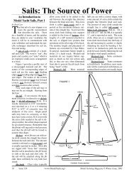
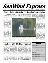
Figure 1 provides a pr<strong>of</strong>ile view <strong>of</strong><br />
a sloop-rigged mainsail and jib. <strong>The</strong><br />
names <strong>of</strong> the corresponding edges <strong>of</strong><br />
each sail are the same: luff (leading<br />
edge), leech (trailing edge) and foot (bottom<br />
edge). <strong>The</strong> names <strong>of</strong> the corners<br />
likewise correspond: head (top forward<br />
corner), tack (bottom forward corner)<br />
and clew (bottom after corner).<br />
Now, each edge <strong>of</strong> the sail may or<br />
may not be cut straight. Starting from<br />
the bow:<br />
Jib luff – if cut concave, the maximum<br />
concavity is referred to as jib hollow,<br />
or jib luff allowance (JLA). It is<br />
usually measured in 1/32” increments,<br />
and reported as a 4 or a 6 meaning<br />
4/32” or 6/32” <strong>of</strong> concavity near the<br />
midpoint <strong>of</strong> the curve. Single panel<br />
sails may have no concavity, or they<br />
may have some convex JLA to provide<br />
the extra cloth needed in the sail to develop<br />
camber, the airfoil shape required<br />
for good performance. Remember that<br />
the jibstay will sag under wind pressure<br />
and that the jib luff will be forced to<br />
assume that shape.<br />
Jib foot – most jibs are cut with extra<br />
cloth outside the straight line drawn<br />
between the tack and clew. <strong>The</strong> amount<br />
outside is referred to as foot round, and<br />
is usually reported in inches. Most jibs<br />
are rigged with “loose feet” meaning<br />
that the sail is attached to the jib boom<br />
or club at the tack and clew only. If<br />
the sail will be attached along the jib<br />
club, there will likely be very little foot<br />
round.<br />
Jib leech – Class rules typically<br />
allow extra cloth to be added to the<br />
sail between the straight line distance<br />
between the head and clew. This extra<br />
cloth is called leech roach and is reported<br />
as the maximum distance outside<br />
<strong>of</strong> the straight line. To prevent this<br />
extra cloth from folding over, support<br />
is added in the form <strong>of</strong> battens, short<br />
lengths <strong>of</strong> a stiff material attached to<br />
the sail, or slipped into pockets that<br />
terminate on the after edge <strong>of</strong> the leech.<br />
<strong>The</strong> number, length and placement <strong>of</strong><br />
battens are controlled by Class Rules.<br />
In general, maximum batten length is<br />
about 2.5 x leech roach. Modern sail<br />
materials do not require batten support<br />
as much as the old cotton sails<br />
did, so they are very <strong>of</strong>ten eliminated<br />
from jibs to prevent the jib leech from<br />
being “hard” or flat.<br />
Mainsail luff – Most mainsail<br />
TACK<br />
LUFF<br />
Luff Edge<br />
FIGURE 1<br />
Luff<br />
Allowance<br />
FOOT<br />
luffs are cut with a convex shape, with<br />
some amount <strong>of</strong> extra cloth outside the<br />
straight line between head and tack.<br />
<strong>The</strong> amount <strong>of</strong> extra cloth outside the<br />
straight line is called luff round, or<br />
Main Luff Allowance (MLA). On a<br />
sail with a 67” luff, the MLA is typically<br />
¼”, and is reported as such. <strong>The</strong> extra<br />
cloth, when set on a straight mast the<br />
extra cloth moves back into the body <strong>of</strong><br />
the sail increasing its camber or depth.<br />
Adjusting the mast by bending it forward<br />
in its midsections pulls the extra<br />
cloth forward, thereby flattening the sail<br />
for higher wind speed condition.<br />
Mainsail foot – Same comments<br />
apply as for the jib foot.<br />
Mainsail leech – Same comments<br />
as for jib leech. In addition, most mainsails<br />
will be constructed with battens, as<br />
mainsail leech roaches are usually larger<br />
18 Issue 130 <br />
<strong>Model</strong> <strong>Yachting</strong> Magazine © Winter Issue, 2003<br />
JIB<br />
Foot<br />
Round<br />
m<br />
HEAD<br />
CLEW<br />
D<br />
LEECH<br />
LUFF<br />
Leech<br />
Roach<br />
HEAD<br />
TACK<br />
Camber Cross-section<br />
L<br />
Luff<br />
Round<br />
MAIN<br />
FOOT<br />
Leech<br />
Roach<br />
LEECH<br />
Foot Round<br />
Leech Edge<br />
CLEW
than jib leech roaches. Care must be<br />
taken that the battens are not so stiff<br />
that they flatten the after third <strong>of</strong> the<br />
sail to look like a barn door. Battens on<br />
modern sails assist in shaping the after<br />
parts <strong>of</strong> the sail, the cloth is generally<br />
stable enough to hold itself fairly well,<br />
needing just a bit <strong>of</strong> help.<br />
Sail Shape<br />
Figure 1B shows a cross section <strong>of</strong><br />
a sail. <strong>The</strong> wind blows from right to<br />
left. <strong>The</strong> dimension “L” is the chord<br />
across the sail, a straight line from luff<br />
to leech. <strong>The</strong> % camber is found by dividing<br />
the maximum depth “D” by the<br />
chord “L”. <strong>Model</strong> yachts sails typically<br />
have cambers which vary from 5% for<br />
flat sails, to 15% for quite full sails. <strong>The</strong><br />
position <strong>of</strong> maximum draft is found by<br />
dividing “M” by “L”. Mainsails generally<br />
have maximum draft located at<br />
40% to 50% <strong>of</strong> chord, while jibs can be<br />
successful with maximum draft located<br />
at 35% to 40%. <strong>Sails</strong> with maximum<br />
draft forward have good acceleration,<br />
don’t point particularly well, and have<br />
a fairly low top speed potential, generally<br />
a good form for light winds. <strong>Sails</strong><br />
with maximum draft aft have good<br />
pointing ability, have a good top end<br />
<br />
<br />
speed capability and are recommended<br />
for medium to heavy winds. Draft<br />
stripes are <strong>of</strong>ten put on model yacht<br />
sails to assist in visualizing the shape in<br />
the sail when full <strong>of</strong> wind.<br />
Sail Construction<br />
<strong>Sails</strong> come in two general varieties<br />
<strong>of</strong> construction; single panel, where<br />
the entire sail is one piece <strong>of</strong> cloth without<br />
seams, gores, or cuts in the body <strong>of</strong><br />
the sail; and paneled, where each sail is<br />
made up <strong>of</strong> panels or strips <strong>of</strong> cloth, attached<br />
edge to edge with tapered seams<br />
to induce three dimensional shape in the<br />
sail when filled with wind.<br />
Single panel sails <strong>of</strong> a woven material<br />
are typically encountered in the<br />
construction <strong>of</strong> “kit” boats, because<br />
single panel sails are much less costly for<br />
the kit maker to provide. <strong>The</strong>y are also<br />
found in several AMYA racing classes,<br />
such as the CR 914 and Soling One<br />
Meter where the Class Rules require either<br />
kit sails only, or aftermarket single<br />
panel sails cut to a specific size. <strong>The</strong> details<br />
<strong>of</strong> successful set, trim and tuning<br />
<strong>of</strong> single panel sails is an entire subject<br />
in itself. Your sailmaker should be able<br />
to provide you with guidance if you are<br />
purchasing sails <strong>of</strong> this type from him.<br />
At the very least, he should inform you<br />
<strong>of</strong> the JLA and MLA measurements so<br />
that you will have a starting point for<br />
setting up your initial mast shape, and<br />
backstay tension. Single panel sails<br />
must be full <strong>of</strong> air, so that the cloth can<br />
stretch under the wind loading and can<br />
begin to take on the cambered shape<br />
necessary for drive.<br />
Paneled sails are used in the greater<br />
proportion <strong>of</strong> racing classes, and also<br />
in scale models that are going to be operated<br />
on the water. <strong>The</strong>y provide superior<br />
performance because the airfoil<br />
shape that produces drive for propelling<br />
the hull is built into the sail. Most<br />
use a membrane material such as a mylar<br />
sandwich with load carrying fibers,<br />
or mylar film. <strong>The</strong>se modern materials<br />
don’t stretch, so the cambered shape<br />
must be built into the sail with tapered<br />
seams that hold the panels together.<br />
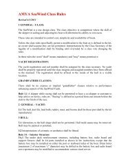
Sail Attachment<br />
A sail is attached to the spars by<br />
each <strong>of</strong> the three corners and by the<br />
luff <strong>of</strong> the sail to either the mast or<br />
the jibstay. (See Figure 2) In the case<br />
<strong>of</strong> the jib, almost all jib luffs are fitted<br />
with a hem into which the jibstay slides.<br />
This supports the sail along its length<br />
<strong>American</strong> <strong>Model</strong> <strong>Yachting</strong> <strong>Association</strong> © 2003 <br />
Issue 130 19
Down<br />
Haul<br />
TACK<br />
Jibstay<br />
Halyard<br />
(fixed)<br />
and makes for a smooth and clean entry<br />
where the wind meets the sail. <strong>The</strong><br />
luff hem method eliminates scalloping<br />
which can happen with the tubes, and<br />
it distributes the wind load evenly over<br />
the entire luff. Some jibs are mounted<br />
using little hollow tubes affixed to the<br />
sail that are slid over the jibstay. <strong>The</strong><br />
sail tubes provide for excellent swiveling<br />
as the sail tacks, but produce point<br />
loads where they attach to the sail, and<br />
this can cause the sail to wear out prematurely.<br />
<strong>The</strong> head <strong>of</strong> the jib usually contains<br />
a grommet to which is attached<br />
a halyard. For ease <strong>of</strong> adjustment, the<br />
halyard is fixed, usually up at the jibstay<br />
attachment point. Tension is adjusted<br />
on the sail luff by use <strong>of</strong> a downhaul,<br />
which is tied to the tack grommet, led<br />
to the jib club, and back about half way<br />
down the club to some sort <strong>of</strong> a tension<br />
adjustment like a cleat, 3-hole bowsie,<br />
HEAD<br />
Mast<br />
CLEW<br />
Jib Club Jib Club<br />
Figure 2<br />
Sail Corner Rigging<br />
or other device. <strong>The</strong> clew is constrained<br />
in the vertical direction by something<br />
as simple as a loop <strong>of</strong> sheet line tied<br />
through the clew grommet and led under<br />
and around the club. A second line,<br />
called the clew outhaul, leads aft to the<br />
end <strong>of</strong> the jib club, and provides for adjusting<br />
the position <strong>of</strong> the clew along<br />
the club, controlling the fullness <strong>of</strong> the<br />
foot and the bottom third <strong>of</strong> the jib.<br />
<strong>The</strong> corners <strong>of</strong> the mainsail are<br />
rigged in the same way.<br />
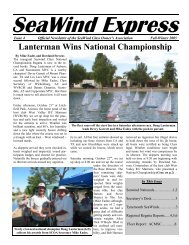
<strong>The</strong> luff <strong>of</strong> the mainsail must<br />
be mated with the mast, and many<br />
methods have been developed over the<br />
years. <strong>The</strong> mast material drives part <strong>of</strong><br />
the solution, while the size <strong>of</strong> the boat<br />
and/or the class rules under which the<br />
boat will sail may provide other opportunities<br />
or constraints. Figure 3 shows<br />
a series <strong>of</strong> approaches to this problem,<br />
certainly not exhaustive by any means.<br />
Smaller classes, such as the 36/600, Vic-<br />
toria, Fairwind, International One Meter<br />
and U.S. One Meter, that use round<br />
mast materials like aluminum or carbon<br />
fiber tube, use the mast loop method<br />
(3A) with good success. Aerodynamically<br />
it provides the best leading edge,<br />
which gets traded <strong>of</strong>f against a shorter<br />
sail lifetime since the luff is attached<br />
at discrete points. Jackwire methods<br />
(3B) work well, with various methods<br />
employed for holding the wire to the<br />
mast. We show a row <strong>of</strong> cotter pins set<br />
through the mast, with “windows” cut<br />
in the sail for clearance. Dress hooks<br />
have been used for attachment to the<br />
jackwire, but seem typical <strong>of</strong> only vintage<br />
boats these days. Extruded masts<br />
like the Bantock “Groovey” and the<br />
Ozmun “Goldspar” are amenable to<br />
the standard bolt-rope (3C). This<br />
method produces generally poor sail<br />
shape at the exit to the mast slot, and<br />
poor hinging ability in light air. Jackwire<br />
methods using mast slides or other<br />
attachment methods (3D) produce<br />
better hinging and longer sail lifetimes.<br />
Mast slugs or beads directly attached<br />
to reinforcement patches on the luff<br />
are also used (3E).<br />
Sail Setting Assessment<br />
Success in sail setting requires an<br />
understanding <strong>of</strong> the match between<br />
the flexible sail and its mounting component.<br />
For mainsails, the mast shape<br />
must be matched to the shape <strong>of</strong> the<br />
mainsail luff for a good match. For jibs,<br />
the jib luff shape needs to be cut so that<br />
it harmonizes with the sag in the jibstay<br />
which results from wind pressure on the<br />
sail.<br />
If your sailmaker doesn’t tell you<br />
your jib luff allowance, you must measure<br />
it. Tape the leading edge <strong>of</strong> the<br />
sail at the head and tack to a flat surface.<br />
Make a clew holder by drilling a<br />
bunch <strong>of</strong> holes in an 18” long piece <strong>of</strong><br />
2x2 screwed to a plywood base which<br />
can be weighted, then put a 4” piece<br />
<strong>of</strong> pointed stiff wire in the appropriate<br />
hole to hold the clew. Elevate the clew<br />
<strong>of</strong> the sail until the sail swoops down<br />
toward the luff and becomes just tangent<br />
where the luff hits the table. Adjust<br />
the position <strong>of</strong> the clew holder by<br />
moving it parallel to the luff to adjust<br />
for twist in the sail. Moving the holder<br />
toward the head will allow the upper<br />
leech to sag and twist <strong>of</strong>f. A small<br />
amount <strong>of</strong> twist should exist in the sail.<br />
Photo 1 shows a jib which has been set<br />
20 Issue 130 <br />
<strong>Model</strong> <strong>Yachting</strong> Magazine © Winter Issue, 2003
Mast Loops<br />
Cotter pin /<br />
Jackwire<br />
up like this. Use a straight edge between<br />
the head and tack and measure<br />
the distance to the luff in 32nds <strong>of</strong> an<br />
inch, this is the JLA for that sail.<br />
You now know how much the jibstay<br />
must sag to exactly match the shape<br />
cut in the luff <strong>of</strong> the sail. <strong>The</strong> higher the<br />
wind blows, the more sag will occur. So<br />
in general, model yacht sails are cut with<br />
somewhere between 4/32” and 10/32” <strong>of</strong><br />
JLA. <strong>The</strong> amount depends on the target<br />
wind range and on the length <strong>of</strong> the<br />
luff itself.<br />
While the jib is standing there, observe<br />
it for its general characteristics.<br />
Where is the point <strong>of</strong> maximum draft?<br />
Is the leading half <strong>of</strong> the sail smooth and<br />
gently rounded? A few pictures taken<br />
with a digital camera can be printed out<br />
in black and white and measurements<br />
Bolt-rope<br />
Figure 3: Mast Sail Attachment Methods<br />
Jackwire<br />
Bolt-rope Jackwire Bead/Tube<br />
made which allow camber, maximum<br />
draft, entry angle and so on to be calculated.<br />
<strong>The</strong> shape the sail shows here is<br />
caused by gravity, not wind. <strong>The</strong> weight<br />
<strong>of</strong> the typical sail (1.0 oz/sq yd) can be<br />
equated to a wind pressure from a 1 to<br />
1.5 mph wind. So one should expect<br />
some changes in shape once the sail is<br />
on the boat on the water.<br />
Mainsails are also amenable to inspection<br />
by the same method. MLA<br />
must be determined for the luff <strong>of</strong> the<br />
mainsail so that a proper mast shape can<br />
be matched to the shape <strong>of</strong> the mainsail<br />
luff. Photo 2 shows a sail with the head<br />
and tack taped down, and clew elevated.<br />
<strong>The</strong> straight edge along the luff allowed<br />
measurement <strong>of</strong> 3/32” <strong>of</strong> luff hollow to<br />
be determined. This means that a mast<br />
match for this sail requires for the cen-<br />
Photo 1: Finding the jib luff allowance. Photo 2: Main luff measurement.<br />
distance not to scale<br />
ter <strong>of</strong> the mast to be pulled aft by 3/32”.<br />
As wind speed increases, masts usually<br />
bow forward under increased backstay<br />
tension. This sail will not respond well<br />
to that change in mast shape, so is likely<br />
intended for use in only the lightest<br />
<strong>of</strong> airs. We observe that this is a very<br />
“draft-forward” sail, so good for acceleration,<br />
but with a low top speed capability.<br />
Pointing and top speed are not<br />
so important in light air, where acceleration<br />
after tacks and mark roundings is<br />
critical to racing performance. Notice<br />
that the leech area is very flat, caused by<br />
extremely stiff battens.<br />
Initial Close Hauled Tuning<br />
With the sails on the boat, and the<br />
boat on its side so that you can sight<br />
down the mast, the following are good<br />
starting points for tuning your new sails<br />
for windward performance in light air.<br />
1) Mast shape should be straight<br />
for-and-aft. This allows mainsail luff<br />
round to give added fullness to the<br />
mainsail.<br />
2) Set mainsail sheet so that bottom<br />
batten <strong>of</strong> mainsail is parallel to the<br />
main boom.<br />
3) Set main boom vang so that<br />
sail twists <strong>of</strong>f al<strong>of</strong>t until top batten is<br />
parallel to the main boom.<br />
4) Adjust jib sheet so that jib<br />
boom points just inboard <strong>of</strong> the side<br />
shroud chain plate.<br />
5) Adjust topping lift so that jib<br />
twist, when the jib leech is viewed from<br />
aft matches the twist set in the mainsail.<br />
Now you are ready to begin a reiterative<br />
process searching for optimum<br />
performance. Put the boat on the water,<br />
check for boat balance. If too much<br />
weather helm, the rig may need to be<br />
moved forward. If only a little weather<br />
helm, you may need to trim the jib<br />
in slightly. Sailing with a partner who<br />
doesn’t make a change while you do will<br />
give you a benchmark against which<br />
you can gauge improvement.<br />
Further information on tuning<br />
can be found in Tuning Guides that<br />
some model yacht sailmakers include<br />
with their products. You can also<br />
delve into books written for people<br />
who sail boats that they insist in sitting<br />
in! A couple good references<br />
are: SAIL POWER by Wallace Ross,<br />
(1975) ISBN 0-394-47151-2; and SAIL<br />
PERFORMANCE by C.A.Marchaj,<br />
(1990) ISBN 0-07-040250-7.<br />
<strong>American</strong> <strong>Model</strong> <strong>Yachting</strong> <strong>Association</strong> © 2003 <br />
Issue 130 21<br />
distance not to scale<br />
Tape Reinforcement