Santa Barbara and 36/600 - American Model Yachting Association
Santa Barbara and 36/600 - American Model Yachting Association
Santa Barbara and 36/600 - American Model Yachting Association

You also want an ePaper? Increase the reach of your titles
YUMPU automatically turns print PDFs into web optimized ePapers that Google loves.
A Quarterly Publication of the <strong>American</strong> <strong>Model</strong> <strong>Yachting</strong> <strong>Association</strong>, Spring 2007, Issue Number 147 US$7.00<br />
Featuring<br />
<strong>Santa</strong> <strong>Barbara</strong><br />
<strong>and</strong><br />
<strong>36</strong>/<strong>600</strong>
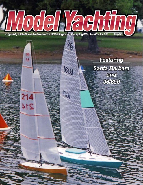
On the Cover<br />
Photo by Dennis Deprois. This picture was taken at the<br />
Mission Bay <strong>Model</strong> Yacht Pond in San Diego, California,<br />
during Race Week 2006, sponsored by the San Diego Argonauts.<br />
It was the first day of the National Championship Regattas<br />
for the <strong>Santa</strong> <strong>Barbara</strong> <strong>and</strong> <strong>36</strong>/<strong>600</strong> Classes. The picture<br />
was taken just before the first race. The <strong>36</strong>/<strong>600</strong>, sail #214, is<br />
being sailed by Craig Macky of Bellevue, Washington. Craig<br />
sailed on to the 2006 <strong>36</strong>/<strong>600</strong> National Championship. He is<br />
racing a Venom made by Bob Stern, who has written an article<br />
for this issue. The <strong>Santa</strong> <strong>Barbara</strong>, sail #1601, is being<br />
sailed by Ken Forbes of Escondido, California. He is sailing a<br />
new boat manufactured by Ludwig Mfg. of University City,<br />
Texas. The boat was built by Bob DeBow of San Diego.<br />
The <strong>American</strong> <strong>Model</strong> <strong>Yachting</strong> <strong>Association</strong> (AMYA), a not-forprofit<br />
organization that is dedicated to promoting the designing, building,<br />
racing, <strong>and</strong> preservation of all model sailing yachts <strong>and</strong> is open to all<br />
people who are interested in these activities..<br />
In pursuit of these goals, the AMYA publishes <strong>Model</strong> <strong>Yachting</strong> Magazine.<br />
<strong>Model</strong> <strong>Yachting</strong> is published four times per year in accordance with<br />
the AMYA calendar. The staff of the magazine is composed primarily of<br />
AMYA member volunteers who devote countless hours of their time to<br />
produce this publication. Editorial policy is ultimately determined by the<br />
AMYA Board of Directors; however, the views expressed in this publication<br />
do not necessarily represent the views of the Executive Board, the<br />
Board of Directors, or the majority of the AMYA membership.<br />
Advertising in this publication is encouraged as an informative service<br />
to the AMYA members <strong>and</strong> as a means of helping defray the costs of<br />
printing. The AMYA does not take any responsibility for any advertiser’s<br />
products.<br />
This issue of <strong>Model</strong> <strong>Yachting</strong>, except those parts as are specifically<br />
stated, is Copyright © 2007 by the <strong>American</strong> <strong>Model</strong> <strong>Yachting</strong> <strong>Association</strong>,<br />
January 2007. All rights reserved.<br />
Advertiser Index<br />
<strong>American</strong> RC 52<br />
Anchor Bay Specialties 46<br />
Black Sails 24<br />
Bob’s BoatYard 26<br />
Carr Sails 19<br />
Chesapeake Performance <strong>Model</strong>s 48<br />
Dennis Desprois’ Walrus Sails 26<br />
GBMY—Great Basin <strong>Model</strong> Yachts 40<br />
GRP <strong>Model</strong> Yachts 2<br />
Hanna Boats 68<br />
Hitec 19<br />
<strong>Model</strong> Yacht Fittings 58<br />
R/C Concepts 50<br />
RMD Marine 45<br />
RMG Sailwinch 19<br />
Scale Sailing 57<br />
The Boat Shop 46<br />
Traplet Distribution USA Ltd 67<br />
US 12 <strong>and</strong> Liberty 34 54<br />
Victor <strong>Model</strong> Products 44<br />
Vision Sails 47<br />
Contents of Issue 147<br />
The Masthead ...........................................................4<br />
President’s Letter ......................................................5<br />
<strong>Model</strong> <strong>Yachting</strong> News ................................................6<br />
AMYA Business Calendar ........................................6<br />
The <strong>Santa</strong> <strong>Barbara</strong> Class ..........................................7<br />
Assembling a <strong>Santa</strong> <strong>Barbara</strong>, Part 1..........................9<br />
Epoxy Construction Pointers ..................................20<br />
Cartoon by Ralph Kanko .......................................21<br />
Tote that Boat .........................................................22<br />
The Helmsmen <strong>Model</strong> Yacht Club ..........................23<br />
Race Yourself Against the Clock ............................24<br />
The <strong>36</strong>/<strong>600</strong> Class .....................................................25<br />
The Venom <strong>36</strong>/<strong>600</strong> ..................................................27<br />
Let’s Race With The Rules, Rules Tutorial, Part 4 ...28<br />
Regatta Reports ......................................................32<br />
Regatta Schedule ....................................................43<br />
Class News & Views ................................................44<br />
Soling One Meter ..............................................44<br />
East Coast 12 Meter ..........................................45<br />
Victoria .............................................................45<br />
US One Meter ...................................................46<br />
Marblehead .......................................................47<br />
CR 914 ..............................................................48<br />
<strong>36</strong>/<strong>600</strong> ................................................................49<br />
Star 45 ...............................................................49<br />
V-32 ...................................................................50<br />
<strong>Santa</strong> <strong>Barbara</strong> ...................................................51<br />
SeaWind ............................................................51<br />
Soling 50 ...........................................................52<br />
Open .................................................................52<br />
RC Laser ...........................................................53<br />
US12 .................................................................54<br />
AC .....................................................................55<br />
Newport 12 Meter .............................................56<br />
J ........................................................................57<br />
Footy .................................................................57<br />
10 Rater .............................................................58<br />
Wheeler .............................................................59<br />
Infinity 54 ..........................................................59<br />
The US Vintage <strong>Model</strong> Yacht Group ................59<br />
2007 Vintage M 50-800 Championship ...................60<br />
A Tribute to Bill Bithell...........................................61<br />
AMYA Stats & Facts ..............................................62<br />
AMYA Treasurers Report .......................................63<br />
AMYA Executive Secretary Report-The 2007 Election ..64<br />
Cut-out Correction for Issue 146 ............................64<br />
AMYA Yacht Registration Form ............................64<br />
AMYA Ship’s Store Order Form.............................65<br />
AMYA Membership Form .....................................66<br />
Issue 148 Final Deadline is March 26, 2007<br />
Featuring<br />
The Soling One Meter Class<br />
<strong>American</strong> <strong>Model</strong> <strong>Yachting</strong> <strong>Association</strong> © 2007 <br />
Issue 147 3
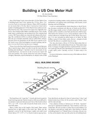
Assembling a <strong>Santa</strong> <strong>Barbara</strong><br />
Part 1<br />
By Rich Matt<br />
Have you<br />
considered a<br />
<strong>Santa</strong> <strong>Barbara</strong><br />
One Design (S/B OD)?<br />
To find out more about<br />
the boat, ask a person<br />
already owning one, <strong>and</strong><br />
he will most likely start<br />
out by telling you, “It’s a<br />
good performing boat.”<br />
He will go on to compare<br />
the looks, sailing characteristics,<br />
<strong>and</strong> h<strong>and</strong>ling<br />
of the S/B to that of a<br />
full-size racing sailboat.<br />
Experienced sailors will<br />
also be ready to tell you<br />
that the S/B class rules<br />
provide a certain appeal<br />
to those who prefer to<br />
sail rather than argue.<br />
The hulls <strong>and</strong> keels are<br />
as alike as cupcakes. A<br />
single one-size rig having one sail plan is<br />
specified—No need for a Storm Rig, A,<br />
B, C, or even a D rig! Only user-friendly<br />
lead shot pellets are allowed as keel ballast.<br />
A couple inches shorter than six feet<br />
long, having a tall 72” sail rig, a 16 lb fin<br />
keel, <strong>and</strong> a balanced rudder means it will<br />
sail a steady coarse, be highly maneuverable<br />
at a starting line, <strong>and</strong> be big enough<br />
to be seen when rounding a mark. A<br />
sturdy, seaworthy deck is required. Both<br />
a minimum-maximum keel weight <strong>and</strong><br />
an all-up weight requirement are specified.<br />
In 1970, the S/B OD was the very<br />
first to get Sanctioned Class status by the<br />
AMYA, <strong>and</strong> thirty-six years later, it is still<br />
around <strong>and</strong> going strong! Not too many<br />
boats can match all these advantages.<br />
The one-design concept of the S/B<br />
has been maintained successfully ever<br />
since Tom Protheroe designed it way<br />
back in 1968. Older boats fitted with<br />
modern sails routinely demonstrate they<br />
are just as fast <strong>and</strong> competitive as newer<br />
ones. A used S/B, up for sale, will probably<br />
bring the same price as when the<br />
seller first bought it. It has proven to be<br />
large enough, heavy enough, <strong>and</strong> sturdy<br />
enough to h<strong>and</strong>le strong winds <strong>and</strong> large<br />
waves. Yet, for its size, it is not all that difficult<br />
to pack up <strong>and</strong> transport. Pondside<br />
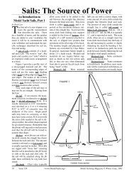
The <strong>Santa</strong> <strong>Barbara</strong> One Design is a legend in the world of R/C sailing. These S/Bs are heading for the weather<br />
mark in San Diego where the Argonauts have hosted regattas for the class since 1971. Photo by Bruce Lopez.<br />
assembly or disassembly of the rig, rudder,<br />
<strong>and</strong> keel takes only a few minutes.<br />
When Vortex <strong>Model</strong> Engineering<br />
stopped producing, the S/B the class<br />
went for over a decade without a source<br />
of new boats. Then, about ten years ago,<br />
Dwight Hartman’s Hartman R/C Fibreglass<br />
came to the rescue <strong>and</strong> started making<br />
available the Yacht 420 hulls, keels,<br />
decks, <strong>and</strong> rudders. No longer did the<br />
class need to sustain itself on the availability<br />
of used boats alone. Once again,<br />
folks having a basic workbench <strong>and</strong> kitbuilding<br />
skills were able to put together a<br />
new boat meeting the class specifications.<br />
Dwight Hartman has a long-st<strong>and</strong>ing<br />
reputation for supplying quality products.<br />
For example, more than 900 of his<br />
42” LOA (length overall) Douglas Greg<br />
Harbor Tug kits have been produced.<br />
Today, in addition to Hartman R/<br />
C Fibreglass, there are two more S/B<br />
Class-approved manufacturers: Ludwig<br />
Mfg. Co. <strong>and</strong> Midlife Boats. If you are<br />
ready for a S/B Class boat of your own,<br />
you now have options. With three S/B<br />
OD class-approved manufacturers to<br />
pick from, you can find a boat in do-ityourself<br />
kit form or pre-assembled to<br />
any degree of completion. Whether a<br />
short kit having the molded parts alone<br />
or a boat completely assembled, it is like<br />
ordering a pizza. Decide on your extra<br />
toppings <strong>and</strong> baking style when you<br />
place your order. Also, as when ordering<br />
a pizza, you might need to wait in line<br />
for your order <strong>and</strong> wait for your order<br />
to bake—our S/B Class suppliers do not<br />
necessarily have their products in inventory<br />
<strong>and</strong> ready for immediate delivery.<br />
Supplier Option 1: From Hartman<br />
R/C Fibreglass, Box 86, 233 Melrose<br />
St., Argenta, IL 62501; or phone: 7:00<br />
to 9:00 a.m. or p.m. CST, 217-795-2275.<br />
Order Yacht 420 hull—$154.00, keel—<br />
$95.00, keel installation pack—$5.00,<br />
rudder—$15.00, Soling-50-style deck<br />
with hatch covers—$104.00, full-size<br />
plans—$10.00, <strong>and</strong> a double-wall cardboard<br />
shipping box—$10.00. It adds up<br />
to about $400.00. The epoxy-resin fiberglass<br />
parts require some trimming, some<br />
filling, <strong>and</strong> painting. Dwight Hartman<br />
offers only the essential fiberglass parts.<br />
He does not offer wooden parts, leadshot<br />
keel ballast, spars, hardware, or<br />
sails. The kit builder has other sources<br />
<strong>and</strong> choices for those items. The Hartman<br />
S/B Short Kit in the h<strong>and</strong>s of a kit<br />
builder having average skills will result<br />
in a nice boat, which has been proven to<br />
win races <strong>and</strong> will hold its value.<br />
<strong>American</strong> <strong>Model</strong> <strong>Yachting</strong> <strong>Association</strong> © 2007 <br />
Issue 147 9
This S/B OD was assembled using the<br />
Short Kit parts available from Hartman<br />
R/C Fibreglass. Photo by Rich Matt<br />
Dwight Hartman in his workshop. The<br />
mold alongside is for an EC12. He is<br />
a Class-Approved Manufacturer of the<br />
S/B OD, EC12, <strong>and</strong> Soling 50. Photo<br />
by Rich Matt<br />
Supplier Option 2: Ludwig Manufacturing<br />
Co., 429 E. Wright Blvd.,<br />
Universal City, TX 78148. Phone:<br />
210-724-3827. Website: .<br />
E-mail: . Larry Ludwig<br />
offers the <strong>Santa</strong>na 70, a class-approved<br />
hull, ocean-racer style deck, rudder, <strong>and</strong><br />
ballasted keel, all in white gelcoat for<br />
$415.00. Larry is available to install the<br />
necessary interior parts <strong>and</strong> assemble the<br />
short kit. Rather than use wood for below-deck<br />
support parts, if he is doing the<br />
assembly, he prefers the use of Divinycell<br />
foam-core glass s<strong>and</strong>wich. For him to<br />
install the deck reinforcing parts, install<br />
the keel supports, install the rudderpost,<br />
<strong>and</strong> install the deck, it will cost about<br />
an additional $200.00. He is available to<br />
also assemble, equip, <strong>and</strong> rig the boat,<br />
ready for the water—whatever degree of<br />
completion a buyer might want. Hardware<br />
available from Ludwig Mfg. Co. includes<br />
an airfoil shaped, clear-anodized,<br />
T-6 6061 aluminum 72” mast plus 24”<br />
main boom for $27.00. Other new hardware<br />
items include: a mast crane, mast<br />
deck step, gooseneck, boom vang swivel,<br />
clew slide, <strong>and</strong> spreaders, all of which are<br />
made from carbon, stainless steel, plastic,<br />
or nickel-plated brass, which is rustfree<br />
<strong>and</strong> useable in salt water.<br />
A S/B OD like this one is available from<br />
Ludwig Mfg. as a Short Kit or pre-assembled<br />
to any degree of completion.<br />
Photo by Ernie Mortensen.<br />
Larry is holding together a fresh-fromthe-mold,<br />
Ocean Racer-style deck,<br />
along with a fresh-from-the-mold S/B<br />
hull. Photo by Rich Matt.<br />
Supplier Option 3: No short kit,<br />
but a gelcoated, assembled hull, deck,<br />
rudder, <strong>and</strong> ballasted keel that meets<br />
the class rules; the Ventura 70, is available<br />
from Midlife Boats, 5264 N. Ventura<br />
Ave., Ventura, CA 93001. Website:<br />
. E-mail: <br />
to contact Mi-<br />
chael Kelley, or to contact Ron Thornhill. Phone:<br />
805-658-1108. This fully assembled <strong>and</strong><br />
ballasted boat, ready for you to install<br />
your radio, winch, deck hardware, <strong>and</strong><br />
sail, is available for $800.00. Or, you can<br />
opt for them to provide the boat fully<br />
rigged <strong>and</strong> ready for the water.<br />
Ron Thornhill (top photo) <strong>and</strong> Mike<br />
Kelley (bottom photo) are proprietors<br />
of Midlife Boats. Their S/B class approved<br />
boat comes from the shop with<br />
the deck attached to the hull. Top photo<br />
by Mike Kelley. Bottom photo by Ron<br />
Thornhill.<br />
Option 4: Visit <br />
<strong>and</strong> check out Honest<br />
Ahab’s Classified For-Sail Ads. Mark<br />
Cooper does a great job of managing<br />
the classified ads for Ahab’s web page.<br />
Another source of used boats is the new<br />
<strong>Santa</strong> <strong>Barbara</strong> Class Internet forum:<br />
A S/B like this one is available from<br />
Midlife Boats, completely assembled<br />
<strong>and</strong> ready for the water. Photo by<br />
Mike Kelley.<br />
ta<strong>Barbara</strong>OD>. Occasionally, a <strong>Santa</strong><br />
<strong>Barbara</strong> is listed for sale on Ebay. Notice<br />
how a twenty- or thirty-year-old S/<br />
B holds its value! If needed, a new suit<br />
of sails <strong>and</strong> some rigging maintenance<br />
are all it might take to revive an older<br />
boat to race-winning condition.<br />
Also to be considered in addition to<br />
the hull, keel, rudder, <strong>and</strong> deck are those<br />
things that are essential to every R/C<br />
sailboat: sails, a device for trimming the<br />
sails, spars, rigging, <strong>and</strong> hardware. At<br />
least a two-channel radio will be needed<br />
for operating sheets <strong>and</strong> rudder. The<br />
class does not limit the number of channels<br />
<strong>and</strong> servo functions. Many S/Bs are<br />
also equipped with jib trim, adjustable<br />
backstay, <strong>and</strong> jib flipper.<br />
Since the S/B is a big boat having a<br />
big sail rig <strong>and</strong> is often sailed in strong<br />
winds, the Sail Control Unit (SCU)<br />
needs to have some muscle. The most<br />
popular S/B SCU is of the swingingarm<br />
variety. This type of sail control can<br />
be mounted to one side of the keel-bolt<br />
wing nuts <strong>and</strong> works a single, long arm,<br />
or it can be mounted on the centerline<br />
between the keel-bolt wing nuts if having<br />
a two-sided arm. A good one to<br />
consider is the W-12 SCU from Ozmun<br />
Design, <strong>36</strong>08 Fox Road, Huron, OH<br />
44839. Phone: 419-433-3025. The W-12<br />
sells for $160.00 plus $7.00 shipping <strong>and</strong><br />
h<strong>and</strong>ling (s&h). Ray Ozmun now makes<br />
available another version of the winch,<br />
the W-12BB. It features stainless steel<br />
ball bearings, output shaft, <strong>and</strong> other<br />
parts. The basic W-12 is a stump puller<br />
to begin with, but with these modifications,<br />
it results in an additional 100 lbinch<br />
of torque. The W-12BB sells for<br />
$250.00 plus $7.00 s&h. For a long time,<br />
Ozmun Design has provided the popular<br />
Goldspar airfoil-shaped aluminum<br />
masts <strong>and</strong> booms. The 72” mast costs<br />
$25.00 plus $7.00 for the mailing tube.<br />
For $9.00 additional, you can get a 24”<br />
main boom made of the same aluminum<br />
mast material. Since the boom can<br />
be readily inserted in the shipping tube<br />
along with the mast, there is no additional<br />
shipping <strong>and</strong> h<strong>and</strong>ling expense.<br />
If you would rather install a<br />
drum-style winch, consider the RMG<br />
SmartWinch. It is high speed, high<br />
torque, <strong>and</strong> “intelligent.” RMG, has a display<br />
ad here in <strong>Model</strong> <strong>Yachting</strong>. Some<br />
of the S/Bs in California are using the<br />
RobotZone SPG815 servo with the 4:1<br />
ratio as a swinging arm SCU; for more<br />
info: .<br />
You will need a suit of sails made<br />
according to the class rules. Black Sails,<br />
Carr Sails, <strong>and</strong> Bob’s Boat Yard have<br />
been in the business of making S/B sails<br />
for over three decades. Walrus Sails <strong>and</strong><br />
Vision Sails should also be considered.<br />
All five sail makers have display ads in<br />
this issue of <strong>Model</strong> <strong>Yachting</strong>. A virtue of<br />
the S/B OD Class is that one sail rig is all<br />
that is allowed <strong>and</strong> needed. In all winds,<br />
the boat moves well, stays in balance,<br />
<strong>and</strong> doesn’t submarine under this welldesigned,<br />
original sail plan.<br />
As mentioned above, an aluminum,<br />
foil-shaped mast in the S/B Class-required<br />
72” length is available from either<br />
Ludwig Mfg. Co. or Ozmun Design.<br />
Another version of aluminum mast <strong>and</strong><br />
a full-line of hardware are available from<br />
Great Basin <strong>Model</strong> <strong>Yachting</strong>: . If you prefer a carbon-fiber<br />
mast, contact Bob’s Boatyard, . Booms can be<br />
aluminum, carbon fiber, fiberglass arrow-shaft,<br />
or wood.<br />
A choice of hardware fittings is now<br />
available. Every boat needs a gooseneck,<br />
vang fittings, cleats, tangs, turnbuckles,<br />
chainplates, screws, screw eyes, bowsies,<br />
spreaders, rigging wire, jumper-stay fitting,<br />
<strong>and</strong> masthead fitting. Going to the<br />
Internet, or getting the neighbor’s computer-savvy<br />
kid to go to the Internet for<br />
you, is important when researching what<br />
model sailboat hardware is available.<br />
Start with Ludwig Mfg. Co. <br />
<strong>and</strong> other <strong>Model</strong><br />
<strong>Yachting</strong> advertisers: GRP <strong>Model</strong> Yachts<br />
, Great Basin<br />
<strong>Model</strong> <strong>Yachting</strong> (GBMY) , <strong>and</strong> Roger Cousineau<br />
.<br />
Also, while researching hardware<br />
on the Internet, be sure to go to AMYA<br />
Website, , bring<br />
up the Class Rules page, <strong>and</strong> print out<br />
the S/B Class Measurement Specifications.<br />
Every class of boat has measurement<br />
rules, which are intended to define<br />
the physical parameters <strong>and</strong> insure the<br />
boats are equally competitive with each<br />
other. For the <strong>Santa</strong> <strong>Barbara</strong>, the class<br />
rules are easy enough to deal with. In<br />
brief, all you need do is: 1) buy the hull<br />
<strong>and</strong> keel from a class-approved manufacturer;<br />
2) have a suit of sails that meet the<br />
measurement rule; 3) use cold lead shot<br />
<strong>and</strong> not poured molten lead as ballast<br />
<strong>and</strong> keep the keel between 13.5 <strong>and</strong> 16.5<br />
pounds; 4) use the same rudder as does<br />
everyone else; 5) install a seaworthy, hard<br />
material as decking; <strong>and</strong> 6) pay heed to<br />
a few measurement specifications: 1.62”<br />
maximum deck crown, 72” maximum<br />
mast height, 53.5” maximum jib stay<br />
attachment height, a beam tolerance of<br />
12.5” to 13.0” at 37” aft of the bow, <strong>and</strong> a<br />
full-boat weight of 23 to 28 pounds.<br />
When assembling a short kit, it will<br />
be necessary to get a variety of items<br />
from a hardware store or home-improvement<br />
big box. The wooden parts<br />
are made from an 8’ length of 1/4” x 1-<br />
3/8” pine lattice molding. Sheer strips<br />
for providing support <strong>and</strong> a gluing surface<br />
for the joint where hull meets deck<br />
can be made from a 6’ length of 1/4”<br />
by 1-3/8” pine lattice molding that has<br />
been rip-cut lengthwise. A 3’ length of<br />
5/8” diameter birch dowel, cut in half,<br />
installed under the deck to either side<br />
of the hatch opening makes for h<strong>and</strong>y<br />
boat carrying h<strong>and</strong>les. When it comes<br />
time to epoxy the deck to the hull, you<br />
will want a roll of duct tape <strong>and</strong> a roll<br />
of blue masking tape. Coarse, medium,<br />
<strong>and</strong> fine grit s<strong>and</strong>paper will be needed.<br />
A dozen “acid brushes” are essential<br />
for applying epoxy glue. A pint of acetone<br />
will help clean off mold release<br />
wax from gluing surfaces <strong>and</strong> clean epoxy<br />
from the acid brushes.<br />
Putting together a short kit means<br />
you also need to plan a trip to the hob-<br />
<strong>American</strong> <strong>Model</strong> <strong>Yachting</strong> <strong>Association</strong> © 2007 <br />
Issue 147 11
y shop. You will need an aircraft nylon<br />
steering arm for use on the rudder shaft,<br />
a package of nylon reinforcing tape for<br />
reinforcing wood-to-fiberglass glue<br />
joints, a fiberglass arrow shaft <strong>and</strong> clevis<br />
fittings to use as a rudder pushrod, both<br />
quick-set (5 or 15-minute) <strong>and</strong> slow-set<br />
(at least one-hour) epoxy glue (in that<br />
quick-set epoxies are not proven to be<br />
waterproof, a coating of slow-set epoxy,<br />
to be used later in the building process,<br />
is recommended to cover this vulnerability),<br />
a container of micro-balloon<br />
filler to thicken epoxy glue, a 6” x 12”<br />
sheet of 1/8” birch plywood to use as<br />
radio <strong>and</strong> SCU mounting boards, a jar<br />
of model maker’s surfacing putty, <strong>and</strong> a<br />
small bottle of thin CA glue for making<br />
lashings <strong>and</strong> knots permanent.<br />
The Ludwig Short Kit comes with<br />
a ballasted keel. But, if you are planning<br />
to get the Hartman R/C Fibreglass<br />
Short Kit, you will need to visit a firearms<br />
dealer for a bag of #8 lead shot<br />
to use as keel ballast. A half-pint can of<br />
polyester resin from the hobby shop will<br />
be needed in order to solidify the shot<br />
in the keel. For obvious reasons, a small<br />
funnel is essential to the keel ballasting<br />
procedure! If it happens that your local<br />
firearms dealer won’t sell you lead shot<br />
without you having a gun-owner registration<br />
permit, take this magazine over<br />
to the police department, show somebody<br />
this article, <strong>and</strong> ask them nicely to<br />
phone an Okay to the firearms dealer.<br />
You are not done chasing around<br />
just yet! Head on over to the fishing<br />
tackle store <strong>and</strong> pick up a spool of 45 lbtest<br />
Dacron line to use as sheets <strong>and</strong> for<br />
lashing the carrying h<strong>and</strong>les to the deck<br />
thwarts. While there, pick out a package<br />
of larger-size, ball bearing swivel clips to<br />
use as jib tack <strong>and</strong> backstay fittings.<br />
Opting to put together a fiberglassparts-only<br />
Short Kit from either Hartman<br />
or Ludwig means that you will<br />
need to provide the necessary wooden<br />
parts for supporting the removable rudder,<br />
removable keel, <strong>and</strong> permanent<br />
deck. Once you have gathered the pine<br />
lattice molding, birch dowel, <strong>and</strong> birch<br />
plywood, it will be necessary to roughcut<br />
the wood along its length, as well as<br />
cutting it to length. A table-saw is best;<br />
a motorized scroll saw will do nicely, or<br />
a fine-tooth h<strong>and</strong> saw would even work<br />
when doing the along-the-length “rip”<br />
cuts. Final fitting <strong>and</strong> tapering of each<br />
part is best done with a hobby razor saw<br />
<strong>and</strong> a s<strong>and</strong>ing block. Yes, it is possible<br />
<strong>and</strong> permitted to use a high-tech, exotic,<br />
space-ship proven, oven baked, supercomposite,<br />
s<strong>and</strong>wiched material instead<br />
of primitive wood. However, remind<br />
yourself of the class weight requirement<br />
<strong>and</strong> just go-ahead using the easy-towork-with,<br />
cheap, <strong>and</strong> convenient wood.<br />
A list of the rough-cut measurements is<br />
shown on page 13. About 1/4” to 1/2”<br />
extra length has been added so as to accommodate<br />
final fitting <strong>and</strong> tapering.<br />
This article is intended as an instruction<br />
manual that applies specifically to<br />
the Hartman Short Kit. There are some<br />
differences with the Ludwig Short Kit.<br />
The Hartman keel-top flange <strong>and</strong> hullkeel<br />
socket are flat-sided, <strong>and</strong> the keeltop<br />
flange mounts three keel bolts. The<br />
Ludwig keel top <strong>and</strong> hull-keel socket are<br />
rounded, <strong>and</strong> there are two keel bolts.<br />
There will be some differences in keel<br />
mounting <strong>and</strong> keel fitting procedures,<br />
but these differences should be apparent<br />
to the builder <strong>and</strong> accommodated accordingly.<br />
The fore <strong>and</strong> aft location of<br />
the hatch opening is different, <strong>and</strong> this<br />
will affect the placement of the deck<br />
thwarts. Also, the Hartman hull comes<br />
from a two-piece mold <strong>and</strong> has a seam<br />
that will require a little bit of fairing.<br />
The Ludwig hull comes from a one-piece<br />
mold <strong>and</strong> is therefore seamless.<br />
The Hartman hull will come with<br />
a length of wood temporarily taped in<br />
place at the point of maximum measured<br />
beam. Leaving it there while the<br />
wooden parts are being installed will insure<br />
that the maximum-minimum beam<br />
measurement of 12-1/2” to 13” is maintained<br />
<strong>and</strong> that all wooden parts will be<br />
fitted so as not distort the natural sheer<br />
or shape of the hull. After installing the<br />
sheer strips to the top edge of the hull,<br />
it may be necessary to adjust the length<br />
of this beam gauge in order to meet the<br />
specified range of beam measurement.<br />
The beam gauge should be taped in<br />
place while all below-deck <strong>and</strong> deck support<br />
parts are glued in place.<br />
Before beginning the assembly of<br />
your S/B or any other polyester or epoxy<br />
resin hull like it, such as an EC12,<br />
AC, M, Soling 50, Wheeler, etc.; you will<br />
12 Issue 147 <br />
<strong>Model</strong> <strong>Yachting</strong> Magazine © Spring Issue, 2007
Wooden Parts for a Hartman S/B Short Kit<br />
T3 1/4” x 1” x 12-1/4” Deck Thwart<br />
T6 1/4” x 1” x 12-1/4” Deck Thwart<br />
K1* 1/4” x 3/4” x 9-1/2” Keel Thwart<br />
K2* 1/4” x 3/4” x 10-1/2” Keel Thwart<br />
K3* 1/4” x 3/4” x 10-1/2” Keel Thwart<br />
RT 1/4” x 3/4” x 7-1/2” Rudder Thwart<br />
T1 1/4” x 3/4” x 6-1/4” Deck Thwart<br />
T2 1/4” x 3/4” x 10-3/4” Deck Thwart<br />
T7 1/4” x 3/4” x 10” Deck Thwart<br />
T8 1/4” x 3/4” x 8” Deck Thwart<br />
A 1/4” x 3/4” x 6-3/4” Mast Support<br />
B 1/4” x 3/4” x 2-1/2” Stringer Shim<br />
C 1/4” x 3/4” x 2-1/2” Stringer Shim<br />
S1 1/4” x 3/4” x 21” Fwd. Stringer<br />
S2 1/4” x 3/4” x 15-1/2” Aft Stringer<br />
T4 1/4” x 1/2” x 12-1/4” Deck Thwart<br />
T5 1/4” x 1/2” x 12-1/4” Deck Thwart<br />
D 1/4” x 1/2” x 2-1/2” Stringer Shim<br />
E1 1/4” x 1/2” x 4” Chainplate Back-up<br />
E2 1/4” x 1/2” x 4” Chainplate Back-up<br />
(2) Sheer strips: 1/4” x 5/8” x 70”<br />
(2) H<strong>and</strong>les: 15” Birch dowels<br />
Radio Board*: 1/8” x 4-1/8” x 6” plywood<br />
SCU Board*: 1/8” x 3-1/2” x 6-1/2” plywood<br />
* These measurements are intended for a Hartman Short Kit. Because<br />
the keel bolt locations are different in the Ludwig Short Kit, wooden parts<br />
K1 <strong>and</strong> K2 will be different, <strong>and</strong> K3 will not be needed. The different keel<br />
bolt locations will also affect the measurements of the plywood radio <strong>and</strong><br />
SCU boards.<br />
need to know about the adhesives you<br />
will be using. Most builders have been<br />
using the epoxy glues readily available<br />
from the local hobby shop or Internet<br />
hobby suppliers. There are about five<br />
or six different br<strong>and</strong>s of epoxy glue to<br />
pick from. All of them involve mixing<br />
an equal amount of “Part A” with an<br />
equal amount of “Part B.” All br<strong>and</strong>s<br />
come both as your choice of “quick-setting,”<br />
meaning that it hardens in five to<br />
ten minutes, or “slow-setting,” meaning<br />
that it hardens in about thirty minutes<br />
or longer, preferably at least an hour.<br />
Quick-setting epoxy is h<strong>and</strong>y for positioning<br />
wooden parts in place, but it is<br />
not entirely waterproof unless it is given<br />
a second coat of slow-setting epoxy.<br />
Only slow-setting epoxy must be used<br />
when attaching the sheer strips to the<br />
hull <strong>and</strong> when attaching the deck to the<br />
sheer strips—you will need some working<br />
time when doing these two assembly<br />
steps. Many experienced model boat<br />
builders would rather use the epoxy<br />
adhesive products that are used by the<br />
full-scale boat builders. <strong>Model</strong> <strong>Yachting</strong><br />
Technical Editor, Dick Lemke, has<br />
provided for this issue a separate article<br />
about these epoxy adhesives. Please refer<br />
to it when deciding which adhesive<br />
you will be using.<br />
Many epoxy resin systems used to<br />
make fiberglass hulls involve polyaminebased<br />
hardeners. When the epoxy cures,<br />
a waxy substance, called amine blush,<br />
floats to the surface. This material will<br />
interfere with the bonding of any coating<br />
applied to the epoxy or of an additional<br />
application of epoxy. It will appear on<br />
both the outside <strong>and</strong> inside of the hull.<br />
But, it can be relatively easily removed<br />
by washing the surface with water using<br />
an abrasive such as a Scotch-Brite pad.<br />
(Do not use a solvent.) Wet s<strong>and</strong>ing will<br />
do the job. When washing or wet s<strong>and</strong>ing<br />
is complete, immediately dry the<br />
surface with paper towels, which will<br />
absorb the blush solution. If applying<br />
another layer of epoxy (either as a coating<br />
or in gluing), further abrade the justcleaned<br />
surface with 80-grit s<strong>and</strong>paper<br />
to provide “tooth” to aid in bonding by<br />
increasing the surface area <strong>and</strong> making<br />
it more irregular, thus making the bond<br />
more secure. If the waxy substance is<br />
really some left-over mold release wax,<br />
use acetone to remove it. Another routine<br />
with epoxy glue is to mix one part<br />
of “A” with one part of “B” <strong>and</strong> add<br />
<strong>American</strong> <strong>Model</strong> <strong>Yachting</strong> <strong>Association</strong> © 2007 <br />
Issue 147 13
the equivalent of one or two parts micro-balloon<br />
filler to the glue. It will do<br />
wonders to keep the glue from running<br />
or failing to fill any gaps. After a first<br />
application of glue hardens, but does<br />
not cure completely, apply a 2” length<br />
of 3/4” nylon reinforcement tape at each<br />
end of the thwart <strong>and</strong> up the side of the<br />
hull. This nylon tape, half on the thwart<br />
<strong>and</strong> half up the hull, when impregnated<br />
in a second coat of epoxy, will help<br />
strengthen the joint.<br />
Step One: Installing the Sheer Strips<br />
Cut <strong>and</strong> shape a piece of the 1/4”<br />
x 1-3/8” lattice molding into a triangle<br />
that fits into the bow. Glue it in place using<br />
quick-set epoxy mixed with microballoons<br />
so that the top of the wood is<br />
flush with the top edge of the hull. Cut<br />
the two sheer strips to proper length so<br />
they fit from this block in the bow all<br />
the way aft to the transom. These sheer<br />
strips will serve to strengthen <strong>and</strong> serve<br />
as a gluing surface for the deck-to-hull<br />
joint. Clamps, lots of them (about onedozen<br />
per side), will be needed to hold<br />
the sheer strips in place while glue sets<br />
up <strong>and</strong> hardens. C-clamps are good, but<br />
expensive. What works well are “paper<br />
clamps,” available from the office supply<br />
store. The paper clamps to get are shiny<br />
black in color, have two “U” shaped<br />
squeeze-h<strong>and</strong>les, measure 1-1/4” wide,<br />
<strong>and</strong> open to a “bite” of 1/2 inch. Run<br />
a perimeter of masking tape all around<br />
the outside top edge of the hull so as to<br />
catch any glue run-off. Before mixing up<br />
the glue, do a “dry run” with the clamps<br />
so as to be certain you have enough<br />
clamping power to hold the sheer strips<br />
tight to the hull. Mix up micro-balloons<br />
with slow-setting epoxy glue, not the<br />
quick-set stuff—you will need time to<br />
do this job. Using an acid brush, apply<br />
the glue mixture to both one<br />
side of the sheer strip <strong>and</strong><br />
to the inside top one-inch<br />
of the hull. Line up the top<br />
edge of the sheer strips with<br />
the top edge of the hull as<br />
you put on the clamps. Use<br />
the acid brush to tidy up the<br />
glue underneath the sheer<br />
strips. Let harden overnight.<br />
Next day, remove the clamps<br />
<strong>and</strong> use an 80-grit s<strong>and</strong>ing<br />
block to bring the top of the<br />
sheer strip flush with the line<br />
scribed in the hull, put there to indicate<br />
height of the deck.<br />
Step Two:<br />
Fitting Keel Flange to Hull Socket<br />
The next step is to install supports<br />
for the removable keel. Drilling the holes<br />
in the hull for the keel bolts requires some<br />
careful pre-drill measuring. Along with<br />
using a ruler, make a paper template that<br />
matches the top of the keel <strong>and</strong> fits down<br />
over the keel bolts. When this template is<br />
then placed into the hull’s keel socket, it<br />
should give you an accurate indication of<br />
where to drill. Begin with holes that are<br />
about half the diameter of the keel bolts.<br />
Compare <strong>and</strong> measure the keel bolt positions<br />
repeatedly as you enlarge the holes<br />
while using a round <strong>and</strong> tapered rat-tail<br />
file. Once the holes in the hull-keel socket<br />
are large enough to allow the keel to be<br />
inserted, it will be obvious that the keeltop<br />
flange <strong>and</strong> the keel will need some<br />
final fitting. Use a s<strong>and</strong>ing block with<br />
120-grit paper to shave down the sides<br />
of the keel-top flange. Use 120-grit paper<br />
wrapped around a putty knife blade<br />
to work inside the hull socket. Slipping<br />
a corner of a piece of paper in, around,<br />
<strong>and</strong> about the gap between keel flange<br />
<strong>and</strong> hull socket will readily indicate where<br />
more s<strong>and</strong>ing is needed. At places where<br />
the paper gauge won’t pass, <strong>and</strong> instead<br />
gets stuck, are where you make a pencil<br />
mark <strong>and</strong> need to do more s<strong>and</strong>ing.<br />
Both keel top <strong>and</strong> hull socket have a<br />
seam running fore <strong>and</strong> aft where the two<br />
molded halves have been joined. Hartman<br />
does do a careful job of trying to<br />
minimize this seam, but it does exist, <strong>and</strong><br />
it does need to be smoothed flat. A filler<br />
such as NHP’s Micro-Fill, available from<br />
the hobby shop, works well <strong>and</strong> is easy<br />
to s<strong>and</strong>. Then too, lots of micro-balloons<br />
mixed with a little bit of the poly-<br />
ester resin, used for solidifying lead shot<br />
in the keel, can also be used as filler, but<br />
it is harder to s<strong>and</strong> down. Plan on s<strong>and</strong>ing<br />
with 120-grit on a s<strong>and</strong>ing block. A<br />
final s<strong>and</strong>ing with 220-grit will remove<br />
enough surface material to allow for the<br />
thickness of paint to be applied later.<br />
Step Three: Installing Keel Support<br />
Blocks <strong>and</strong> Thwarts<br />
Available with the Hartman Short<br />
Kit are three wooden blocks that are to<br />
be glued in place above the holes in the<br />
keel socket. Each block is predrilled<br />
with a hole into which a length of brass<br />
tubing is to be glued. When at the pond<br />
<strong>and</strong> the boat is being rigged for launch,<br />
the keel bolts protruding from the top<br />
of the keel are to be inserted into these<br />
brass-lined support blocks. A rubber<br />
washer, then a metal washer, <strong>and</strong> then<br />
a wing nut on each keel bolt secures the<br />
keel to the boat. When finished sailing<br />
for the day, the wing nuts are undone<br />
<strong>and</strong> the keel can be removed.<br />
Preparing the keel-bolt support<br />
blocks, thwarts, <strong>and</strong> tubing assemblies<br />
is easy. If need be, use the round file<br />
to make the holes in the blocks <strong>and</strong><br />
thwarts large enough to allow the tubing<br />
to be inserted readily. You will want<br />
the tubing to extend from the top of<br />
the block by the 1/4” thickness of the<br />
thwart. The tubing should extend about<br />
1/16” from the bottom of the block so it<br />
extends down into the hole in the hullkeel<br />
socket. Scuff up the outside of the<br />
brass tubing with coarse s<strong>and</strong>paper so<br />
as to provide “tooth” for the glue that<br />
will secure it in the wooden block. Use a<br />
cotton swab from the medicine cabinet<br />
to spread epoxy glue inside the block<br />
<strong>and</strong> on the tubing. Put a hole in the center<br />
of each keel thwart (K1, K2, <strong>and</strong> K3<br />
on the list of wooden parts) just large<br />
enough so that the thwart can<br />
fit down outside the tubing<br />
<strong>and</strong> flush against the top of the<br />
block. Cut <strong>and</strong> trim the keel<br />
thwarts to size by using a 6”<br />
pocket ruler to measure from<br />
the keel bolt over to where the<br />
thwart will meet the hull. Plan<br />
to cut the ends of each keel<br />
thwart at about a 45-degree<br />
angle so that it meets neatly the<br />
upward curve of the hull. Trim<br />
these ends to perfection with<br />
a s<strong>and</strong>ing block. Thwarts that<br />
14 Issue 147 <br />
<strong>Model</strong> <strong>Yachting</strong> Magazine © Spring Issue, 2007
turn out a little short are okay. Epoxy<br />
glue will later fill in any gaps.<br />
Make a final inspection to see that<br />
the keel top, keel socket, brass tubing,<br />
keel blocks, <strong>and</strong> keel thwarts all fit as<br />
they should. On the top of the keel, use<br />
pieces of office-type transparent tape to<br />
mask off around each keel bolt. Use a<br />
cotton swab to apply a little paste wax or<br />
grease to the taped areas, the keel bolts,<br />
<strong>and</strong> the inside of the brass tubing. When<br />
we epoxy the blocks <strong>and</strong> thwarts in place,<br />
we do not want the keel itself to get stuck<br />
to the hull by glue that’s in the<br />
wrong places. The tape, the<br />
wax, <strong>and</strong> then removing the<br />
keel before the epoxy sets completely<br />
hard will prevent the<br />
problem.<br />
Concern about accidentally<br />
gluing the keel shell permanently<br />
in place can be minimized.<br />
Glue the thwart-blocks<br />
in place one at a time. Hold the<br />
keel in place by having the two<br />
other thwart-blocks held in<br />
place by their wing nuts. Use<br />
quick-set epoxy as the glue.<br />
Install a thwart <strong>and</strong> block; wait until<br />
the glue appears to be hard; remove<br />
the three wing nuts; tap gently straight<br />
down on the top of the bolt with a hammer<br />
h<strong>and</strong>le <strong>and</strong> jiggle the keel free. Repeat<br />
the procedure, one at a time, for the<br />
other block-thwart assemblies. You are<br />
asking for grief by attempting to epoxy<br />
all three thwart blocks in place at the<br />
same time.<br />
At this point, it would be good to<br />
refer to Step 7 of this article, Radio <strong>and</strong><br />
SCU Installation, <strong>and</strong> drill the holes in the<br />
keel-block thwarts needed for the mounting<br />
board screws. Once the deck thwarts<br />
<strong>and</strong> carry h<strong>and</strong>les are in place, it will be<br />
difficult getting in there with a drill.<br />
Step Four: Installing Transom<br />
Thwart <strong>and</strong> Rudder<br />
T8, the piece of wood needed to fortify<br />
the transom, is next to be fitted <strong>and</strong><br />
glued. After some careful cutting <strong>and</strong><br />
shaping to fit T8 against the sheer strips<br />
<strong>and</strong> transom, glue it in place. After the<br />
glue has hardened use an 80-grit s<strong>and</strong>ing<br />
block to shape the top of the wood<br />
to meet the 1/8” crown indicated by the<br />
scribed line on the fiberglass transom.<br />
The technique for installing the rudderpost<br />
is much the same as that used to<br />
install the keel blocks <strong>and</strong> keel thwarts.<br />
Drill a 1/8” hole in the hull where Hartman<br />
has made an indentation indicating<br />
the rudder location. Use a round<br />
file to enlarge the hole so that the rudder<br />
shaft fits into it. Using a file to enlarge<br />
the hole, rather than a large drill<br />
bit, minimizes the risk of chipping the<br />
fiberglass. Make a little piece of wood<br />
with a hole in it that is large enough<br />
for the brass tubing rudderpost to pass<br />
through. This will provide a sturdy <strong>and</strong><br />
leak-proof base to the post. Wax or<br />
grease the rudder shaft <strong>and</strong> the inside of<br />
the rudderpost. Make a pencil mark 64”<br />
aft the bow on each side of the hull just<br />
outside the sheer strips. Insert the rudder<br />
into the hull, <strong>and</strong> use a tape measure<br />
from the pencil marks to the tip of the<br />
rudder to find the perfect vertical position.<br />
Also as a double check, install the<br />
keel <strong>and</strong> eyeball the rudder alignment<br />
from the stern. To hold the rudder in<br />
position, use a length of tape from one<br />
pencil mark on the hull over the bottom<br />
tip of the rudder <strong>and</strong> then over to<br />
the other pencil mark on the other side<br />
of the hull. Folded-over business cards<br />
wedged fore <strong>and</strong> aft of the rudder shaft<br />
will ensure the fore <strong>and</strong> aft centering of<br />
the rudder. Drill a hole in the center of<br />
the rudder thwart (wooden part RT) to<br />
accommodate the rudderpost. Measure,<br />
cut, <strong>and</strong> s<strong>and</strong> a hull-conforming taper<br />
to the ends of the thwart. You will want<br />
the thwart to be level, perpendicular<br />
to the hull centerline, <strong>and</strong> rest about<br />
1/2” down on the 2-1/2” rudderpost. If<br />
it happens that one side of the rudder<br />
thwart turns out to be a tad longer than<br />
the other, don’t worry about it. As long<br />
as the rudder itself looks <strong>and</strong> measures,<br />
outside the hull, as being straight, that’s<br />
what is most important.<br />
When all looks right, glue the base,<br />
post, <strong>and</strong> thwart in place. Don’t forget<br />
to clean <strong>and</strong> s<strong>and</strong>paper the surfaces to<br />
prepare for gluing. Don’t forget to add<br />
micro-balloons to the epoxy. Use nylon<br />
reinforcing tape when applying the<br />
second layer of glue. When the glue has<br />
dried, this will be a good time to install<br />
a screw eye on top of the rudder thwart<br />
<strong>and</strong> about 1/2” to port of the rudderpost.<br />
This screw eye will later be used to<br />
secure the small rubber b<strong>and</strong> that holds<br />
the rudder hatch in place. It’s no easy<br />
trick to install this screw eye once the<br />
deck is installed!<br />
After the epoxy has had a<br />
day to cure hard, remove the<br />
keel <strong>and</strong> rudder. Use medium<br />
s<strong>and</strong>paper wrapped around<br />
a pencil point to taper <strong>and</strong><br />
smooth the four sharp-edged<br />
hole openings. A light touch<br />
with a countersink or pointyshaped<br />
grinding-stone bit will<br />
work even better.<br />
Step Five: Fitting <strong>and</strong> Gluing<br />
the Deck Thwarts<br />
An effective way to mark the sheer<br />
strips, so that the deck thwarts turn<br />
out to be square to the centerline of<br />
the boat, is to hang the hooked end of<br />
a steel tape measure on the tip of the<br />
bow; then bring the tape measure back<br />
on an angle to a point 12” aft on one of<br />
the sheer strips <strong>and</strong> make a pencil mark.<br />
Next, swing the tape measure over to the<br />
other sheer strip <strong>and</strong> make a mark at 12<br />
inches. These matching marks indicate<br />
where the first deck support thwart, T1,<br />
is to be installed. Repeat the procedure<br />
at 24” for T2, 32” for T3 <strong>and</strong> its doubler<br />
T4, 47” for T5 <strong>and</strong> its doubler T6, <strong>and</strong><br />
at 56” for T7.<br />
It is very important that the Maximum<br />
Beam Gauge remain taped in<br />
place while working on this next step.<br />
Carefully cut <strong>and</strong> trim T3 to the length<br />
necessary for it to span the hull at 32”<br />
aft of the bow so that it will not cause<br />
any affect to the beam. Cut both ends<br />
of this 1” high thwart so as to provide a<br />
notch that meets the fiberglass hull <strong>and</strong>,<br />
in effect, hooks under the sheer strip. A<br />
razor-saw <strong>and</strong> s<strong>and</strong>ing block are ideal<br />
tools for this job. Hold off doing any<br />
gluing. Once T3 is fitted <strong>and</strong> ready, then<br />
prepare T6 the same way. These two<br />
thwarts will provide the end attachments<br />
for the two, 5/8” diameter, 15” long,<br />
<strong>American</strong> <strong>Model</strong> <strong>Yachting</strong> <strong>Association</strong> © 2007 <br />
Issue 147 15
irch dowel boat-carry h<strong>and</strong>les. (It’s a<br />
real joy to be able to launch <strong>and</strong> retrieve<br />
the boat using only one h<strong>and</strong>—a h<strong>and</strong><br />
that stays dry.) Thwarts T3, T6, <strong>and</strong> the<br />
dowels are best assembled with screws<br />
while on the workbench <strong>and</strong> then later<br />
installed in place as a unit. Into the end<br />
<strong>and</strong> center of each dowel, drill a hole to<br />
accommodate a 1-1/2” #4 self-tapping<br />
screw. Select the drill bit carefully. You<br />
want the screw thread to bite the wood,<br />
but you do not want to make a hole that<br />
is too small <strong>and</strong> then have the screw<br />
cause the dowel to split.<br />
To mark T3 <strong>and</strong> T6 where holes for<br />
the h<strong>and</strong>le screws belong, mark the center<br />
of each thwart, <strong>and</strong> then measure<br />
<strong>and</strong> mark 3-1/4” out from each side of<br />
the center, thereby locating the h<strong>and</strong>les<br />
6-1/2” apart from each other. Mark the<br />
screw-hole locations to be 5/16” above<br />
the bottom edge of the thwart. This<br />
5/16” is the radius of the dowel <strong>and</strong> will<br />
result in the bottom edge of the dowel<br />
being flush with the bottom edge of the<br />
thwart. These holes should be slightly<br />
larger than the threads of the screws to<br />
allow the dowels to be drawn tight to<br />
the thwarts when the time comes. Screw<br />
this four-part assembly together without<br />
gluing, <strong>and</strong> then check its fit in the hull.<br />
Look to see that T3 <strong>and</strong> T6 meet their<br />
fore <strong>and</strong> aft location marks on the sheer<br />
strips, <strong>and</strong> that it does not distort the<br />
hull <strong>and</strong> cause any disagreement with<br />
the maximum beam gauge. In case there<br />
is some distortion or inadvertent twist<br />
in the assembly, ease the screws about<br />
one turn. Use tape to squeeze the hull<br />
<strong>and</strong> hold the assembly in place while<br />
you cut <strong>and</strong> fit T4 <strong>and</strong> T5. T4 will be<br />
glued to the aft side of T3 so it rests on<br />
top the dowels. T5 will be glued to the<br />
forward side of T6 so it,<br />
too, rests on top the dowels.<br />
Using slow-set epoxy,<br />
glue everything together<br />
<strong>and</strong> in place.<br />
Even though the h<strong>and</strong>les<br />
are glued <strong>and</strong> screwed<br />
together, have doubler<br />
thwarts <strong>and</strong> ledges, plan<br />
to apply a second layer of<br />
epoxy. This second layer<br />
should make use of nylon<br />
reinforcement tape over<br />
the top, the end of each<br />
thwart, <strong>and</strong> then down<br />
the side of the hull. The<br />
second layer of epoxy on<br />
the dowel-to-thwart joints<br />
needs some reinforcement.<br />
Cut four, 5’ lengths<br />
of 45 lb fishing (sheet) line<br />
to use as a wrap. Developing<br />
a wrapping pattern<br />
is easy. First make a <strong>36</strong>0degree<br />
wrap around the<br />
dowel; then bring both<br />
ends up from under the<br />
thwart, over the top of the<br />
thwart, back down under<br />
the h<strong>and</strong>le, <strong>and</strong> then make another complete<br />
wrap around the h<strong>and</strong>le. Repeat the<br />
procedure six times on each of the four<br />
joints. Don’t overlap the wraps on top<br />
of each other. Dress them tightly sideby-side.<br />
Smother the wraps with CA <strong>and</strong><br />
then with epoxy glue to fuse everything<br />
together. It will probably require the use<br />
of a hatchet if ever it comes time to take<br />
these joints apart!<br />
Final beam measurement at individual<br />
deck thwarts: T1 at 12 inches<br />
aft the bow is about 6-3/8 inches, T2 at<br />
24 inches aft is about 10-5/8 inches, T3<br />
doubled to T4 at 32 inches aft is about<br />
12-3/8 inches, T5 doubled to T6 at 47<br />
inches aft is about 12-1/8 inches, <strong>and</strong><br />
T7 at 56 inches aft is about 10 inches.<br />
Step Six: Other Below-Deck Wooden<br />
Parts<br />
Wooden parts labeled S1 <strong>and</strong> S2<br />
are stringers that run fore <strong>and</strong> aft under<br />
the deck, except where there is a hatch<br />
opening <strong>and</strong> at the very bow <strong>and</strong> stern<br />
where they are really not needed. They<br />
provide a back-up for the jib tack fitting,<br />
a sturdy mast step, a back-up for<br />
the sheet exit guides <strong>and</strong> provide an appearance-pleasing<br />
crown to the deck.<br />
16 Issue 147 <br />
<strong>Model</strong> <strong>Yachting</strong> Magazine © Spring Issue, 2007
No matter what style of deck you<br />
are planning for a S/B, you need a<br />
stringer that, in effect, runs in a straight<br />
line from tip of the bow to top of the<br />
transom. Flat sheet material, used as<br />
decking, does not respond happily to<br />
being curved in more than one direction.<br />
Funky things happen when a deck<br />
is both bent down to meet the sheer<br />
strips <strong>and</strong>, at the same time, bent down<br />
to match any sheer in the mid-section of<br />
the boat. In order to maintain a straightline<br />
sheer, plan to install wooden spacers<br />
on tops of the thwarts to support the<br />
stringer at the right height. Resting the<br />
tip of S1 directly on T1 provides the 1/4”<br />
rise desired at this location. A total of<br />
1/2” rise from top of T2 to top of S1 will<br />
be provided by installing a scrap piece<br />
of the wooden lattice molding. Wooden<br />
Part B, on top of double thwart T3-T4,<br />
needs to be trimmed to provide 5/8” total<br />
rise. Wooden Part C goes on top of<br />
double thwart T5-T6 <strong>and</strong> is also adjusted<br />
to a 5/8” rise. Wooden Part D, resting<br />
on T7, should be trimmed to provide a<br />
1/2” rise. Use quickset epoxy to fix the<br />
risers in position. Deck stringers S1 <strong>and</strong><br />
S2 are to be positioned <strong>and</strong> glued so<br />
that only about 1/4” of their ends protrude<br />
into the main hatch opening.<br />
Wooden Part A is intended to be<br />
a combination vertical mast-step support<br />
<strong>and</strong> a key functional part of the<br />
swinging arm SCU sheeting system. It<br />
is angled from the hull floor just ahead<br />
of the hull-keel socket, then up <strong>and</strong> forward<br />
to rest on the aft side of T2 <strong>and</strong><br />
also make contact with the underside of<br />
S1. Cut the base of Part A on an angle<br />
that conforms to the floor of the hull.<br />
Then cut the top end so that it meets<br />
under S1 <strong>and</strong> the aft side of T2. Before<br />
gluing it into place, drill two small holes<br />
about 2” down from the top. Both holes<br />
are centered <strong>and</strong> are about 1/4” apart,<br />
one above the other. The holes should<br />
be large enough to accommodate four<br />
or five wraps of sheeting line that will<br />
be used to lash a PeKaBe #525 doublesheave<br />
block tight to the aft side of Part<br />
A. Give this lashing <strong>and</strong> the holes it<br />
passes through a dose of CA. This will<br />
keep the block from flopping around.<br />
About 2-1/2” below the turning block,<br />
install a screw eye. Glue Part A in place<br />
using a few pieces of nylon reinforcement<br />
tape at the base <strong>and</strong> some wraps<br />
of line around T2 so as to keep it from<br />
ever breaking loose.<br />
Wooden Parts E1 <strong>and</strong> E2 are backup<br />
blocks that will provide a solid material<br />
for screwing down the chainplate<br />
hardware. They are glued to the sheer<br />
strips just forward of T3-T4. Since<br />
the deck is crowned over the back-up<br />
blocks, you need to avoid any gap between<br />
them <strong>and</strong> the underside of the<br />
decking. It happens, conveniently, that<br />
the built-in outward angle of the sheer<br />
strip’s inboard flat side provides a readyto-use<br />
gluing surface at the correct angle<br />
to match the deck crown. When gluing,<br />
allow the block to be up about 1/16”<br />
higher than the sheer strip. Once the<br />
glue has set, use a ruler across the hull,<br />
bending it down over the stringer as if<br />
to imitate the crown of the deck. Look<br />
to see if it might be necessary to use the<br />
s<strong>and</strong>ing block to bring down any high<br />
spots on the chainplate back-up blocks.<br />
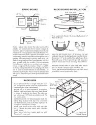
Step Seven: Radio <strong>and</strong> SCU<br />
Installation<br />
The Sail Control Unit most often<br />
used with the S/B is the swinging arm<br />
variety. The best reason to opt for the<br />
swinging arm over the drum type is that<br />
the jib boom is noticeably shorter than<br />
the main boom. The span from jib tack<br />
swivel back to the jib sheet attachment<br />
point is about 13 inches. The span from<br />
gooseneck aft to where the mainsheet is<br />
attached to the main boom is about 19<br />
inches. With a swinging arm sail control<br />
there are holes spaced about a half-inch<br />
apart. Using the hole 4” out from the<br />
arm’s pivot will provide the ideal 15” of<br />
travel for the jib sheet as the arm rotates<br />
through a range of 160 degrees. Using the<br />
hole 5-1/2” out on the arm provides 21”<br />
of ideal mainsheet travel. Using an SCU<br />
having a single arm mounted to one side<br />
of the boat, versus a double or two sided<br />
arm mounted on the centerline, allows<br />
more convenient access to the keel bolts.<br />
The piece of 1/8” plywood used as<br />
an SCU mounting board, Wooden Part<br />
WB, needs to have a hole cut out, in<br />
order to accommodate the electronics<br />
on the underside of the SCU. Also, two<br />
holes need to be made in the aft end<br />
of the board for the screws to secure it<br />
to K2. Two slots, instead of holes, need<br />
to be made in the forward end so as to<br />
allow the board to be slipped in or out<br />
from under two screw heads permanently<br />
set in T1. Since these two forward<br />
screws will be out of easy reach<br />
of a screwdriver, the slots on the end<br />
of the board make removing <strong>and</strong> reinstalling<br />
the SCU a simple matter.<br />
The 1/8” plywood radio board,<br />
Wooden Part RB, will be screwed at its<br />
corners to K2 <strong>and</strong> K3. The forward edge<br />
<strong>and</strong> the aft edge of this board need to<br />
be notched in order to clear the keel bolt<br />
wing nuts. Make a cutout to accommodate<br />
the rudder servo. Install the receiver<br />
<strong>and</strong> battery to either side of the rudder<br />
servo with Velcro. Use a length of fiberglass<br />
arrow shaft <strong>and</strong> nylon clevis fittings<br />
to make a rudder pushrod. Depending<br />
on the height of the servo <strong>and</strong> the height<br />
of the rudder control arm, it might be<br />
necessary to s<strong>and</strong> away a portion of T7’s<br />
underside so as to keep it from rubbing<br />
against the control rod.<br />
There are a variety of different ways<br />
of routing the sheets from the SCU to the<br />
booms. The method used here provides<br />
for the sheets to be dead-ended at the<br />
booms <strong>and</strong> be adjusted by tying off to<br />
deck mounted cleats. One end of the jib<br />
sheet gets hooked to a screw eye on the<br />
jib boom. From there, it passes through<br />
a hole in the deck (All holes in the deck<br />
will be drilled later after the deck is installed).<br />
From there it goes down to the<br />
turning block mounted on Wooden Part<br />
A <strong>and</strong> makes a 90-degree turn aft to the<br />
swinging arm. It then makes a 180-degree<br />
turn through a rounded hole in the<br />
arm <strong>and</strong>, then, forward in the direction<br />
of the turning block to the screw eye installed<br />
in Wooden Block Part A. From<br />
the screw eye, it can be led through another<br />
hole in the deck where it can then<br />
be tied to a conveniently accessible cleat<br />
near the mast.<br />
The main sheet runs from the main<br />
boom directly down through the deck<br />
<strong>and</strong> all the way forward to the turning<br />
block on Wooden Part A. After being<br />
led through the turning block, it goes<br />
back aft <strong>and</strong> through a hole in the<br />
arm. From the arm, it goes 180 degrees<br />
forward to that same screw eye it will<br />
share with the jib sheet <strong>and</strong>, then, up<br />
through a hole in the deck to its own<br />
cleat. The lead of the mainsheet might<br />
look a little convoluted, but it works.<br />
Those deck-mounted cleats make it<br />
easy to adjust sheets between races.<br />
A length of inner-section, flexible,<br />
nylon tubing push-rod allows a sheet to<br />
run through it with very little friction—<br />
even around turns <strong>and</strong> bends. Use it as<br />
“sheet plumbing.” Use CA glue to hold<br />
<strong>American</strong> <strong>Model</strong> <strong>Yachting</strong> <strong>Association</strong> © 2007 <br />
Issue 147 17
nylon tubing in place where it passes<br />
through holes in the wood.<br />
Step Eight: Gluing On the Deck<br />
The gr<strong>and</strong> finale of all this preparation<br />
work is the installation of the deck.<br />
At this time, it is a good idea to waterproof<br />
all wood surfaces—all sides—with<br />
a coat of slow-setting epoxy glue. (The<br />
waterproof slow-setting epoxy should<br />
be able to cover up the sins of the notso-waterproof<br />
quick-set epoxy used in<br />
various places in the assembly process.)<br />
Leave bare of glue the top surfaces of<br />
the sheer strips <strong>and</strong> the stringers. A special<br />
s<strong>and</strong>ing block should be used in order<br />
to prepare the sheer strips for installation<br />
of the deck. To a foot-long piece<br />
of wood “one-by-two,” cover 6” of a<br />
wide side with coarse s<strong>and</strong>paper. While<br />
the portion of this s<strong>and</strong>ing block bare<br />
of s<strong>and</strong>paper rides along the stringer<br />
<strong>and</strong> the portion having the s<strong>and</strong>paper<br />
makes contact with the top of a sheer<br />
strip, go around the entire boat, s<strong>and</strong>ing<br />
the top of the sheer strip. While s<strong>and</strong>ing,<br />
look to see that there are no high spots<br />
on the wood that might prevent the fiberglass<br />
deck from making contact with<br />
the fiberglass hull. Pay careful attention<br />
to the areas near the bow <strong>and</strong> the transom<br />
where the deck will meet the hull.<br />
Because the deck material bends only so<br />
much, these areas need be nearly flat.<br />
Apply a double layer of masking<br />
tape all around the hull, keeping the<br />
tape flush with the hull’s top edge. Later,<br />
once the deck is glued down <strong>and</strong> ready<br />
for the deck overhang to be trimmed<br />
away, this tape will provide a visual signal<br />
that it’s time to switch the s<strong>and</strong>ing<br />
block from coarse to fine s<strong>and</strong>paper.<br />
Carefully position the deck on the<br />
hull <strong>and</strong> use a few pieces of tape to hold<br />
it in place. Drill a lead hole 12” aft of the<br />
bow where the jib-tack deck fitting is to<br />
be installed. Then use a larger drill to<br />
enlarge the hole in the deck material to<br />
clearance-hole size. Use a small screw to<br />
temporarily fasten the deck to the stringer.<br />
Important: A hole in fiberglass must<br />
be bigger than the diameter of any screw<br />
passing through it. Otherwise, as you<br />
drive in the<br />
screw, you<br />
risk chipping<br />
the<br />
fiberglass<br />
s u r f a c e .<br />
Rely on<br />
the smaller<br />
hole drilled<br />
in the wood<br />
under the<br />
hole in the<br />
fiberglass<br />
to provide<br />
bite for<br />
the screw<br />
thread. Do<br />
l i k e w i s e<br />
with a screw<br />
at the center<br />
of the transom top where the backstay<br />
fitting will eventually be installed. These<br />
two screws will serve as guides when<br />
lowering the deck into place on top of<br />
wet glue. And, they will keep the deck<br />
centered <strong>and</strong> stationary as duct tape is<br />
being applied during the deck-tohull<br />
gluing process.<br />
Have h<strong>and</strong>y a big roll of duct<br />
tape. Mix up about two ounces of<br />
slow-set epoxy with enough microballoons<br />
added so that it is very<br />
slow to drip or run. With an acid<br />
brush, first apply glue to the top<br />
<strong>and</strong> sides of stringers S1 <strong>and</strong> S2.<br />
Use a dabbing or scraping technique<br />
to apply a good quantity of<br />
glue to the tops of the sheer strips<br />
<strong>and</strong> transom. With the deck bottom-up<br />
on the workbench, brush<br />
glue all around the one-inch outside<br />
edges where it will meet the<br />
sheer strips <strong>and</strong> along the deck<br />
centerline where it will meet the<br />
stringers. H<strong>and</strong>ling the deck by the<br />
hatch opening with one h<strong>and</strong>, turn<br />
it over, right side up. Drop a screw into<br />
the pre-drilled hole in the deck intended<br />
for the jib tack fitting. Drop a screw into<br />
the pre-drilled hole in the deck intended<br />
for the backstay fitting. Carefully lower<br />
the bow end of the deck over the hull<br />
<strong>and</strong> line up the screw with the hole predrilled<br />
in the bow stringer. While holding<br />
up the aft end of the deck a few<br />
inches above the hull, give the screw a<br />
few turns so as to keep the bow stationary.<br />
Avoid smearing the glue as you finish<br />
lowering the deck while keeping it<br />
in line with the screw intended for the<br />
backstay fitting. When both screws are<br />
tightened snug, the deck will not slide<br />
out of alignment.<br />
Grab the roll of duct tape. Tear off<br />
an 18” length. Starting from the area of<br />
the hatch, <strong>and</strong> applying the tape across<br />
the beam; use it to bring down <strong>and</strong> clamp<br />
the deck to both sides of the hull. Apply<br />
more tape strips, while working from<br />
this first tape, towards the bow <strong>and</strong> alternately<br />
towards the stern. Leave about<br />
one inch between tapes so that a portion<br />
of the joint is visible all around the boat.<br />
The space between tapes will allow you to<br />
see if the tape has stretched <strong>and</strong> allowed<br />
any small gaps to develop anywhere<br />
along the joint. In order to correct any<br />
gaps that may have developed, it will be<br />
necessary to pull the tape away, stretch it<br />
tight, <strong>and</strong> reattach it. Once the tapes have<br />
made a Zebra pattern from bow to stern<br />
check for any gaps; then go ahead <strong>and</strong><br />
double up on the tape. The stuff is cheap.<br />
Cover the spaces between the first layer<br />
of tapes <strong>and</strong> make the boat look like a<br />
mummy. When finished with the taping,<br />
Photo by Mike Kelley<br />
18 Issue 147 <br />
<strong>Model</strong> <strong>Yachting</strong> Magazine © Spring Issue, 2007
RMG SAILWINCH<br />
SmartWinch<br />
High speed, high torque intelligent winches .<br />
www.users.bigpond.com/rmgsw<br />
66 Radford Rd rmgsw@bigpond.com<br />
Angaston 5353 ph: 61 8 8564 2444<br />
SOUTH AUSTRALIA fax: 61 8 8564 3474<br />
turn the boat upside down <strong>and</strong> leave it<br />
that way overnight. With the boat upside<br />
down, glue will flow <strong>and</strong> create a filet at<br />
the deck-to-sheer-strip joint.<br />
The next day is the earliest time to<br />
right the boat, deck up, <strong>and</strong> to peel off<br />
the duct tape. Carefully start s<strong>and</strong>ing<br />
away the excess deck overhang <strong>and</strong> excess<br />
hardened epoxy that has squeezed<br />
overboard. Resist the urge to go at it with<br />
a power disc s<strong>and</strong>er. Eighty-grit s<strong>and</strong>paper<br />
on a s<strong>and</strong>ing block is a low-risk way<br />
to do the job. Apply s<strong>and</strong>ing pressure<br />
only in a downward motion from deck<br />
towards hull. Think in terms of pushing<br />
down on the glue joint <strong>and</strong> not pushing<br />
in the direction of opening the glue joint.<br />
Rod Carr, Sailmaker<br />
3011-177th Ave. NE<br />
Redmond, WA 98052-5825<br />
ARR SAILS<br />
Phone: (425) 881-2846<br />
Fax: (425) 869-7306<br />
E-mail: RodCarr@CarrSails.com<br />
Web Site: http://CarrSails.com<br />
Quality <strong>Model</strong> Yacht Sails For ALL R/C Racing Classes, Scale <strong>and</strong> Vintage Since 1969<br />
Hitec's New 4 <strong>and</strong> 6 Channel 75MHz Radio Systems<br />
Both Systems come complete with: Two HS-322 servos, one 8 Ch. Supreme receiver,<br />
transmitter NiCad batteries, one CG-25 "overnight" A/C charger, AA "dry"<br />
receiver battery holder, <strong>and</strong> Hitec's "Two Year" Warranty<br />
Laser 4 Ch. # 156751 Laser 6 Ch. # 157751<br />
As the excess is s<strong>and</strong>ed away, keep an<br />
eye on the masking tape. When you see<br />
scratches on the tape, it is time to switch<br />
to finer 120-grit s<strong>and</strong>paper <strong>and</strong> start<br />
s<strong>and</strong>ing in a fore <strong>and</strong> aft direction.<br />
This article about putting together a<br />
S/B short kit was first written in 1979. It<br />
was published as a booklet available from<br />
the AMYA Ship’s Store. At that time, we<br />
had three reliable sources of deck <strong>and</strong><br />
rigging hardware: Vortex <strong>Model</strong> Engineering,<br />
Probar Design, <strong>and</strong> A.J. Fisher.<br />
By the time the article was revised <strong>and</strong><br />
reprinted as a two-part article in the Fall<br />
1999, Issue No. 117 <strong>and</strong> Winter 1999, Issue<br />
No. 118 of <strong>Model</strong> <strong>Yachting</strong>, Vortex<br />
<strong>and</strong> Probar were gone from the market,<br />
Get More <strong>and</strong> Pay Less With Hitec's Affordable, Feature Packed Laser Radios.<br />
leaving A.J. Fisher as the only source of<br />
rigging <strong>and</strong> deck hardware. Today, A.J.<br />
Fisher hardware is also no longer available.<br />
This, the third version of the article,<br />
will also be printed in two parts. Part II<br />
of Assembling a <strong>Santa</strong> <strong>Barbara</strong> will be<br />
published in the next issue, No. 148, of<br />
<strong>Model</strong> <strong>Yachting</strong>. Part II will describe the<br />
rigging of a S/B while using hardware fittings<br />
available today from Ludwig Mfg.<br />
<strong>and</strong> GBMY.<br />
In addition to being about rigging<br />
the boat’s deck <strong>and</strong> spars with fittings<br />
<strong>and</strong> hardware, Part II will also describe<br />
loading <strong>and</strong> solidifying the lead shot<br />
ballast in the Hartman keel.<br />
TOUCH YOUR DREAMS<br />
12115 Paine Street, Poway, CA 92064 (858) 748-6948<br />
<strong>American</strong> <strong>Model</strong> <strong>Yachting</strong> <strong>Association</strong> © 2007 <br />
Issue 147 19