FyreWrap Elite Grease Duct Insulation - Unifrax
FyreWrap Elite Grease Duct Insulation - Unifrax
FyreWrap Elite Grease Duct Insulation - Unifrax

You also want an ePaper? Increase the reach of your titles
YUMPU automatically turns print PDFs into web optimized ePapers that Google loves.
<strong>FyreWrap</strong> ® <strong>Elite</strong> ® 1.5<br />
<strong>Duct</strong> <strong>Insulation</strong> – <strong>Grease</strong><br />
<strong>Duct</strong> ASTM E 2336 System<br />
Introduction<br />
<strong>Unifrax</strong>’s <strong>FyreWrap</strong> ® <strong>Elite</strong> ® 1.5 <strong>Duct</strong> <strong>Insulation</strong> is a two-layer<br />
flexible enclosure for one- and two-hour rated commercial<br />
kitchen grease ducts. <strong>FyreWrap</strong> <strong>Elite</strong> 1.5 <strong>Duct</strong> <strong>Insulation</strong> is<br />
tested per ASTM E 2336 and is acceptable as an alternate to<br />
a traditional fire-rated shaft. Installed as a two-layer system,<br />
<strong>FyreWrap</strong> <strong>Elite</strong> 1.5 complies with AC101 and the 2006 and<br />
2009 Editions of the International Mechanical Code (IMC)<br />
and Uniform Mechanical Code (UMC). <strong>FyreWrap</strong> <strong>Elite</strong> 1.5<br />
<strong>Duct</strong> <strong>Insulation</strong> offers the following product features:<br />
2-hour fire-resistance rating<br />
Alternate to shaft enclosure<br />
Complies with 2006 and 2009 IMC and UMC<br />
Tested per ASTM E 2336<br />
Two-layer system; inner layer utilizes butt joint<br />
High-temperature, biosoluble insulation<br />
Zero clearance to combustibles, at any location<br />
GREENGUARD listed for Microbial Resistance<br />
Typical Product Properties<br />
Product Information Sheet<br />
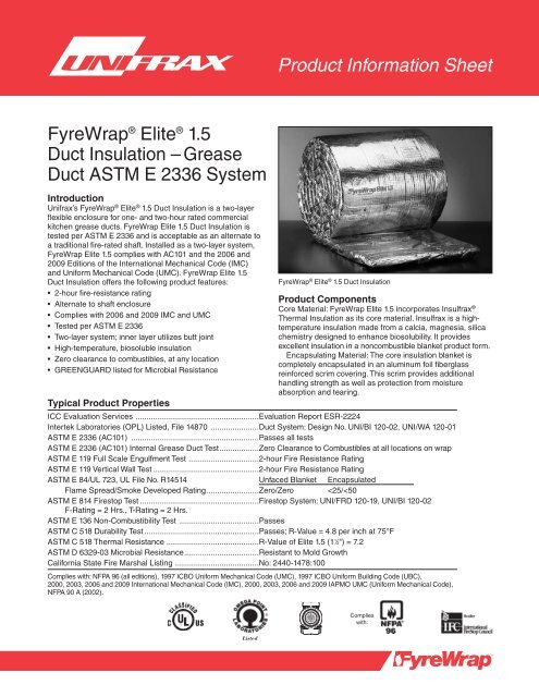
<strong>FyreWrap</strong> ® <strong>Elite</strong> ® 1.5 <strong>Duct</strong> <strong>Insulation</strong><br />
Product Components<br />
Core Material: <strong>FyreWrap</strong> <strong>Elite</strong> 1.5 incorporates Insulfrax ®<br />
Thermal <strong>Insulation</strong> as its core material. Insulfrax is a hightemperature<br />
insulation made from a calcia, magnesia, silica<br />
chemistry designed to enhance biosolubility. It provides<br />
excellent insulation in a noncombustible blanket product form.<br />
Encapsulating Material: The core insulation blanket is<br />
completely encapsulated in an aluminum foil fiberglass<br />
reinforced scrim covering. This scrim provides additional<br />
handling strength as well as protection from moisture<br />
absorption and tearing.<br />
ICC Evaluation Services ........................................................Evaluation Report ESR-2224<br />
Intertek Laboratories (OPL) Listed, File 14870 ......................<strong>Duct</strong> System: Design No. UNI/BI 120-02, UNI/WA 120-01<br />
ASTM E 2336 (AC101) ..........................................................Passes all tests<br />
ASTM E 2336 (AC101) Internal <strong>Grease</strong> <strong>Duct</strong> Test..................Zero Clearance to Combustibles at all locations on wrap<br />
ASTM E 119 Full Scale Engulfment Test ................................2-hour Fire Resistance Rating<br />
ASTM E 119 Vertical Wall Test ................................................2-hour Fire Resistance Rating<br />
ASTM E 84/UL 723, UL File No. R14514 Unfaced Blanket Encapsulated<br />
Flame Spread/Smoke Developed Rating........................Zero/Zero
Typical Product Parameters<br />
Thickness 1.5"<br />
Nominal Density 6pcf<br />
Standard Product Form Scrim Encapsulated<br />
Product Availability 24"w x 25LF<br />
48"w x 25LF<br />
Installation<br />
The <strong>FyreWrap</strong> <strong>Elite</strong> 1.5 <strong>Duct</strong> <strong>Insulation</strong> ASTM E 2336 System<br />
consists of a fully encapsulated, two-layer system applied<br />
directly to the duct surface. The insulation system may be<br />
installed at zero clearance to combustibles at any point. To<br />
minimize waste, <strong>FyreWrap</strong> <strong>Elite</strong> 1.5 should be rolled out tautly<br />
before measuring and making any material cuts.<br />
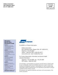
Butt Joint Both Layers Wrap Option<br />
(For ducts 24" x 24" or less)<br />
For ducts 24" x 24" or less, both layers of wrap can be<br />
installed with transverse (perimeter) joints butted and<br />
minimum 3" longitudinal overlaps located on the topside<br />
of horizontal ducts. Stagger transverse butt joints by 12"<br />
between the first and second layers of wrap. Both layers of<br />
wrap can be temporarily secured with 1" wide filament tape.<br />
After the second layer of wrap is installed, place carbon or<br />
stainless steel bands (min. ½" wide, .015" thick) on both sides<br />
of all transverse butt joints 2½" on center from the joint and in<br />
the field area between the butt joints 9" on center. Tighten<br />
banding to firmly hold the wrap system in place but not so<br />
tight as to cut or damage the blanket and secure with<br />
minimum 1" long steel crimp clips. Seal all second layer<br />
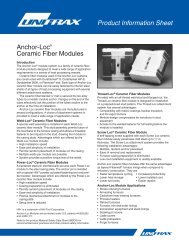
Figure 1. Butt Joint Wrap Option<br />
4<br />
Form C-1495<br />
Effective 4/11<br />
© 2011 <strong>Unifrax</strong> I LLC<br />
All Rights Reserved<br />
Printed in USA<br />
Page 2 of 8<br />
5<br />
2<br />
3<br />
5 6<br />
2 1 2 "<br />
2 1 2 "<br />
1<br />
9"<br />
<strong>FyreWrap</strong> ® <strong>Elite</strong> ® 1.5 <strong>Duct</strong> <strong>Insulation</strong><br />
Commercial Kitchen <strong>Grease</strong> <strong>Duct</strong> System<br />
ASTM E 2336/ICCES AC1 01 System<br />
1- and 2-Hour Fire-Rated Enclosure, Shaft Alternative<br />
Zero Clearance To Combustibles<br />
Butt Joint System (Both Layers, Max. 24" x 24" <strong>Duct</strong>)<br />
9"<br />
2 1 2 "<br />
2 1 2 "<br />
transverse butt joints and exposed blanket edges with<br />
minimum 3" wide aluminum foil tape. Pins are NOT required<br />
when utilizing this installation method.<br />
Overlap Techniques<br />
The first layer can be installed with transverse (perimeter)<br />
joints butted and minimum 3" longitudinal overlaps on the<br />
topside of horizontal ducts. All overlaps for the second, or<br />
outer layer, are required to be a minimum of 3". For the<br />
second layer, transverse (perimeter) overlaps of adjacent<br />
blankets may be installed using one of the following three<br />
methods and as shown in Figure 2.<br />
Telescoping Overlap Wrap Technique:<br />
This wrap technique is the most common method of installing<br />
<strong>FyreWrap</strong> <strong>Elite</strong> 1.5 where each adjacent blanket has one<br />
edge exposed and one edge covered by the next blanket, to<br />
form a 3" overlap.<br />
Cut the first piece of inner layer insulation to a length<br />
sufficient to wrap around the duct and provide a 3" longitu -<br />
dinal overlap on the topside of the duct. Install the adjacent<br />
inner layer piece so that the blanket edge is butted against<br />
the preceding piece, forming a tight perimeter joint. This<br />
piece also requires a 3" longitudinal overlap on the topside<br />
of the duct. Space the starting edge of the outer layer a<br />
maximum 3" from the exposed edge of the inner layer. All<br />
joints on the second layer require a minimum 3" overlap.<br />
Ends of the outer overlaps occur on the topside of the<br />
horizontal section and backside of the vertical section of the<br />
duct, alternating nominal 8" on either side of the longitudinal<br />
centerline with each successive wrap piece. All cut edges<br />
shall be sealed with aluminum foil tape.<br />
2 3<br />
5<br />
9"<br />
2 3<br />
Butt Joint<br />
Adjacent Blanket Pieces<br />
FP-693<br />
Legend:<br />
1 <strong>FyreWrap</strong> ® <strong>Elite</strong> ® 1.5 <strong>Duct</strong> <strong>Insulation</strong>, Two Layers<br />
(each 1.5", total thickness = 3")<br />
2 Filament Tape (Temporary Hold)<br />
3 1 ⁄2" Carbon or SS Banding Straps (Permanent Hold)<br />
4 3" Minimum Longitudinal Overlap<br />
5 1" Compressed Butt Joint<br />
6 3" Wide Aluminum Foil Tape at 2nd Layer Transverse Butt Joints<br />
2 1 2 "<br />
2 1 2 "<br />
6
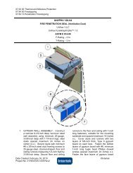
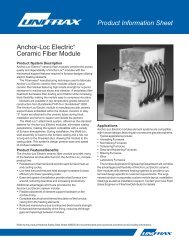
Figure 2. 2-layer detail<br />
Legend:<br />
1 <strong>FyreWrap</strong> ® <strong>Elite</strong> ® 1.5 <strong>Duct</strong> <strong>Insulation</strong>, Two Layers<br />
(each 1.5", total thickness = 3")<br />
2 Filament Tape (Temporary Hold)<br />
3 Carbon or SS Banding Straps (Permanent Hold)<br />
4 3" Minimum Longitudinal Overlap<br />
5 3" Minimum Transverse Overlap<br />
6 1" Compressed Butt Joint<br />
7 Steel Hanger Rod<br />
8 Steel Angle<br />
9 6" wide <strong>FyreWrap</strong> ® <strong>Elite</strong> ® 1.5 Collar<br />
Checkerboard Overlap Wrap Technique:<br />
This installation uses a 3" overlap pattern with both edges<br />
of each alternating blanket covered by each adjacent blanket<br />
whose edges are exposed. The overlap joints in alternate<br />
layers of blanket resemble a checkerboard pattern in the<br />
completed installation. This technique is often utilized when<br />
a small section of duct wrap must be repaired.<br />
Butt Splice with Collar Wrap Technique:<br />
This wrap technique permits installation with the blanket<br />
edges butted together and a 6" wide collar of blanket that<br />
is centered over the butt splice, overlapping each adjacent<br />
blanket 3". The collar can be field fabricated from <strong>FyreWrap</strong><br />
<strong>Elite</strong> 1.5 <strong>Duct</strong> <strong>Insulation</strong> rolls or purchased separately.<br />
Vertical <strong>Duct</strong> Runs<br />
For vertical runs, the insulation can be applied to the duct in<br />
a continuous length applied parallel with the length of the<br />
duct as opposed to wrapping around the duct. All overlaps<br />
are to be maintained at a minimum 3" and are to occur a<br />
minimum of 6" from any corner of the duct. The second layer<br />
is to be centered over the overlapped seam of the first layer.<br />
Pins spaced a maximum 8" o.c. are to be placed at the<br />
centerline of all vertically oriented overlaps.<br />
Form C-1495<br />
Effective 4/11<br />
© 2011 <strong>Unifrax</strong> I LLC<br />
All Rights Reserved<br />
Printed in USA<br />
Page 3 of 8<br />
<strong>FyreWrap</strong> ® <strong>Elite</strong> ® 1.5 <strong>Duct</strong> <strong>Insulation</strong><br />
Commercial Kitchen <strong>Grease</strong> <strong>Duct</strong> System<br />
ASTM E 2336 System/ICC ES AC1 01<br />
1- and 2-Hour Fire-Rated Enclosure, Shaft Alternative<br />
Zero Clearance To Combustibles<br />
INSTALLATION METHODS:<br />
Butt Joint – 3" Overlap<br />
Butt Joint – Collar 3" Overlap on all layers<br />
FP-421<br />
Attachment Options<br />
Three attachment options are available for installers. Choices<br />
are limited by the duct width dimension. Details on each<br />
option are provided below.<br />
Banding Only: For <strong>Duct</strong> Widths 24" or Less<br />
To temporarily secure the insulation, optional use of filament<br />
tape is permitted. Place carbon steel or stainless steel bands<br />
(min. 1 ⁄2" wide, nom. 0.015" thick) 11 ⁄2" from each edge of each<br />
second layer blanket overlap. Place additional bands in the<br />
field area between the second layer overlaps on maximum<br />
101 ⁄2" centers. Tighten banding to firmly hold the wrap system<br />
in place but not so tight as to cut or damage the blanket and<br />
secure with minimum 1" long steel crimp clips. Pins are NOT<br />
required when this banding technique is used.<br />
Banding and Pins: For <strong>Duct</strong> Widths ≤ 49"<br />
Weld 12-gauge steel insulation pins to the underside of<br />
horizontal runs and backside (side of duct having largest<br />
dimensions) of vertical runs. Place pins at maximum 12" rows<br />
and on maximum 10 1 ⁄2" centers. To temporarily secure the<br />
insulation, optional use of filament tape is permitted. Impale<br />
<strong>FyreWrap</strong> <strong>Elite</strong> 1.5 <strong>Duct</strong> <strong>Insulation</strong> over the pins and hold in
place with minimum 21 ⁄2" square or 1.5" round galvanized<br />
steel speed clips (washers). Turn down or cut off exposed<br />
ends of pins to eliminate safety hazards. Locate carbon steel<br />
or stainless steel bands (min. 1 ⁄2" wide, nom. 0.015" thick) 11 ⁄2"<br />
from each edge of second layer overlap joints. Locate a<br />
second band midpoint between the second layer over lapped<br />
joints, approximately 101 ⁄2" on center. Tighten banding to<br />
firmly hold the wrap system in place but not so tight as to<br />
cut or damage the blanket and secure with minimum 1" long<br />
steel crimp clips. Cup head style pins are also permitted and<br />
shall be located at the same spacing as pre-welded pins.<br />
Pins Only: For <strong>Duct</strong> Widths > 49"<br />
Weld 12-gauge steel insulation pins on all sides of the duct.<br />
Place insulation pins in rows (perpendicular to the length of<br />
the duct) spaced maximum 101 ⁄2" on center. Pins in each row<br />
are maximum 5" from each duct edge and maximum 8" on<br />
center. Locate insulation overlaps so they are centered on<br />
the pins. Impale <strong>FyreWrap</strong> <strong>Elite</strong> 1.5 <strong>Duct</strong> <strong>Insulation</strong> over the<br />
pins and hold in place with minimum 21 ⁄2" square or 1 ⁄2"<br />
round galvanized steel speed clips (washers) to keep the<br />
system from sagging. Turn down or cut off exposed ends<br />
of pins to eliminate safety hazards. Cup head style pins are<br />
also permitted and shall be located at the same spacing as<br />
pre-welded. The pins only attachment method can be used<br />
for duct widths less than 49", but is optional.<br />
Access Door<br />
Field fabricated and prefabricated grease duct access doors<br />
are permitted for use with <strong>FyreWrap</strong> <strong>Elite</strong> 1.5 <strong>Duct</strong> <strong>Insulation</strong>.<br />
Installation details are provided below and in Figure 3.<br />
Field fabricated access doors are protected with three<br />
layers of <strong>FyreWrap</strong> <strong>Elite</strong> 1.5 <strong>Duct</strong> <strong>Insulation</strong>. A gasket of 0.5"<br />
thick unfaced <strong>FyreWrap</strong> or ceramic fiber blanket is initially<br />
installed between the duct and the access door cover. Weld<br />
threaded rod to each corner of the access door opening.<br />
For additional information about product performance or<br />
to identify the recommended product for your fire protection<br />
application, please contact <strong>Unifrax</strong> at 716-278-3800 and ask<br />
for Fire Protection Application Engineering.<br />
Form C-1495<br />
Effective 4/11<br />
© 2011 <strong>Unifrax</strong> I LLC<br />
All Rights Reserved<br />
Printed in USA<br />
Page 4 of 8<br />
Cover with hollow steel tubes (optional) for easy removal of<br />
blanket. Weld at least four steel insulation pins to the outside<br />
of the door cover panel, 1" from each corner. Cut through the<br />
two layers of <strong>FyreWrap</strong> <strong>Elite</strong> 1.5 <strong>Duct</strong> <strong>Insulation</strong> already<br />
covering the duct and access door opening. Leave the interior<br />
piece in place. Cut back the outer layer to form an opening<br />
with perimeter dimensions that extend 1" beyond the inner<br />
layer. Cut a piece of <strong>FyreWrap</strong> <strong>Elite</strong> 1.5 <strong>Duct</strong> <strong>Insulation</strong> that<br />
matches the dimensions of the opening and install over pins<br />
to fit tightly within the existing material. Cut an additional<br />
piece of insulation with perimeter dimensions that extend<br />
1" beyond the layer below. Install over the insulation pins.<br />
Throughout the installation process, seal all cut edges with<br />
aluminum foil tape. Secure with washers and bend over<br />
excess pin lengths to eliminate safety hazards. Place washers<br />
on threaded rod and secure with nuts. Do not install banding<br />
over this area. See Figure 3 for details.<br />
Prefabricated – <strong>Duct</strong>mate Ultimate and <strong>Duct</strong>mate F2-HT<br />
prefabricated access doors are permitted and must be<br />
installed in accordance with <strong>Duct</strong>mate Industries, Inc.<br />
installation instructions and the applicable code. The<br />
prefabricated access door is protected with three layers<br />
of <strong>FyreWrap</strong> <strong>Elite</strong> 1.5 <strong>Duct</strong> <strong>Insulation</strong>. The first layer is cut<br />
to the size of the door. A successive layer (two additional<br />
layers) is sized to create an overlap of 1" beyond the layer<br />
immediately below. All edges of insulation blanket must be<br />
protected with aluminum foil tape. A No. 16 gauge outer plate<br />
the same dimension as the outer layer of insulation blanket<br />
is held in place over the insulation using threaded rod and<br />
wing nuts. The outer plate is supplied with the Ultimate<br />
door and F2-HT doors. Access doors are available from<br />
<strong>Duct</strong>mate Industries, Inc. Contact www.ductmate.com or<br />
1-800-245-3188 for additional information or local distributors.<br />
Ask for the Access Door Product Line Manager.<br />
Refer to the product Material Safety Data Sheet (MSDS)<br />
for recommended work practices and other product safety<br />
information.
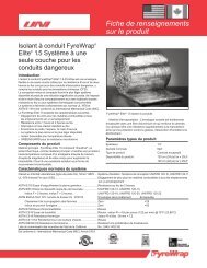
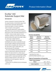
Figure 3. Access Door<br />
<strong>Duct</strong> Support<br />
Horizontal duct support systems do not require <strong>FyreWrap</strong><br />
insulation when constructed using a minimum 3 ⁄8" diameter<br />
uninsulated all-thread steel rod and 1 1 ⁄2" x 1 1 ⁄2" x 1 ⁄8"<br />
uninsulated steel angle spaced a maximum 60" on center<br />
along the length of the duct. A minimum clearance of 1" is<br />
required between the protected duct and the steel rod. To<br />
increase hanger spacing to 72" on center, 1 ⁄2" all-thread steel<br />
rod and 2" x 2" x 1 ⁄4" steel angle are required. Vertical duct<br />
support systems do not require <strong>FyreWrap</strong> insulation when<br />
constructed using minimum 1 1 ⁄2" x 1 1 ⁄2" x 1 ⁄4" steel angle<br />
brackets located on opposite sides of the duct, on the top<br />
and bottom of each floor-ceiling assembly. The supports are<br />
attached to the duct with welds. Maximum spacing between<br />
vertical supports shall be established by structural calculations<br />
in accordance with the applicable code, that are submitted<br />
to the building official for approval. See Figure 4 for details.<br />
For all other duct support configurations, please contact<br />
<strong>Unifrax</strong> at 716-278-3800 and ask for Fire Protection<br />
Application Engineering.<br />
Form C-1495<br />
Effective 4/11<br />
© 2011 <strong>Unifrax</strong> I LLC<br />
All Rights Reserved<br />
Printed in USA<br />
Page 5 of 8<br />
Ultimate<br />
Door System<br />
Legend:<br />
1 Access Door Opening<br />
2 All Thread Rods<br />
3 Access Door Cover Panel 16 Gauge (field fab. only)<br />
4 <strong>Insulation</strong> Pins – Welded to Cover<br />
5 First Layer <strong>FyreWrap</strong> ® <strong>Elite</strong> ® 1.5<br />
6 Second Layer <strong>FyreWrap</strong> ® <strong>Elite</strong> ® 1.5, 1" Overlap<br />
7 Third Layer <strong>FyreWrap</strong> ® <strong>Elite</strong> ® 1.5, 1" Overlap<br />
8 Speed Clips/Washers<br />
9 Cut Edges Sealed With Aluminum Foil Tape<br />
10 Spool pieces for threaded rods (optional field fab. only)<br />
11 Wing Nuts<br />
12 Washers<br />
13 <strong>Insulation</strong> plate<br />
14 Unfaced <strong>FyreWrap</strong> blanket or Ceramic fiber gasket, 1 ⁄2" thick<br />
15 Prefabricated access door<br />
<strong>FyreWrap</strong> ® <strong>Elite</strong> ® 1.5 <strong>Duct</strong> <strong>Insulation</strong><br />
Commercial Kitchen <strong>Grease</strong> <strong>Duct</strong> System<br />
Access Door Systems<br />
<strong>Duct</strong>mate F2-HT<br />
Door System<br />
Field Fabricated<br />
Door System<br />
FP-426<br />
Firestop Systems<br />
Where ducts insulated with <strong>FyreWrap</strong> <strong>Elite</strong> 1.5 <strong>Duct</strong><br />
<strong>Insulation</strong> pass through fire-rated walls and floors, the<br />
penetration opening shall be firestopped to maintain the<br />
fire rating of the assembly. Firestop Systems acceptable<br />
for use with <strong>FyreWrap</strong> <strong>Elite</strong> 1.5 <strong>Duct</strong> <strong>Insulation</strong> ASTM<br />
E 2336 System at the time of printing are detailed below.<br />
See Figures 5-7 for details. Additional firestop systems<br />
may be developed and available for use. Contact <strong>Unifrax</strong><br />
at 716-278-3800 and ask for Fire Protection Application<br />
Engineering for additional details and assistance or visit<br />
the test lab web site for the latest documentation.
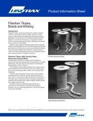
Figure 4. Firestop Installation<br />
Form C-1495<br />
Effective 4/11<br />
© 2011 <strong>Unifrax</strong> I LLC<br />
All Rights Reserved<br />
Printed in USA<br />
Page 6 of 8<br />
<strong>FyreWrap</strong> ® <strong>Elite</strong> ® 1.5 <strong>Duct</strong> <strong>Insulation</strong><br />
Typical <strong>Duct</strong> Support Details<br />
TYPICAL HORIZONTAL DUCT SUPPORT DETAILS<br />
Legend:<br />
1 Max. <strong>Duct</strong> Size (HxW) 49" x 49" 49" x 49"<br />
2 Steel Threaded Rod 3 ⁄8" diameter 1 ⁄2" diameter<br />
3 Steel Angle 1 1 ⁄2" x 1 1 ⁄2" x 1 ⁄8" 2" x 2" x 1 ⁄4"<br />
4 Support System 60" 72"<br />
Spacing (L)<br />
Figure 5. Firestop Installation<br />
<strong>FyreWrap</strong> ® <strong>Elite</strong> ® 1.5 <strong>Duct</strong> <strong>Insulation</strong><br />
Through Penetration Wall System<br />
Intertek (OPL) Design No. UNI/FRD 120-19<br />
2-Hour Fire Resistance Rating<br />
F-Rating = 2 Hrs. T-Rating = 2 Hrs.<br />
Legend:<br />
1 <strong>Grease</strong> <strong>Duct</strong>, max. 4900 in 2 area, 70" max width<br />
2 <strong>FyreWrap</strong> ® <strong>Elite</strong> ® 1.5 <strong>Duct</strong> <strong>Insulation</strong>, Two Layers<br />
3 Unfaced <strong>FyreWrap</strong> ® <strong>Elite</strong> ® 1.5 (3 7 ⁄8", compressed 48%)<br />
4 STI Spec Seal SSS, 5 ⁄8" depth<br />
5 Fire-Resistive Gypsum Wall Assembly<br />
6 Annular Space 0" to 3 1 ⁄2"<br />
TYPICAL VERTICAL DUCT SUPPORT DETAILS<br />
Legend:<br />
1 <strong>FyreWrap</strong> ® <strong>Elite</strong> ® 1.5 <strong>Duct</strong> <strong>Insulation</strong>, Two Layers<br />
2 <strong>Duct</strong> Support Mechanism<br />
3 Mechanical Fasteners & Washers<br />
4 <strong>Grease</strong> <strong>Duct</strong><br />
5 Fire Resistive Concrete Floor/Ceiling Assembly<br />
6 Firestop System<br />
7 Steel Banding and Clips<br />
FP-625<br />
FP-429
Figure 6. Firestop Installation<br />
6<br />
6<br />
6<br />
Form C-1495<br />
Effective 4/11<br />
© 2011 <strong>Unifrax</strong> I LLC<br />
All Rights Reserved<br />
Printed in USA<br />
Page 7 of 8<br />
4<br />
4<br />
3<br />
3<br />
<strong>FyreWrap</strong> ® <strong>Elite</strong> ® 1.5 <strong>Duct</strong> <strong>Insulation</strong> Through Penetration Firestops Wall<br />
Intertek Design No. UNI/BI 120-02 F-Rating = 2 Hrs. T-Rating = 2 Hrs.<br />
4<br />
Section “A-A”<br />
Option 1<br />
Section “A-A”<br />
Option 8<br />
4<br />
3<br />
Section “A-A”<br />
Option 7<br />
4<br />
2<br />
1<br />
1<br />
2<br />
1<br />
4<br />
A<br />
6<br />
1<br />
4<br />
3<br />
2<br />
3<br />
Legend:<br />
1 <strong>Grease</strong> <strong>Duct</strong>, max. 2401 in 2 area, 49" max width<br />
2 <strong>FyreWrap</strong> ® <strong>Elite</strong> ® 1.5 <strong>Duct</strong> <strong>Insulation</strong>, Two Layers<br />
3 Fire-Resistive Concrete, Gypsum, or SMU block wall assembly, 2 hr. rated<br />
4 Firestop Sealant, 5 ⁄8" depth, overlapping on wall and duct min. 1 ⁄2"<br />
3M Fire Barrier 1000NS or Hilti FS-ONE or STI SpecSeal or Tremco FyreSil<br />
5 Unfaced <strong>FyreWrap</strong> ® <strong>Elite</strong> ® 1.5 or 4 PCF Mineral Wool compressed<br />
50% option 1 and 33% options 2-8, recessed 5 ⁄8" from both sides of wall<br />
6 Annular space, 1 ⁄2" to 4 1 ⁄2"<br />
4<br />
Section “A-A”<br />
Option 2<br />
4<br />
4<br />
4<br />
2<br />
3<br />
5<br />
6 6<br />
Section “A-A”<br />
Option 6<br />
2<br />
1<br />
2<br />
1<br />
A<br />
6<br />
4<br />
6<br />
4<br />
4<br />
3<br />
Section “A-A”<br />
Option 3<br />
3<br />
3<br />
4<br />
4<br />
4<br />
Section “A-A”<br />
Option 4<br />
Section “A-A”<br />
Option 5<br />
2<br />
1<br />
2<br />
1<br />
1<br />
2<br />
FP-690
Figure 7. Firestop Installation<br />
3<br />
3<br />
3<br />
4<br />
<strong>FyreWrap</strong> ® <strong>Elite</strong> ® 1.5 <strong>Duct</strong> <strong>Insulation</strong> Through Penetration Firestops Floor<br />
Intertek Design No. UNI/BI 120-02 F-Rating = 2 Hrs. T-Rating = 2 Hrs.<br />
2<br />
6<br />
1<br />
Section “A-A”<br />
Option 1<br />
4<br />
4<br />
2<br />
Section “A-A”<br />
Option 8<br />
2<br />
6<br />
6<br />
Section “A-A”<br />
Option 7<br />
1<br />
1<br />
3<br />
3<br />
3<br />
4<br />
4<br />
4<br />
2<br />
2<br />
2<br />
1<br />
Legend:<br />
1 <strong>Grease</strong> <strong>Duct</strong>, max. 2401 in 2 area, 49" max width<br />
2 <strong>FyreWrap</strong> ® <strong>Elite</strong> ® 1.5 <strong>Duct</strong> <strong>Insulation</strong>, Two Layers<br />
3 Fire-Resistive Concrete Floor assembly, 2 hr. rated<br />
4 Firestop Sealant, 3 ⁄8" depth, overlapping on floor and duct min. 1 ⁄2"<br />
3M Fire Barrier 1000NS or Hilti FS-ONE or STI SpecSeal SSS or Tremco FyreSil<br />
5 Unfaced <strong>FyreWrap</strong> ® <strong>Elite</strong> ® 1.5 or 4 PCF Mineral Wool compressed<br />
50% option 1 and 33% options 2-8, recessed 3 ⁄8" from top side of floor<br />
6 Annular space, 1 ⁄2" to 4 1 ⁄2"<br />
1<br />
6<br />
Section “A-A”<br />
Option 2<br />
6<br />
Section “A-A”<br />
Option 6<br />
1<br />
A<br />
A<br />
5<br />
3<br />
3<br />
4<br />
4<br />
3<br />
2<br />
2<br />
4<br />
2<br />
6<br />
Section “A-A”<br />
Option 3<br />
Form C-1495<br />
Effective 4/11<br />
© 2011 <strong>Unifrax</strong> I LLC<br />
All Rights Reserved<br />
Printed in USA<br />
Page 8 of 8<br />
The following are registered trademarks of <strong>Unifrax</strong>: <strong>FyreWrap</strong>, <strong>Elite</strong> and Insulfrax.<br />
The test data shown are average results of tests conducted under standard procedures and are subject to variation. Results should not be used<br />
for specification purposes.<br />
Product Information Sheets are periodically updated by <strong>Unifrax</strong>. Before relying on any data or other information in this Product Information Sheet,<br />
you should confirm that it is still current and has not been superseded. A Product Information Sheet that has been superseded may contain<br />
incorrect, obsolete and/or irrelevant data and other information.<br />
6<br />
1<br />
1<br />
6<br />
Section “A-A”<br />
Option 4<br />
Section “A-A”<br />
Option 5<br />
1<br />
FP-691<br />
<strong>Unifrax</strong> I LLC<br />
Corporate Headquarters<br />
2351 Whirlpool Street<br />
Niagara Falls, New York 14305-2413<br />
Telephone: 716-278-3800<br />
Telefax: 716-278-3900<br />
Internet: www.unifrax.com<br />
Email: info@unifrax.com