Instruction Bulletin NF Panelboard H- or J ... - Schneider Electric
Instruction Bulletin NF Panelboard H- or J ... - Schneider Electric
Instruction Bulletin NF Panelboard H- or J ... - Schneider Electric

Create successful ePaper yourself
Turn your PDF publications into a flip-book with our unique Google optimized e-Paper software.
<strong>Instruction</strong> <strong>Bulletin</strong><br />
<strong>NF</strong> <strong>Panelboard</strong> H- <strong>or</strong> J-Frame Main<br />
Circuit Breaker Adapter Kit<br />
Installation onto an <strong>NF</strong> <strong>Panelboard</strong><br />
Class 1670<br />
Retain f<strong>or</strong> future use.<br />
Introduction This bulletin contains instructions f<strong>or</strong> installing a Square D ® brand<br />
H-frame (maximum 150 A) <strong>or</strong> J-frame (maximum 250 A) main circuit<br />
breaker adapter kit onto a Square D brand <strong>NF</strong> panelboard manufactured by<br />
<strong>Schneider</strong> <strong>Electric</strong>.<br />
Safety Precautions<br />
Kit Contents<br />
Tools Needed<br />
© 2008–2009 <strong>Schneider</strong> <strong>Electric</strong> All Rights Reserved<br />
DANGER<br />
HAZARD OF ELECTRIC SHOCK, EXPLOSION, OR ARC FLASH<br />
• Apply appropriate personal protective equipment (PPE) and follow safe electrical w<strong>or</strong>k practices. See <strong>NF</strong>PA 70E.<br />
• This equipment must only be installed and serviced by qualified electrical personnel.<br />
• Turn off all power supplying this equipment bef<strong>or</strong>e w<strong>or</strong>king on <strong>or</strong> inside equipment.<br />
• Always use a properly rated voltage sensing device to confirm power is off.<br />
• Replace all devices, do<strong>or</strong>s, and covers bef<strong>or</strong>e turning on power to this equipment.<br />
Failure to follow these instructions will result in death <strong>or</strong> serious injury.<br />
N150MH and N250MJ<br />
A. N150MH kit only—Three terminal kit (S37444) (1)<br />
B. N250MJ kit only—Three terminal kit (S37445) (1)<br />
C. Main circuit breaker connect<strong>or</strong> (1)<br />
D. Main circuit breaker connect<strong>or</strong> (1)<br />
E. Main circuit breaker connect<strong>or</strong> (1)<br />
F. 10-32 x 5/16-inch tapping screws (10)<br />
G. 1/4-20 x 3/4-inch tapping screws (6)<br />
H. 10-32 x 7/16-inch tapping screws (4)<br />
I. 8-32 x 3 1/4-inch tapping screws (2)<br />
J. 10-32 x 7/8-inch tapping screws (2)<br />
K. Main circuit breaker deadfront cover (1)<br />
L. Main circuit breaker mounting pan assembly (1)<br />
M. N150MH kit only—Main circuit breaker<br />
deadfront cover (1)<br />
N. “MAIN” circuit breaker label (1)<br />
O. Deadfront supp<strong>or</strong>t brackets (2)<br />
P. Rail extensions (2)<br />
Q. Rail splices (2)<br />
NOTE: Kit contents not shown to scale.<br />
A B<br />
K<br />
N O<br />
MAIN<br />
PRINCIPAL<br />
• Flat-head screwdriver<br />
#2 Square-head Robertson driver<br />
T<strong>or</strong>que wrench with 5/32-inch Allen driver<br />
L<br />
C<br />
P<br />
D<br />
M<br />
E<br />
80043-764-03<br />
05/2009<br />
Peru, IN, USA<br />
F G H<br />
Q<br />
I<br />
J<br />
ENGLISH
ENGLISH<br />
<strong>NF</strong> <strong>Panelboard</strong> H- <strong>or</strong> J-Frame Main Circuit Breaker Adapter Kit 80043-764-03<br />
Installing the Main Circuit Breaker Adapter Kit 05/2009<br />
Installing the Main Circuit Breaker Adapter Kit<br />
2<br />
2<br />
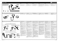
Turn off all power supplying this equipment bef<strong>or</strong>e w<strong>or</strong>king inside the panelboard; follow all lockout/tagout procedures.<br />
Deadfront assembly Main lug cover<br />
1<br />
Remove the deadfront assembly and retain the<br />
four screws f<strong>or</strong> reuse. Remove the main lug<br />
cover and discard the screws and the cover.<br />
Attach the main circuit breaker deadfront cover to the panelboard deadfront assembly using two 10-32 x 7/16-inch tapping<br />
screws included in the kit.<br />
NOTE: The N150MH kit may be used with 125 A and 250 A <strong>NF</strong> panelboards. When used with 125 A panelboards, install the<br />
smaller main circuit breaker deadfront cover included in the kit and install a 125 A maximum circuit breaker. When used with<br />
250 A panelboards, install the larger main circuit breaker deadfront cover included in the kit.<br />
<strong>Panelboard</strong> X Dimension<br />
125 A 19.05 in. (483.9 mm)<br />
250 A 21.53 in. (546.9 mm)<br />
Main circuit breaker deadfront cover<br />
X<br />
© 2008–2009 <strong>Schneider</strong> <strong>Electric</strong> All Rights Reserved
80043-764-03 <strong>NF</strong> <strong>Panelboard</strong> H- <strong>or</strong> J-Frame Main Circuit Breaker Adapter Kit<br />
05/2009 Installing the Main Circuit Breaker Adapter Kit<br />
3<br />
4<br />
5<br />
Remove the line lugs from the panel bus.<br />
Discard the lugs and the screws.<br />
Install the two rail splices from the kit<br />
underneath the rail extensions, with the<br />
10-32 x 5/16-inch tapping screws included in<br />
the kit. Rail splice<br />
Install the two rail extensions onto the rail<br />
splices and slide them until they meet the<br />
existing rails.<br />
Rail extension<br />
© 2008–2009 <strong>Schneider</strong> <strong>Electric</strong> All Rights Reserved 3<br />
ENGLISH
ENGLISH<br />
<strong>NF</strong> <strong>Panelboard</strong> H- <strong>or</strong> J-Frame Main Circuit Breaker Adapter Kit 80043-764-03<br />
Installing the Main Circuit Breaker Adapter Kit 05/2009<br />
4<br />
6<br />
7<br />
Install the main circuit breaker mounting pan<br />
assembly onto the rail extensions.<br />
Insert two 10-32 x 5/16-inch tapping screws<br />
into the holes closest to the panel.<br />
Insert two 10-32 x 7/8-inch tapping screws<br />
into the holes farthest from the panel and into<br />
the rail splices.<br />
All screws are included in the kit.<br />
Attach the two deadfront supp<strong>or</strong>t brackets (with<br />
the top of the brackets pointing toward each<br />
other) using two 10-32 x 5/16-inch tapping<br />
screws included in the kit.<br />
Screws<br />
Deadfront supp<strong>or</strong>t brackets<br />
Mounting pan assembly<br />
5.5 in. (137.9 mm)<br />
© 2008–2009 <strong>Schneider</strong> <strong>Electric</strong> All Rights Reserved
80043-764-03 <strong>NF</strong> <strong>Panelboard</strong> H- <strong>or</strong> J-Frame Main Circuit Breaker Adapter Kit<br />
05/2009 Installing the Main Circuit Breaker Adapter Kit<br />
9<br />
10<br />
11<br />
Install the terminal nut kit as follows:<br />
Main breakers with catalog numbers beginning with H, use S37444<br />
Main breakers with catalog numbers beginning with J, use S37445<br />
8<br />
Remove the lugs from the end of the circuit breaker that will be<br />
connected to the panel. With the flat-head screwdriver, insert the blade<br />
into the terminal slot under the breaker lug and pry outward. Discard<br />
the lug assembly.<br />
NOTE: Ensure that the "ON" position will be positioned towards the top<br />
of the panelboard.<br />
Following the instructions in the terminal nut kit, insert the terminal nut kit into the circuit breaker.<br />
Attach the main (hard bus) circuit breaker connect<strong>or</strong>s loosely to the circuit breaker using the screws provided in the terminal<br />
nut kit. Do not tighten the screws until reaching step 13.<br />
NOTE: F<strong>or</strong> a single-phase panelboard, the B-phase connect<strong>or</strong> is not required.<br />
2-Pole 3-Pole<br />
NOTE: Install the circuit breaker with the "ON" end positioned toward the top of the panelboard. Discard the screws supplied<br />
with the circuit breaker.<br />
Install the circuit breaker on the mounting pan using 8-32 x 3 1/4 inch tapping screws, two screws per circuit breaker,<br />
included in the kit.<br />
© 2008–2009 <strong>Schneider</strong> <strong>Electric</strong> All Rights Reserved 5<br />
ENGLISH
ENGLISH<br />
<strong>NF</strong> <strong>Panelboard</strong> H- <strong>or</strong> J-Frame Main Circuit Breaker Adapter Kit 80043-764-03<br />
Installing the Main Circuit Breaker Adapter Kit 05/2009<br />
6<br />
12<br />
13<br />
NOTE: Do not overtighten the screws.<br />
Attach the main (hard bus) circuit breaker connect<strong>or</strong>s loosely to the panel bus using six 1/4-20 x 3/4-inch tapping screws<br />
included in the kit. Tighten the screws to 60–65 lb-in (6.8–7.3 N•m).<br />
NOTE: Example shown below is f<strong>or</strong> three-phase applications.<br />
Tighten the main (hard bus) circuit breaker connect<strong>or</strong> hardware from step 10 to the t<strong>or</strong>que value specified in the terminal nut<br />
kit instructions.<br />
© 2008–2009 <strong>Schneider</strong> <strong>Electric</strong> All Rights Reserved
80043-764-03 <strong>NF</strong> <strong>Panelboard</strong> H- <strong>or</strong> J-Frame Main Circuit Breaker Adapter Kit<br />
05/2009 Installing the Main Circuit Breaker Adapter Kit<br />
14<br />
15<br />
Remount the deadfront assembly using the screws retained from step 1 and two additional 10-32 x 7/16-inch screws<br />
included in the kit.<br />
Peel off the backing from the “MAIN” circuit breaker label. Apply it to the cover near the circuit breaker handle.<br />
F<strong>or</strong> technical supp<strong>or</strong>t on the installation of this kit, contact the Square D / <strong>Schneider</strong> <strong>Electric</strong> Customer Inf<strong>or</strong>mation<br />
Center at 1-888-SquareD (1-888-778-2733).<br />
© 2008–2009 <strong>Schneider</strong> <strong>Electric</strong> All Rights Reserved 7<br />
ENGLISH
ENGLISH<br />
<strong>NF</strong> <strong>Panelboard</strong> H- <strong>or</strong> J-Frame Main Circuit Breaker Adapter Kit 80043-764-03<br />
<strong>Instruction</strong> <strong>Bulletin</strong> 05/2009<br />
<strong>Schneider</strong> <strong>Electric</strong> USA<br />
252 N<strong>or</strong>th Tippecanoe<br />
Peru, IN 46970 USA<br />
1-888-SquareD (1-888-778-2733)<br />
www.us.SquareD.com<br />
8<br />
Square D ® is a trademark <strong>or</strong> registered trademark of <strong>Schneider</strong> <strong>Electric</strong>. Other<br />
trademarks used herein are the property of their respective owners.<br />
<strong>Electric</strong>al equipment should be installed, operated, serviced, and maintained only by<br />
qualified personnel. No responsibility is assumed by <strong>Schneider</strong> <strong>Electric</strong> f<strong>or</strong> any<br />
consequences arising out of the use of this material.<br />
© 2008–2009 <strong>Schneider</strong> <strong>Electric</strong> All Rights Reserved