PM 300 - 400 Planter Monitor Troubleshooting & Connector Pin-Outs
PM 300 - 400 Planter Monitor Troubleshooting & Connector Pin-Outs
PM 300 - 400 Planter Monitor Troubleshooting & Connector Pin-Outs

You also want an ePaper? Increase the reach of your titles
YUMPU automatically turns print PDFs into web optimized ePapers that Google loves.
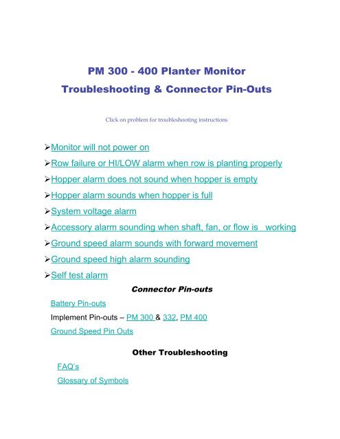
<strong>PM</strong> <strong>300</strong> - <strong>400</strong> <strong>Planter</strong> <strong>Monitor</strong><br />
<strong>Troubleshooting</strong> & <strong>Connector</strong> <strong>Pin</strong>-<strong>Outs</strong><br />
<strong>Monitor</strong> will not power on<br />
Click on problem for troubleshooting instructions<br />
Row failure or HI/LOW alarm when row is planting properly<br />
Hopper alarm does not sound when hopper is empty<br />
Hopper alarm sounds when hopper is full<br />
System voltage alarm<br />
Accessory alarm sounding when shaft, fan, or flow is working<br />
Ground speed alarm sounds with forward movement<br />
Ground speed high alarm sounding<br />
Self test alarm<br />
Battery <strong>Pin</strong>-outs<br />
<strong>Connector</strong> <strong>Pin</strong>-outs<br />
Implement <strong>Pin</strong>-outs – <strong>PM</strong> <strong>300</strong> & 332, <strong>PM</strong> <strong>400</strong><br />
Ground Speed <strong>Pin</strong> <strong>Outs</strong><br />
FAQ’s<br />
Glossary of Symbols<br />
Other <strong>Troubleshooting</strong>
<strong>Monitor</strong> Will Not Power Up<br />
PROBABLE CAUSE / CORRECTIVE ACTION<br />
1. Blown Console Fuse<br />
• Check fuse (located near battery connection). If<br />
needed, replace with 7.5 A fuse maximum. If fuse<br />
blows again, check all harnesses for pinches or<br />
breaks that may cause power short to ground.<br />
2. Poor Battery Connection<br />
• Be sure connections are clean and tight. Inspect<br />
harness for damage.<br />
3. Low Battery Voltage<br />
• Console voltage must be at least 10v. If low,<br />
recharge or replace battery.<br />
4. Defective Console<br />
Console is damaged. Contact your dealer<br />
BACK TO TROUBLESHOOTING MENU
Row Failure or HI/LOW Alarm When<br />
Row is Planting Properly<br />
PROBABLE CAUSE / CORRECTIVE ACTION<br />
Seed sensor coated with dirt<br />
• Clean sensor using a dry bottle brush<br />
Faulty sensor or harness<br />
• Trigger sensor while observing troubleshooting LED. If sensor<br />
does not have LED, swap harness connection with adjacent<br />
sensor to determine if sensor or harness is damaged. Replace<br />
sensor or harness.<br />
Defective console<br />
• Console is damaged. Contact your dealer.<br />
BACK TO TROUBLE SHOOTING MENU
Hopper Alarm Does Not Sound<br />
When Hopper is Empty<br />
PROBABLE CAUSE / CORRECTIVE ACTION<br />
Faulty sensor or harness open.<br />
• Swap harness connection with another sensor to determine if<br />
sensor or harness is damaged. Use service screen if another<br />
sensor is not available. Replace sensor or repair harness.<br />
Defective console<br />
• Console is damaged. Contact your dealer.<br />
BACK TO TROUBLE SHOOTING MENU
Hopper Alarm Sounds When<br />
Hopper is Full<br />
PROBABLE CAUSE / CORRECTIVE ACTION<br />
Faulty sensor or harness open.<br />
• Swap harness connection with another sensor to determine if<br />
sensor or harness is damaged. Use service screen if another<br />
sensor is not available. Replace sensor or repair harness.<br />
Defective console<br />
• Console is damaged. Contact your dealer.<br />
BACK TO TROUBLE SHOOTING MENU
System Voltage Alarm<br />
PROBABLE CAUSE / CORRECTIVE ACTION<br />
Low battery voltage<br />
• Console voltage must be at least 10 V. If low, recharge or replace<br />
battery.<br />
Poor battery connection<br />
• Be sure connections are clean and tight. Inspect harness for<br />
damage.<br />
Damaged harness<br />
• Check all harnesses for pinches or breaks that may cause power<br />
or 8 V-sensor power short to ground.<br />
BACK TO TROUBLE SHOOTING MENU
Accessory Alarm Sounding When<br />
Shaft, Fan, or Flow is Working<br />
PROBABLE CAUSE / CORRECTIVE ACTION<br />
Sensor failure<br />
• Shaft, fan, or flow sensor not operation. Replace defective<br />
sensors.<br />
Wrong calibration number<br />
• Sensor calibration number is incorrect. Check calibration number<br />
in accessory setup screen.<br />
Incorrect limits<br />
• Sensor limits are incorrect. Check limits in accessory setup<br />
screen.<br />
Defective console<br />
• Console is damaged. Contact your dealer.<br />
BACK TO TROUBLE SHOOTING MENU
Ground Speed Alarm Sounds With<br />
Forward Movement<br />
PROBABLE CAUSE / CORRECTIVE ACTION<br />
Ground speed sensor failure.<br />
• No ground speed sensor is detected, or planting is<br />
detected on at least one row with no ground speed.<br />
Replace faulty ground speed sensor.<br />
Console Failure<br />
• Console is damaged. Contact your dealer.<br />
BACK TO TROUBLE SHOOTING MENU
Ground Speed High Alarm<br />
Sounding<br />
PROBABLE CAUSE / CORRECTIVE ACTION<br />
Ground speed alarm set too low.<br />
• Set ground speed alarm limit higher or to zero to disable.<br />
Incorrect ground speed constant<br />
• Ground speed sensor has not been calibrated, RADAR sensor<br />
angle has changed, or incorrect sensor constant is entered. Use<br />
SPEED, AREA, DISTANCE mode to determine if speed is correct.<br />
If incorrect, recalibrate speed constant (Speed Setup Screen).<br />
BACK TO TROUBLE SHOOTING MENU
Self Test Alarm<br />
PROBABLE CAUSE / CORRECTIVE ACTION<br />
Seed sensor coated with dirt.<br />
• Clean sensor using dry bottle brush<br />
Faulty sensor or harness<br />
• Trigger sensor and observe troubleshooting LED. If<br />
sensor does not have LED, swap harness connection<br />
with adjacent sensor to determine if sensor or harness<br />
is damaged. Replace sensor or harness.<br />
Console failure<br />
• Console is damaged. Contact your dealer.<br />
BACK TO TROUBLE SHOOTING MENU
PIN LABEL<br />
Battery <strong>Pin</strong> Out<br />
Red Wire<br />
Black Wire<br />
DESCRIPTION<br />
Battery +12V<br />
Battery Ground<br />
BACK TO TROUBLE SHOOTING MENU
PIN #<br />
1<br />
2<br />
3<br />
4<br />
5<br />
6<br />
7<br />
8<br />
9<br />
10<br />
11<br />
12<br />
13<br />
14<br />
15<br />
16<br />
<strong>PM</strong> <strong>300</strong> Implement Harness<br />
<strong>PM</strong> <strong>300</strong> Implement Continued<br />
DESCRIPTION<br />
Row 1 (green)<br />
Row 2 (brown)<br />
Row 3 (blue)<br />
Row 4 (orange)<br />
Row 5 (yellow)<br />
Row 6 (violet)<br />
Row 7 (gray)<br />
Row 8 (pink)<br />
Row 9 (tan)<br />
Row 10 (wht/blk)<br />
Row 11 (red/blk)<br />
Row 12 (grn/blk)<br />
Row 13 (org/blk)<br />
Row 14 (blue/blk)<br />
Row 15 (black / white)<br />
Row 16 (red / white)<br />
17-23<br />
BACK TO TROUBLE SHOOTING MENU<br />
24<br />
25<br />
26<br />
27<br />
28<br />
29<br />
30<br />
31<br />
32<br />
33<br />
34<br />
35<br />
36<br />
37<br />
No connection<br />
8V sensor power (red)<br />
8V sensor power (red / blk/ wht)<br />
Sensor return (black)<br />
Sensor return (wht / blk / red)<br />
No connection<br />
Hopper 1 (green / white)<br />
Hopper 2 (blue / white)<br />
Shaft / fan / flow (black / red)<br />
8V power (red)<br />
12V switched power (wht/red)<br />
12V return (black)<br />
RS-232 Rx (blue / red)<br />
RS-232 Tx (red / green)<br />
Lift Switch (orange / red)
1<br />
2<br />
3<br />
4<br />
5<br />
6<br />
7<br />
8<br />
9<br />
10<br />
11<br />
12<br />
13<br />
14<br />
15<br />
16<br />
17<br />
18<br />
19<br />
<strong>PM</strong> 332 Implement Harness<br />
<strong>PM</strong> 332 Implement continued<br />
PIN #<br />
DESCRIPTION<br />
Row 1 (green)<br />
Row 2 (brown)<br />
Row 3 (blue)<br />
Row 4 (orange)<br />
Row 5 (yellow)<br />
Row 6 (violet)<br />
Row 7 (gray)<br />
Row 8 (pink)<br />
Row 9 (tan)<br />
Row 10 (wht/blk)<br />
Row 11 (red/blk)<br />
Row 12 (grn/blk)<br />
Row 13 (org/blk)<br />
Row 14 (blue/blk)<br />
Row 15 (black / white)<br />
Row 16 (red / white)<br />
Row 17 (green / white)<br />
Row 18 (blue / white)<br />
Row 19 (black red)<br />
BACK TO TROUBLE SHOOTING MENU<br />
20<br />
21<br />
22<br />
23<br />
24<br />
25<br />
26<br />
27<br />
28<br />
29<br />
30<br />
31<br />
32<br />
33<br />
34<br />
35<br />
36<br />
37<br />
Row 20 (white / red)<br />
Row 21 (orange / red)<br />
Row 22 (blue / red)<br />
Row 23 (red / green)<br />
+8V sensor power left (red)<br />
+8V snsr pwr right(red/blk/wht)<br />
Ground left (black)<br />
Ground right (wht / blk / red)<br />
Row 24 (orange)<br />
Row 25 (blk / wht / red)<br />
Row 26 (grn /blk / wht)<br />
Row 27 (org / blk/ wht)<br />
Row 28 (blue / blk / wht)<br />
Row 29 (blk / red/ green )<br />
Row 30 (wht / red / green)<br />
Row 31 (red / black / green)<br />
Row 32 (green / black / orange)<br />
Lift Switch (wht)<br />
Click here for pinouts to <strong>PM</strong> 332 Implement Accessory Harness
<strong>PM</strong> 332 Implement Accessory<br />
<strong>Pin</strong> #<br />
1<br />
2<br />
3<br />
4<br />
5<br />
6<br />
7<br />
8<br />
9<br />
Description<br />
Lift Switch (light green)<br />
Hopper #1 (brown)<br />
Hopper #2 (light blue)<br />
Frequency (orange)<br />
+8V Acc Power (yellow)<br />
+12V Acc Power (purple)<br />
Acc Return (gray)<br />
RS-232 Rx (pink)<br />
RS-232 Tx (neutral)<br />
BACK TO TROUBLE SHOOTING MENU
1<br />
2<br />
3<br />
4<br />
5<br />
6<br />
7<br />
8<br />
9<br />
10<br />
11<br />
12<br />
13<br />
14<br />
15<br />
16<br />
17<br />
18<br />
19<br />
Implement 1<br />
<strong>PM</strong> <strong>400</strong> Implement<br />
Row 1 (green)<br />
Row 2 (brown)<br />
row 3 (blue)<br />
Row 4 (orange)<br />
Row 5 (yellow)<br />
Row 6 (violet)<br />
Row 7 (gray)<br />
Row 8 (pink)<br />
Row 9 (tan)<br />
Row 10 (wht / blk)<br />
Row 11 (red / blk)<br />
Row 12 (green / blk)<br />
Row 13 (orange / blk)<br />
Row 14 (blue / blk)<br />
Row 15 (blk / wht)<br />
Row 16 (red wht)<br />
Row 17 (green / wht)<br />
Row 18 (blue / wht)<br />
Row 19 (black / red)<br />
20<br />
21<br />
22<br />
23<br />
24<br />
25<br />
26<br />
27<br />
28<br />
29<br />
30,31<br />
32<br />
33<br />
34<br />
35,36<br />
37<br />
continued<br />
BACK TO TROUBLE SHOOTING MENU<br />
Row 20 (wht / red)<br />
Row 21 (orange / red)<br />
Row 22 (blue / red)<br />
Row 23 (red / green)<br />
+8V sensor pwr left (red)<br />
+8V sensor pwr right (red)<br />
Sensor return (black)<br />
Sensor return (black)<br />
Row 24 (orange / green)<br />
Hopper 1 (wht)<br />
No connection<br />
8V power (red)<br />
No Connection<br />
Sensor return (black)<br />
No connection<br />
Lift switch (blk / wht/ red)<br />
Click here for pin outs to <strong>PM</strong><strong>400</strong> Implement 2
1<br />
2<br />
3<br />
4<br />
5<br />
6<br />
7<br />
8<br />
9<br />
10<br />
11<br />
12<br />
13-23<br />
24<br />
25<br />
26<br />
<strong>PM</strong> <strong>400</strong> Implement 2<br />
Implement 2 continued<br />
Row 25 (green)<br />
Row 26 (brown)<br />
Row 27 (blue)<br />
Row 28 (orange)<br />
Row 29 (yellow)<br />
Row 30 (violet)<br />
Row 31 (gray)<br />
Row 32 (pink)<br />
Row 33 (tan)<br />
Row 34 (wht / blk)<br />
Row 35 (red / blk)<br />
Row 36 (green / blk)<br />
No connection<br />
8V snsr pwr (red/blk/wht)<br />
8V snsr pwr (red)<br />
Snsr return (wht/blk/red)<br />
BACK TO TROUBLE SHOOTING MENU<br />
27<br />
28<br />
29<br />
30<br />
31<br />
32<br />
33<br />
34<br />
35<br />
36<br />
37<br />
Sensor return (black)<br />
No connection<br />
Hopper 1 (orange/blk)<br />
Hopper 2 (blue/blk)<br />
Shaft / fan / flow (blk/wht)<br />
8V power (red)<br />
12V switched pwr (grn/wht<br />
12V return (black)<br />
RS-232 Rx (blue/wht)<br />
RS-232 Tx (red/wht)<br />
No connection
PIN#<br />
1<br />
2<br />
3<br />
4<br />
Ground Speed<br />
Description<br />
Ground (black)<br />
Signal (green)<br />
Power (red)<br />
Sense (white)<br />
BACK TO TROUBLE SHOOTING MENU
Frequently Asked Questions<br />
<strong>PM</strong><strong>300</strong>/<strong>400</strong><br />
• Q: Can I use a R<strong>PM</strong> sensor such as a reluctance sensor for my ground speed<br />
input?<br />
A: No, the <strong>PM</strong><strong>300</strong>/<strong>400</strong> cannot read the signal produced from a reluctance sensor. It<br />
can only read a square wave/digital signal. For best results, use either our<br />
RVSII/RVSIII, iSpeed, or Hall Effect Sensor.<br />
• Q: On my <strong>PM</strong><strong>400</strong>, how many rows can I put on J1 by itself?<br />
A: J1 can take 24 row inputs. Any more, and you’ll have to put extra rows on J2.<br />
However, the <strong>PM</strong><strong>400</strong> can only monitor 48 rows at a time. If you want to monitor<br />
more rows, try our Seed Manager SE for population or DjASM II for no population.<br />
The <strong>PM</strong><strong>300</strong> can take 16 rows on J1.<br />
• Q: My <strong>PM</strong><strong>300</strong> / <strong>400</strong> won’t stop counting acres and is only showing speed.<br />
A: You could be in Speed and Area mode. Push Operate to show normal operation.<br />
Speed and Area mode should not be used unless you are using the monitor for a<br />
non-planting operation, cultivating, plowing, disking, etc.<br />
• Q: Is there a quick way to clear the acres off the monitor?<br />
A: Yes, use the up and down arrows next to the display to make sure the acre<br />
accumulator is at the top of the screen. Then, push and hold Escape for three<br />
seconds, and it will clear.<br />
• Q: My ground speed sensor has malfunctioned. Can I put a manual speed in?<br />
A: Yes, push the ground speed button, scroll down to the manual speed, and enter<br />
a speed you typically run. Keep in mind, you need to maintain the entered speed<br />
you enter to maintain proper acre counter, population, and spacing. If you lose<br />
speed as you plant, an alarm will sound and a tractor with an X through it will be<br />
displayed. When this happens, at the bottom of the screen the number 00.0 will be<br />
a highlighted. Use the up and down arrow keys to the right of the display to change<br />
to your normal planting speed, and then press enter. This will automatically put you<br />
into a manual mode. Once this is completed, press the operate key and start<br />
planting.<br />
Other frequently asked questions<br />
BACK TO TROUBLE SHOOTING MENU
Frequently Asked Questions<br />
<strong>PM</strong><strong>300</strong>/<strong>400</strong> (continued)<br />
• Q: Is there any way to adjust the brightness of the screen to make it is easier<br />
to read?<br />
A: Yes, press the display and service button. Using the up and down arrow keys to<br />
the right of the display scroll down to the light bulb, press enter, and use the up and<br />
down buttons to adjust brightness.<br />
• Q: Is there any way to change the volume of the alarm?<br />
A: Yes, press the Display and Service button. Using the up and down arrow keys<br />
scroll down to the speaker, press Enter, and use the up/down arrows to adjust the<br />
volume. Once you have found a tolerable level, press Enter to save your settings.<br />
Then press the Operate key to resume planting.<br />
• Q: Can I change the font size on the display?<br />
A: Yes, press the Display and Service button. Using the up/down arrow keys, scroll<br />
down to the magnifying glass, and press Enter. When you found the font size you<br />
like, press Enter to save, then press Operate to resume planting.<br />
• Q: Can I use the <strong>PM</strong><strong>300</strong> / <strong>400</strong> to count acres only?<br />
A: Yes, push the Speed and Area button to access one of the different counters.<br />
There are four different counters to choose from, and there will be a stop and start<br />
function for each counter. After selecting the counter you want, use the up/down<br />
arrow keys to the right of the display, and press Enter to stop/start the selected acre<br />
counter. To clear all totals, press the Clear button.<br />
• Q: Can the <strong>PM</strong><strong>300</strong> / <strong>400</strong> monitor fertilizer drops as well as seed drops?<br />
A: Yes, press the Accuracy setup button. Using the up/down arrow keys to the right<br />
of the display, select what you want the monitor to do and calibrate accordingly.<br />
The <strong>PM</strong> <strong>300</strong>/<strong>400</strong> can also monitor a shaft and fan sensor<br />
BACK TO TROUBLE SHOOTING MENU
Glossary of Symbols<br />
Alarm All Rows<br />
Failed<br />
Area Per<br />
Hour<br />
Backlight Configuration English<br />
to Metric<br />
Average<br />
Population<br />
Average<br />
Spacing<br />
Fan Field Area 1<br />
Field Area 2 Flow Graphic Text HiLo Hopper Low<br />
Minimum Average<br />
Maximum Population<br />
<strong>Planter</strong><br />
Lifted<br />
Minimum Average<br />
Maximum Seeds per<br />
Distance<br />
Population<br />
Adjust<br />
Minimum Average<br />
Maximum Spacing<br />
Population<br />
Row Scan<br />
Symbols Continued<br />
No Flow No Speed<br />
BACK TO TROUBLE SHOOTING MENU<br />
Reset Response<br />
Rate
Glossary of Symbols<br />
(Continued)<br />
Save<br />
Password<br />
Spacing Row<br />
Scan<br />
Security Seeds Per<br />
Distance<br />
Seeds Per<br />
Distance Row<br />
Scan<br />
Shaft<br />
Speed Start Stop Total Area Warning<br />
BACK TO TROUBLE SHOOTING MENU