PVC3000™ Proportional Hydraulic Control Valve - DICKEY-john ...
PVC3000™ Proportional Hydraulic Control Valve - DICKEY-john ...
PVC3000™ Proportional Hydraulic Control Valve - DICKEY-john ...

Create successful ePaper yourself
Turn your PDF publications into a flip-book with our unique Google optimized e-Paper software.
INSTALLATION INSTRUCTIONS<br />
11001-1454-200710<br />
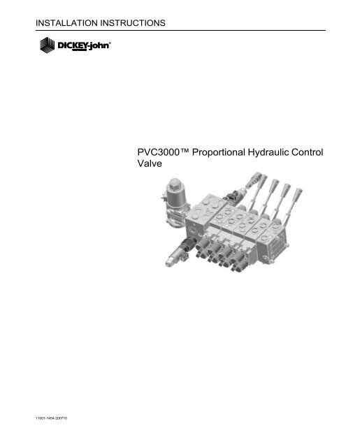
PVC3000 <strong>Proportional</strong> <strong>Hydraulic</strong> <strong>Control</strong><br />
<strong>Valve</strong>
INSTALLATION INSTRUCTIONS<br />
11001-1454-200710
TABLE OF CONTENTS<br />
PVC3000 <strong>Valve</strong><br />
11001-1454-200710<br />
Introduction .......................................................................................................... 1<br />
Features............................................................................................................................. 1<br />
Specifications..................................................................................................................... 2<br />
Electrical............................................................................................................................................ 2<br />
Base Manifold ................................................................................................................................... 2<br />
Plow and Hoist <strong>Control</strong> Modules ....................................................................................................... 3<br />
<strong>Valve</strong> Identification............................................................................................................. 4<br />
Port Connections.............................................................................................................................. 4<br />
Installation.......................................................................................................................... 5<br />
System Diagram ................................................................................................................ 6<br />
<strong>Hydraulic</strong> Connections........................................................................................ 7<br />
Plow and Hoist Module Connections ................................................................................. 8<br />
Manual Override................................................................................................................................ 9<br />
Frequently Asked Questions ............................................................................ 11<br />
Service Parts ...................................................................................................... 13<br />
End Cap .......................................................................................................................................... 13<br />
Basic Module................................................................................................................................... 13<br />
Mechanical Lever ............................................................................................................................ 13<br />
Electrical Coils................................................................................................................................. 13<br />
Spools for Basic Module ................................................................................................................. 14<br />
Bolt Kit for <strong>Valve</strong> Sections............................................................................................................... 14<br />
Port Relief <strong>Valve</strong>s for Basic Modules .............................................................................................. 15<br />
Base Manifold Parts......................................................................................................... 16<br />
Conveyor, Spinner, Pre-wet <strong>Proportional</strong> <strong>Valve</strong>s............................................................................ 16<br />
Bi-directional <strong>Valve</strong> for Conveyor.................................................................................................... 16<br />
Check <strong>Valve</strong> for Base Manifold ....................................................................................................... 16<br />
Warranty ..............................................................................................................17<br />
i
TABLE OF CONTENTS<br />
ii<br />
PVC3000 <strong>Valve</strong><br />
11001-1454-200710
INSTALLATION INSTRUCTIONS<br />
PVC3000 <strong>Valve</strong><br />
11001-1454-200710<br />
INTRODUCTION<br />
The PVC3000 <strong>Valve</strong> is a complete central proportional hydraulic control<br />
system for salt spreading and/or hydraulic plow control applications. The<br />
system is compatible with load sense and fixed displacement hydraulic<br />
systems.<br />
Figure 1<br />
PVC3000<br />
FEATURES<br />
• Open-Center and Closed-Center technology<br />
• Each plow and hoist module is dual control (up/down per module, left/<br />
right per module)<br />
• <strong>Hydraulic</strong> flow range for each hoist and plow module ranges from 1-32<br />
gallons per minute<br />
• Mechanical levers for manual override<br />
• Optional pressure relief valve add-on for use as a hydraulic overload<br />
relief through the valve<br />
• Environmentally sealed<br />
• Top side connections for ease of installation<br />
INTRODUCTION / 1
INSTALLATION INSTRUCTIONS<br />
2 / INTRODUCTION<br />
SPECIFICATIONS<br />
ELECTRICAL<br />
Actuation: Pulse Width Modulated<br />
<strong>Control</strong> Signal: 0-750 mA (24V), 0-1500 mA (12V)<br />
Response Time: 150-200 ms<br />
Ambient Temperature: -30 to +80 degrees C<br />
Pilot Pressure: 25 bar (PVH)<br />
No spool position feedback control<br />
2A, 100-400 Hz pulse width modulated control signals<br />
Deutsch connectors<br />
12V proportional coils<br />
BASE MANIFOLD<br />
The Base Manifold controls spreader, spinner, and prewet functions.<br />
Spreader<br />
• <strong>Proportional</strong> operation<br />
• SAE 10 o-ring Boss port<br />
• Pressure compensated<br />
• Up to 20 gallons per minute<br />
• Optional reversible conveyor<br />
Spinner<br />
• <strong>Proportional</strong> operation<br />
• SAE 8 o-ring Boss port<br />
• Pressure compensated<br />
• Up to 8 gallons per minute<br />
Pre-Wet<br />
• <strong>Proportional</strong> operation<br />
• SAE 8 o-ring Boss port<br />
• Up to 6 gallons per minute<br />
• Pressure compensated<br />
PVC3000 <strong>Valve</strong><br />
11001-1454-200710
INSTALLATION INSTRUCTIONS<br />
PVC3000 <strong>Valve</strong><br />
11001-1454-200710<br />
PLOW AND HOIST CONTROL MODULES<br />
Each module performs two hydraulic functions (up/down or left/right).<br />
Therefore, to perform all functions (up/down/left/right) two modules are<br />
required.<br />
Hoist SAE<br />
• <strong>Proportional</strong> operation (up/down per module) (left/right per module)<br />
• SAE 10 o-ring Boss ports<br />
• <strong>Valve</strong> section capacity 32 gallons per minute with proportional coil<br />
Front Plow<br />
• <strong>Proportional</strong> operation (up/down per module) (left/right per module)<br />
• SAE 10 o-ring Boss ports<br />
• 10 gallons per minute capacity (spool limited) valve; section capacity<br />
32 gallons per minute<br />
• Spool limiters standard for precise flow limitation<br />
• Section with proportional coil<br />
Side Wing<br />
• <strong>Proportional</strong> operation (up/down/left/right)<br />
• SAE 19 o-ring Boss ports<br />
• 17 gallons per minute capacity (spool limited) valve; section capacity<br />
32 gallons per minute<br />
• Spool limiters standard for precise flow limitation<br />
• Section with proportional coil<br />
• Automatic safety retraction<br />
Underbody Scraper<br />
• SAE 10 o-ring Boss ports<br />
• 17 gallons per minute capacity (spool limited) valve; section capacity<br />
32 gallons per minute<br />
• Spool limiters standard for precise flow limitation<br />
• Section with proportional coil<br />
PWM Coil Parameters for Plow and Hoist Modules<br />
• Current: 12 VDC (1-1500 ma)<br />
• Pressure <strong>Control</strong>: 72-217 psi<br />
INTRODUCTION / 3
INSTALLATION INSTRUCTIONS<br />
Figure 2<br />
<strong>Valve</strong> Identification<br />
End Cap<br />
Load Sense<br />
PVG<br />
Spool<br />
4 / INTRODUCTION<br />
Bolt kit<br />
VALVE IDENTIFICATION<br />
Port<br />
Relief<br />
<strong>Valve</strong> for<br />
Pre-Wet<br />
Manual<br />
Override<br />
Lever<br />
Electrical Coil<br />
Activation<br />
Coil<br />
PORT CONNECTIONS<br />
Plow and Hoist<br />
<strong>Control</strong><br />
Module<br />
Cavity<br />
Plug<br />
Plow and Hoist<br />
<strong>Control</strong><br />
Module<br />
Base<br />
Manifold<br />
<strong>Valve</strong> for<br />
Spinner<br />
Plow and Hoist<br />
<strong>Control</strong><br />
Module<br />
Port Connections Location Size<br />
Pressure Inlet (P) and Tank<br />
Return (T)<br />
End Cap SAE-12<br />
Port A and B Plow and Hoist Modules SAE-10<br />
Conveyor, Conveyor A,<br />
Conveyor B<br />
Base Manifold SAE-10<br />
Prewet and Spinner Base Manifold SAE-8<br />
Load Sense A and B (LSa/LSb) End Cap SAE-5<br />
Refer to (Figure 6) for illustration depicting port locations.<br />
<strong>Valve</strong> for<br />
Spreader<br />
Bidirectional<br />
or Auger Reversing<br />
<strong>Valve</strong><br />
PVC3000 <strong>Valve</strong><br />
11001-1454-200710
INSTALLATION INSTRUCTIONS<br />
PVC3000 <strong>Valve</strong><br />
11001-1454-200710<br />
INSTALLATION<br />
The valve is secured to the mounting location with user-supplied bolts. Two<br />
mounting holes are located on the Base Manifold and the End Cap.<br />
To Mount <strong>Valve</strong>:<br />
1. Position the valve in the desired mounting location.<br />
2. Mark position to drill holes.<br />
3. Attach valve with user-supplied 4x, 5/16-18 NC bolts.<br />
Figure 3<br />
Mounting Holes<br />
Mounting<br />
Holes<br />
Figure 4<br />
Mounting Dimensions Table<br />
L1<br />
L<br />
Mounting<br />
Holes<br />
Reference Dimension Table for L1 and L dimensions<br />
based on number of modules used.<br />
(Inches)<br />
1 2 3 4<br />
# of Modules<br />
5 6 7 8 9<br />
Dimension of (L) with<br />
Uni-directional <strong>Valve</strong><br />
7.98 9.87 11.76 13.65 15.54 17.43 19.32 21.21 23.10<br />
Dimension of (L) with<br />
Bi-directional <strong>Valve</strong><br />
11.13 13.02 14.91 16.80 18.69 20.58 22.47 24.36 26.25<br />
Dimension of (L1) 3.54 5.43 7.32 9.21 11.10 12.99 14.88 16.77 18.66<br />
INTRODUCTION / 5
INSTALLATION INSTRUCTIONS<br />
Figure 5<br />
System Diagram<br />
1/2” CASE DRAIN<br />
2” SUCTION HOSE<br />
6 / INTRODUCTION<br />
3/4” PRESSURE HOSE<br />
1/4” LOAD SENSE (Closed Center only)<br />
CUSHION<br />
VALVE<br />
PLOW<br />
CYLINDER<br />
SYSTEM DIAGRAM<br />
HYDRAULIC<br />
RESERVOIR<br />
3/4” HOSE<br />
HOIST CYLINDER<br />
3/4” RETURN<br />
1/2” HOSE<br />
1/4” VALVE OPEN<br />
7GPM<br />
AUGER MOTOR<br />
1/2” SPINNER LINE<br />
3/4” RETURN<br />
SPINNER<br />
PREWET<br />
PVC3000 <strong>Valve</strong><br />
11001-1454-200710
INSTALLATION INSTRUCTIONS<br />
Figure 6<br />
<strong>Valve</strong> Connections<br />
PVC3000 <strong>Valve</strong><br />
11001-1454-200710<br />
Optional<br />
Auger Reversing<br />
<strong>Valve</strong><br />
To Main<br />
<strong>Hydraulic</strong> Motor<br />
Conveyor A<br />
Bi-directional<br />
Conveyor B<br />
Bi-directional<br />
HYDRAULIC CONNECTIONS<br />
Spinner<br />
Pre-Wet<br />
1. Connect the pressure line from the hydraulic pump to the pressure inlet<br />
of the valve (P).<br />
2. Connect the pressure line from the tank return to the pressure inlet of<br />
the valve (T).<br />
3. For Closed Center hydraulics, remove the cap from the Load Sense<br />
port and connect the Load Sense line from the pump to the load sense<br />
port located on the valve end cap.<br />
4. If required, remove cap and connect optional Auger Reversing <strong>Valve</strong> to<br />
run conveyor in bi-directional applications.<br />
Conveyor<br />
Uni-directional<br />
Check<br />
<strong>Valve</strong><br />
Dump Body<br />
Module<br />
Front Plow<br />
Up/Down<br />
Module<br />
Front Plow<br />
Left/Right<br />
Module<br />
Mechanical<br />
Electrical<br />
Connections<br />
“B” coil<br />
“A” coil<br />
“A”<br />
port<br />
“B”<br />
port<br />
Underbody<br />
Scraper<br />
Module<br />
Main<br />
Relief<br />
Pressure<br />
Port “P”<br />
Tank<br />
Return “T”<br />
Load<br />
Sense<br />
Pressure to<br />
<strong>Hydraulic</strong> Pump<br />
Pressure<br />
to Tank<br />
Return<br />
HYDRAULIC CONNECTIONS / 7
INSTALLATION INSTRUCTIONS<br />
NOTE: Recommended electrical and<br />
hydraulic configuration is to<br />
connect the Up and Left<br />
functions to the “A” Coil -<br />
“A” Port; and the Down and<br />
Right functions to the “B”<br />
Coil - “B” Port.<br />
8 / HYDRAULIC CONNECTIONS<br />
PLOW AND HOIST MODULE CONNECTIONS<br />
Plow and Hoist modules are positioned and labeled on the valve in the<br />
following order:<br />
1. Dump Body (Up/Down)<br />
2. Dump Body (Left/Right)<br />
3. Front Plow (Up/Down)<br />
4. Front Plow (Left/Right)<br />
5. Side Wing (Up/Down)<br />
6. Side Wing (Left/Right)<br />
7. Underbody Scraper (Up/Down)<br />
8. Underbody Scraper (Left/Right)<br />
Connecting Harnesses to <strong>Valve</strong>:<br />
1. Route all material spreader and plow control harnesses (Plow, Dump<br />
Body, Wing Plow, and Underbody Scraper) from the Main Cab harness<br />
to the hydraulic valve.<br />
2. Attach connectors from the material spreader control harness to the<br />
conveyor, spinner, prewet coils on the hydraulic valve.<br />
3. Attach connectors from the plow control harness to the “A” and “B” coil<br />
on the hydraulic valve.<br />
4. “B” Coil on the hydraulic valve.<br />
Electrical and hydraulic lines MUST be connected so that the “A” coil<br />
energizes flow to the “A” port and the “B” coil energizes flow to the “B” port<br />
to activate the function correctly.<br />
Figure 7<br />
Electrical and <strong>Hydraulic</strong> Line Connections<br />
Main<br />
Relief<br />
Pressure (P)<br />
Port Tank Return (T)<br />
Port<br />
Load Sense<br />
Relief “A”<br />
“B” Coil<br />
Flow to “B”<br />
Port<br />
“A” Coil<br />
Flow to “A”<br />
Port<br />
Load Sense<br />
Relief “B”<br />
PVC3000 <strong>Valve</strong><br />
11001-1454-200710
INSTALLATION INSTRUCTIONS<br />
PVC3000 <strong>Valve</strong><br />
11001-1454-200710<br />
Ensure all electrical connections and hydraulic lines are properly<br />
connected before initial operation. Improper connections can<br />
result in an unexpected function causing injury to persons or<br />
equipment.<br />
MANUAL OVERRIDE<br />
External levers attached to individual plow and hoist modules mechanically<br />
operate the dual functions.<br />
Figure 8<br />
Manual Override<br />
Pull Handle to<br />
energize Port “B”<br />
and move position<br />
to “DOWN” or “RIGHT”<br />
Push Handle to<br />
energize Port “A”<br />
and move position<br />
to “UP” or “LEFT”<br />
HYDRAULIC CONNECTIONS / 9
INSTALLATION INSTRUCTIONS<br />
10 / HYDRAULIC CONNECTIONS<br />
PVC3000 <strong>Valve</strong><br />
11001-1454-200710
INSTALLATION INSTRUCTIONS<br />
PVC3000 <strong>Valve</strong><br />
11001-1454-200710<br />
FREQUENTLY ASKED QUESTIONS<br />
QUESTION ANSWER<br />
1. What information is required to order<br />
a valve?<br />
2. What is the maximum number of<br />
sections allowed.<br />
3. Is this valve compatible with a 24V<br />
system?<br />
4. Can the sections be used for<br />
different applications without a<br />
conveyer/spinner?<br />
5. Can this valve perform other<br />
functions besides ice control.<br />
6. How many add-on sections are<br />
required for plow and hoist?<br />
1. <strong>Valve</strong> functionality (spinner, plow, scraper, etc).<br />
2. GPM’s for each section including conveyer,<br />
spinner, prewet.<br />
Up to 16 sections.<br />
Yes.<br />
Yes. The valve will have two end caps instead of<br />
the conveyer/spinner block.<br />
Yes, this valve can perform any hydraulic function.<br />
3 sections (1 for hoist and 2 for plow).<br />
7. How can the valve be mounted? The valve can be mounted vertically and<br />
horizontally.<br />
8. Can extra sections be added after<br />
installation?<br />
9. Can the valve function without a<br />
controller?<br />
10. Can an auger reverser be added<br />
after installation?<br />
11. Why does the plow function not<br />
move?<br />
Yes, the valve can be taken apart and sections<br />
added at a later time.<br />
Yes, the valve can be controlled using the manual<br />
levers.<br />
Yes.<br />
Electrical valve or cylinder problem has occurred.<br />
Use manual levers to override system.<br />
FREQUENTLY ASKED QUESTIONS / 11
INSTALLATION INSTRUCTIONS<br />
12 / FREQUENTLY ASKED QUESTIONS<br />
PVC3000 <strong>Valve</strong><br />
11001-1454-200710
INSTALLATION INSTRUCTIONS<br />
PVC3000 <strong>Valve</strong><br />
11001-1454-200710<br />
SERVICE PARTS<br />
END CAP<br />
Part<br />
Number<br />
Contact Dickey-<strong>john</strong> Technical Support at 1-800-637-3302 to order End<br />
Cap parts.<br />
BASIC MODULE<br />
Description<br />
tbd End Cap Module (open center circuit)<br />
tbd End Cap Module (closed center circuit)<br />
tbd Seals between Basic Module and End Cap Module<br />
tbd Seals<br />
Part<br />
Number Description<br />
tbd Module with check valve but not prepared for shock valves<br />
tbd Module with check valve and prepared for shock valves<br />
tbd Module with compensator valve and load sensing relief valve but not<br />
prepared for shock valve (primarily for float function)<br />
tbd Seals between Basic Module<br />
tbd Shock valve o-ring<br />
Contact Dickey-<strong>john</strong> Technical Support at 1-800-637-3302 to order<br />
Basic Module parts.<br />
MECHANICAL LEVER<br />
Part<br />
Number Description<br />
467094000 Mechanical Lever<br />
467094005 Seals<br />
Torque to fix bolts from Handle to Basic Module<br />
ELECTRICAL COILS<br />
Part<br />
Number<br />
Description<br />
467094010 Coils<br />
467094015 Seals<br />
Torque to fix bolts from Coil to Basic Module 70 +/- 4.5 lb-in<br />
SERVICE PARTS / 13
INSTALLATION INSTRUCTIONS<br />
Contact Dickey-<strong>john</strong> Technical<br />
Support at 1-800-637-3302 to order<br />
Basic Module Spools.<br />
14 / SERVICE PARTS<br />
SPOOLS FOR BASIC MODULE<br />
Part<br />
Number Description<br />
tbd Cylinder Spool (Double Acting)<br />
1.3 GPM<br />
2.6 GPM<br />
6.6 GPM<br />
10.6 GPM<br />
17.2 GPM<br />
26.4 GPM<br />
34.3 GPM<br />
tbd Single Acting Spool<br />
1.3 GPM<br />
2.6 GPM<br />
6.6 GPM<br />
10.6 GPM<br />
17.2 GPM<br />
26.4 GPM<br />
tbd Motor Spool (Double Acting)<br />
1.3 GPM<br />
2.6 GPM<br />
6.6 GPM<br />
10.6 GPM<br />
17.2 GPM<br />
26.4 GPM<br />
34.3 GPM<br />
tbd Float Spool (used with 157B6603 or 157B6633<br />
Basic Module)<br />
2.6 GPM<br />
6.6 GPM<br />
10.6 GPM<br />
17.2 GPM<br />
26.4 GPM<br />
BOLT KIT FOR VALVE SECTIONS<br />
Part<br />
Number<br />
Description<br />
467094020 PVG <strong>Valve</strong> Bolt Kit (2 sections) 20 lbf-ft<br />
467094025 PVG <strong>Valve</strong> Bolt Kit (3 sections) 20 lbf-ft<br />
467094030 PVG <strong>Valve</strong> Bolt Kit (4 sections) 20 lbf-ft<br />
467094035 PVG <strong>Valve</strong> Bolt Kit (5 sections) 20 lbf-ft<br />
467094040 PVG <strong>Valve</strong> Bolt Kit (6 sections) 20 lbf-ft<br />
467094045 PVG <strong>Valve</strong> Bolt Kit (7 sections) 20 lbf-ft<br />
467094050 PVG <strong>Valve</strong> Bolt Kit (8 sections) 20 lbf-ft<br />
467094055 PVG <strong>Valve</strong> Bolt Kit (9 sections) 20 lbf-ft<br />
467094060 PVG <strong>Valve</strong> Bolt Kit (10 sections) 20 lbf-ft<br />
PVC3000 <strong>Valve</strong><br />
11001-1454-200710
INSTALLATION INSTRUCTIONS<br />
PVC3000 <strong>Valve</strong><br />
11001-1454-200710<br />
PORT RELIEF VALVES FOR BASIC MODULES<br />
Part<br />
Number Description<br />
tbd Shock valve adjusted at 460 psi code “A”<br />
tbd Shock valve adjusted at 725 psi code “B”<br />
tbd Shock valve adjusted at 914 psi code “C”<br />
tbd Shock valve adjusted at 1160 psi code “D”<br />
tbd Shock valve adjusted at 1450 psi code “E”<br />
tbd Shock valve adjusted at 1813 psi code “F”<br />
tbd Shock valve adjusted at 2031 psi code “G”<br />
tbd Shock valve adjusted at 2175 psi code “H”<br />
tbd Shock valve adjusted at 2320 psi code “I”<br />
tbd Shock valve adjusted at 2538 psi code “J”<br />
tbd Shock valve adjusted at 2755 psi code “K”<br />
tbd Shock valve adjusted at 3045 psi ocde “L”<br />
tbd Shock valve adjusted at 3335 psi code “M”<br />
tbd Shock valve adjusted at 3480 psi code “N”<br />
tbd Shock valve adjusted at 3625 psi code “O”<br />
tbd Shock valve adjusted at 3845 psi code “P”<br />
tbd Shock valve adjusted at 4061 psi code “Q”<br />
tbd Shock valve adjusted at 4351 psi code “R”<br />
tbd Shock valve adjusted at 4641 psi code “S”<br />
tbd Shock valve adjusted at 5075 psi code “T”<br />
tbd Anti-cavitation valve<br />
Contact Dickey-<strong>john</strong> Technical Support at 1-800-637-3302 to order Port<br />
Relief <strong>Valve</strong>s.<br />
SERVICE PARTS / 15
INSTALLATION INSTRUCTIONS<br />
16 / SERVICE PARTS<br />
BASE MANIFOLD PARTS<br />
CONVEYOR, SPINNER, PRE-WET PROPORTIONAL<br />
VALVES<br />
Part<br />
Number<br />
Description<br />
467094065 Conveyor <strong>Proportional</strong> <strong>Valve</strong><br />
467094070 Spinner <strong>Proportional</strong> <strong>Valve</strong><br />
467094075 Pre-Wet <strong>Proportional</strong> <strong>Valve</strong><br />
467094080 Cavity plug for valve without Pre-Wet option<br />
467094085 Coil<br />
BI-DIRECTIONAL VALVE FOR CONVEYOR<br />
Part<br />
Number<br />
Description<br />
467094090 Directional <strong>Valve</strong><br />
467094095 Mounting bolts set<br />
467094100 Coils<br />
467094105 Seals<br />
467094110 Cover (if bi-directional valve is not used)<br />
CHECK VALVE FOR BASE MANIFOLD<br />
Part<br />
Number<br />
Description<br />
467094115 Check <strong>Valve</strong><br />
PVC3000 <strong>Valve</strong><br />
11001-1454-200710
Dealers have the responsibility of calling to the attention of their customers the following<br />
warranty prior to acceptance of an order from their customer for any <strong>DICKEY</strong>-<strong>john</strong> product.<br />
<strong>DICKEY</strong>-<strong>john</strong>® WARRANTY<br />
<strong>DICKEY</strong>-<strong>john</strong> warrants to the original purchaser for use that, if any part of the product<br />
proves to be defective in material or workmanship within one year from date of original<br />
installation, and is returned to <strong>DICKEY</strong>-<strong>john</strong> within 30 days after such defect is discovered,<br />
<strong>DICKEY</strong>-<strong>john</strong> will (at our option) either replace or repair said part. This warranty does not apply<br />
to damage resulting from misuse, neglect, accident, or improper installation or maintenance; any<br />
expenses or liability for repairs made by outside parties without <strong>DICKEY</strong>-<strong>john</strong>’s written consent;<br />
damage to any associated equipment; or lost profits or special damages. Said part will not be<br />
considered defective if it substantially fulfills the performance expectations. THE FOREGOING<br />
WARRANTY IS EXCLUSIVE AND IN LIEU OF ALL OTHER WARRANTIES OF<br />
MERCHANTABILITY, FITNESS FOR PURPOSE, AND OF ANY OTHER TYPE, WHETHER<br />
EXPRESS OR IMPLIED. <strong>DICKEY</strong>-<strong>john</strong> neither assumes nor authorizes anyone to assume for it<br />
any other obligation or liability in connection with said part and will not be liable for<br />
consequential damages. Purchaser accepts these terms and warranty limitations unless the<br />
product is returned within fifteen days for full refund of purchase price.<br />
For <strong>DICKEY</strong>- <strong>john</strong> Service Department, call<br />
1-800-637-3302 in either the U.S.A. or Canada<br />
Headquarters:<br />
5200 Dickey-<strong>john</strong> Road, Auburn, IL 62615<br />
TEL: 217-438-3371, FAX: 217-438-6012, WEB: www.dickey-<strong>john</strong>.com<br />
Europe:<br />
<strong>DICKEY</strong>-<strong>john</strong> Europe S.A.S, 165, boulevard de Valmy, 92700 – Columbes – France<br />
TEL: 33 (0) 1 41 19 21 80, FAX: 33 (0) 1 47 86 00 07 WEB: www.dickey-<strong>john</strong>.eu<br />
Copyright 2007 <strong>DICKEY</strong>-<strong>john</strong> Corporation<br />
Specifications subject to change without notice.