RPD Manual 11 - Removable Prosthodontics - Dalhousie University
RPD Manual 11 - Removable Prosthodontics - Dalhousie University
RPD Manual 11 - Removable Prosthodontics - Dalhousie University

You also want an ePaper? Increase the reach of your titles
YUMPU automatically turns print PDFs into web optimized ePapers that Google loves.
<strong>Removable</strong> Partial<br />
Denture <strong>Manual</strong><br />
Robert W. Loney, DMD, MS<br />
20<strong>11</strong>
<strong>Removable</strong> Partial<br />
Denture <strong>Manual</strong><br />
Robert W. Loney, DMD, MS<br />
20<strong>11</strong>
Table of Contents<br />
Table of Contents - i<br />
Introduction to <strong>Removable</strong> Partial Dentures ............................................................................. 1<br />
Alternatives to <strong>RPD</strong>'s .................................................................................................................. 1<br />
Indications for <strong>RPD</strong>'s .................................................................................................................. 1<br />
Treatment Objectives .................................................................................................................. 1<br />
Components of a Partial Denture ................................................................................................ 3<br />
Classification .............................................................................................................................. 4<br />
Kennedy Classification ....................................................................................................... 4<br />
Applegate's Rules for Applying the Kennedy Classification ............................................. 5<br />
Anatomy Tour for Complete and Partial Dentures ................................................................... 6<br />
Irreversible Hydrocolloid Preliminary Impressions ............................................................... <strong>11</strong><br />
Making the impression ............................................................................................................. <strong>11</strong><br />
Evaluating Irreversible Hydrocolloid Impressions ................................................................... 12<br />
Pouring a Model ....................................................................................................................... 12<br />
Two-Pour Technique ................................................................................................................ 12<br />
Trimming .................................................................................................................................. 13<br />
Surveying, Path of Insertion, Guiding Planes .......................................................................... 14<br />
Parts of a Surveyor: .................................................................................................................. 15<br />
Selecting the Path of Insertion of a <strong>Removable</strong> Partial Denture .............................................. 16<br />
The Optimal Path of Insertion .................................................................................................. 17<br />
Selection and Preparation of Guiding Planes: .......................................................................... 20<br />
The Effects of Guiding Planes on Retention and Stability ....................................................... 21<br />
Alteration of Other Axial Contours .......................................................................................... 22<br />
Summary of <strong>Removable</strong> Partial Denture Abutment Modifications ......................................... 23<br />
Rests and Rest Seats ................................................................................................................... 24<br />
Functions of Rests ..................................................................................................................... 24<br />
Preparation of Rest Seats .......................................................................................................... 25<br />
Rest Seat Form .......................................................................................................................... 25<br />
Occlusal Rest Seats ............................................................................................................... 25<br />
Lingual Rest Seats ................................................................................................................ 27<br />
Composite Buildups for Cingulum Rests: ............................................................................ 30<br />
Round Lingual Rest Seat Form ............................................................................................. 31<br />
Incisal Rests .......................................................................................................................... 31
Table of Contents - ii<br />
Major Connectors ....................................................................................................................... 32<br />
Functions of a Major Connector ............................................................................................... 32<br />
Requirements of a Major Connector ......................................................................................... 32<br />
I. Mandibular Major Connectors ............................................................................................ 33<br />
Lingual Bar ....................................................................................................................... 33<br />
Lingual Plate (Linguoplate) .............................................................................................. 34<br />
Continuous Bar Retainer (Kennedy Bar, Double Lingual Bar) ........................................ 35<br />
Labial Bar ......................................................................................................................... 35<br />
II. Maxillary Major Connectors .............................................................................................. 35<br />
Anterior-Posterior Palatal Strap ........................................................................................ 35<br />
Full Palatal Plate ............................................................................................................... 36<br />
Single Palatal Strap .......................................................................................................... 36<br />
Anterior Palatal Plate ....................................................................................................... 37<br />
Minor Connectors ....................................................................................................................... 38<br />
Functions ................................................................................................................................... 38<br />
Basic Types of Minor Connectors: ........................................................................................... 38<br />
Gridwork Design ...................................................................................................................... 41<br />
Direct and Indirect Retainers .................................................................................................... 43<br />
Extra-Coronal Direct Retainers ................................................................................................ 43<br />
Requirements of Direct Retainers ............................................................................................. 44<br />
Factors affecting the magnitude of retention ............................................................................ 44<br />
Direct Retainers For Tooth-Borne <strong>RPD</strong>’s ................................................................................ 46<br />
1. Circumferential (Circle or Akers) clasp ........................................................................... 46<br />
2. Ring clasp ........................................................................................................................ 47<br />
3. Embrasure (Double Akers) Clasp .................................................................................... 47<br />
4. "C" clasp (Hair-pin or Reverse action) ............................................................................ 48<br />
Direct Retainers For Tooth and Tissue Borne <strong>RPD</strong>'s ............................................................... 49<br />
1. Bar Clasps ........................................................................................................................ 49<br />
2. The R-P-I Clasp ............................................................................................................... 50<br />
3. Combination Clasp .......................................................................................................... 52<br />
4. RPA Clasp ...................................................................................................................... 52<br />
The Distal Rest Concept ....................................................................................................... 52<br />
Direct Retainer Selection .......................................................................................................... 55<br />
Indirect Retainers ...................................................................................................................... 56<br />
Denture Bases and Replacement Denture Teeth ..................................................................... 59<br />
Functions ................................................................................................................................... 59<br />
Materials ................................................................................................................................... 59<br />
Flange Extension .................................................................................................................. 60<br />
Acrylic Resin Finish Lines ................................................................................................... 61<br />
Partial Denture Replacement Teeth ...................................................................................... 61
Table of Contents -iii<br />
Principles of Partial Denture Design ......................................................................................... 63<br />
Denture Bases ........................................................................................................................... 64<br />
Direct Retainers ........................................................................................................................ 64<br />
Number of Direct Retainers ...................................................................................................... 66<br />
Indirect Retainers ...................................................................................................................... 66<br />
Major Connectors ..................................................................................................................... 66<br />
Distal Extension Case Considerations ...................................................................................... 67<br />
General Considerations ............................................................................................................. 68<br />
Drawing the Design .................................................................................................................. 66<br />
Design Session ............................................................................................................................. 71<br />
Clinical Protocol for <strong>Removable</strong> Partial Dentures .................................................................. 79<br />
Diagnosis & Treatment Planning .............................................................................................. 79<br />
Final Impressions for Partial Dentures ..................................................................................... 80<br />
Framework Impressions ........................................................................................................ 80<br />
Evaluating the Impression ........................................................................................................ 82<br />
<strong>Removable</strong> Partial Denture Framework Fabrication ............................................................. 84<br />
Partial Denture Framework Adjustment ................................................................................. 84<br />
Pre-clinical Inspection and Adjustment .................................................................................... 84<br />
Clinical Adjustment ................................................................................................................. 85<br />
Occlusal Adjustments to the Framework .................................................................................. 87<br />
Special Adjustments for Distal Extension Cases ...................................................................... 88<br />
Finishing and Polishing of Adjusted Surfaces .......................................................................... 88<br />
Maxillo-Mandibular Relations, Altered Cast Impressions and Wax Try-in Procedures .... 89<br />
Altered Cast Impressions .......................................................................................................... 91<br />
Interim <strong>Removable</strong> Partial Dentures ........................................................................................ 93<br />
Indications ................................................................................................................................. 93<br />
Fabrication ................................................................................................................................ 94<br />
Interim Partial Denture Design ................................................................................................. 94<br />
Coordinating Fixed and <strong>Removable</strong> <strong>Prosthodontics</strong> ............................................................... 95<br />
Coordinating Complete and <strong>Removable</strong> Partial Dentures ........................................................ 96<br />
<strong>RPD</strong> Checklist ............................................................................................................................. 97<br />
Summary of <strong>RPD</strong> Design .......................................................................................................... 103
A. Definitions<br />
Introduction to <strong>Removable</strong> Partial Dentures<br />
Introduction to <strong>Removable</strong> Partial Dentures - 1<br />
1. Partial denture: A prosthesis that replaces one or more, but not all of the natural teeth<br />
and supporting structures. It is supported by the teeth and/or the mucosa. It may be fixed<br />
(i.e. a bridge) or removable.<br />
2. <strong>Removable</strong> partial denture (<strong>RPD</strong>): A partial denture that can be removed and replaced<br />
in the mouth by the patient.<br />
3. Interim denture (provisional; temporary): A denture used for a short interval of time to<br />
provide:<br />
a. esthetics, mastication, occlusal support and convenience.<br />
b. conditioning of the patient to accept the final prosthesis.<br />
4. Retention: Resistance to removal from the tissues or teeth<br />
5. Stability: Resistance to movement in a horizontal direction (anterior-posteriorly or<br />
medio-laterally<br />
6. Support: Resistance to movement towards the tissues or teeth<br />
7. Abutment: A tooth that supports a partial denture.<br />
8. Retainer: A component of a partial denture that provides both retention and support for<br />
the partial denture<br />
B. Treatment Objectives<br />
1. preserve remaining teeth and supporting structures<br />
2. restore esthetics and phonetics<br />
3. restore and/or improve mastication<br />
4. restore health, comfort and quality of life<br />
C. Alternatives to <strong>RPD</strong>'s (Treatment Options - Important for Informed Consent)<br />
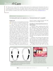
1. No Treatment (Shortened Dental Arch)<br />
- Most patients can function with a shortened dental arch (SDA)<br />
- Requires anterior teeth + 4 occlusal units (symmetric loss) or 6 occlusal units<br />
(asymmetric loss) for acceptable function (opposing PM =1 unit, opposing molars<br />
= 2 units)<br />
- <strong>RPD</strong> doesn’t usually improve function if minimal occlusal units present<br />
2. Fixed partial denture – requires abutments at opposite ends of edentulous space, more<br />
expensive than <strong>RPD</strong>, must grind down abutments, flexes and can fail if too long.<br />
3. Implant supported prosthesis – most costly, closest replacement to natural dentition,<br />
less costly over long term<br />
4. Complete denture (if few teeth left, with poor prognosis); if replacement of missing<br />
teeth is very complex or costly<br />
D. Indications for <strong>RPD</strong>'s<br />
1. lengthy edentulous span (too long for a fixed prosthesis)<br />
2. no posterior abutment for a fixed prosthesis<br />
3. excessive alveolar bone loss (esthetic problem)
Table of Contents - 2<br />
4. poor prognosis for complete dentures due to residual ridge morphology<br />
5. reduced periodontal support of remaining teeth (won't support a fixed prosthesis)<br />
6. cross-arch stabilization of teeth<br />
7. need for immediate replacement of extracted teeth<br />
8. cost/patient desire considerations<br />
Treatment Sequence for Partial Dentures<br />
If an <strong>RPD</strong> is part of planned Treatment:<br />
PLAN THE <strong>RPD</strong> BEFORE BEGINNING ANY OTHER TREATMENT<br />
CLINICAL STEPS<br />
• Survey, tripod, heights of contour<br />
• Draw design on surveyed cast<br />
• Design approved before any treatment started:<br />
o Affects direct restorations<br />
o Can influence need for/preparations for crowns<br />
o Insures <strong>RPD</strong> can be completed successfully<br />
o NO EXCEPTIONS<br />
1. Diagnosis, Treatment Plan, Hygiene<br />
2. Diagnostic Casts<br />
3. Draw design & list abutment modifications on Prosthesis Design page<br />
4. Instructor Approval<br />
5. Complete Phase 1 treatment<br />
6. Abutment modifications<br />
7. Preliminary impression to check abutment modifications<br />
8. Crown or Fixed partial denture’s for removable partial denture abutments (if necessary)<br />
9. Final Framework Impression (must include hamular notches/retromolar pads for distal<br />
extension removable partial dentures<br />
10. Make two casts<br />
<strong>11</strong>. Draw design on 2nd cast<br />
12. Instructor approval/corrections<br />
13. Complete <strong>RPD</strong> Framework Prescription (instructor signature required)<br />
a. Second poured cast with design sent to Lab with 1st pour<br />
14. Inspect wax-up<br />
15. Framework Adjustment<br />
16. Altered Cast impression, if needed<br />
17. Try-in with teeth in wax<br />
18. Process, deliver to patient
E. Components of a Partial Denture<br />
Introduction to <strong>Removable</strong> Partial Dentures - 3<br />
a. Major Connector: The unit of a removable partial denture that connects the parts of one<br />
side of the dental arch to those of the other side. It's principal functions are to provide<br />
unification and rigidity to the denture.<br />
b. Minor Connector: A unit of a partial denture that connects other components (i.e. direct<br />
retainer, indirect retainer, denture base, etc.) to the major connector. The principle<br />
functions of minor connectors are to provide unification and rigidity to the denture.<br />
c. Direct Retainer: A unit of a partial denture that provides retention against dislodging<br />
forces. A direct retainer is commonly called a 'clasp' or 'clasp unit' and is composed of<br />
four elements, a rest, a retentive arm, a reciprocal arm and a minor connector.<br />
d. Indirect Retainer: A unit of a Class I or II partial denture that prevents or resists<br />
movement or rotation of the base(s) away from the residual ridge. The indirect retainer<br />
is usually composed of one component, a rest.<br />
e. Denture Base: The unit of a partial denture that covers the residual ridges and supports<br />
the denture teeth.
Table of Contents - 4<br />
F. Classification<br />
The Need for Classification<br />
There may be over 65,000 possible combinations of teeth and edentulous spaces. A<br />
classification system facilitates communication between dentists. Since there are several<br />
methods of classifying partial dentures, the use of non-standard classifications could lead to<br />
confusion. Therefore, the Kennedy system has been adopted by most dentists.<br />
Kennedy Classification<br />
In 1923, Kennedy devised a system that became popular due to its simplicity and ease of<br />
application. A tremendous number of possible combinations can be reduced to four simple<br />
groups.<br />
Class I - bilateral edentulous areas Class II - unilateral edentulous area<br />
located posterior to all remaining teeth. located posterior to all remaining teeth.<br />
Class III - unilateral edentulous area Class IV - a single, but bilateral<br />
bounded by anterior and (crossing the midline) edentulous<br />
posterior natural teeth. area located anterior to remaining teeth.
Applegate's Rules for Applying the Kennedy Classification<br />
Rule 1: Classification should follow rather than precede extraction.<br />
Introduction to <strong>Removable</strong> Partial Dentures - 5<br />
Rule 2: If the 3rd molar is missing and not to be replaced, it is not considered in the<br />
classification.<br />
Rule 3: If the 3rd molar is present and to be used as an abutment, it is considered in the<br />
classification.<br />
Rule 4: If the second molar is missing and not be replaced, it is not considered in the<br />
classification.<br />
Rule 5: The most posterior edentulous area determines the classification.<br />
Rule 6: Edentulous areas other than those determining classification are called modification<br />
spaces.<br />
Rule 7: The extent of the modification is not considered, only the number.<br />
Rule 8: There is no modification space in Class IV.
Anatomy Tour - 6<br />
Anatomy Tour for Complete and Partial Dentures<br />
Identify the following structures, and answer the corresponding questions regarding anatomy that<br />
is important in the fabrication of complete and partial dentures. The tour does not provide a<br />
comprehensive overview of all critical anatomy, but a sample of structures that are easily visible<br />
in the dentate mouth and on casts. Use your instructor as a resource.<br />
LIPS:<br />
! Vermilion Border<br />
- When a denture provides insufficient lip support (teeth set too far palatally), the<br />
vermilion border becomes narrow, or disappears, adversely affecting appearance.<br />
- Note the width and fullness of the vermilion border of your partner(s), so you have<br />
some idea of the normal shape and contour of these tissues.<br />
! Height, maxillary__________mm, mandibular ___________mm<br />
! Philtrum<br />
- If denture teeth are set too far facially, the maxillary lip is stretched so that the<br />
depression of the philtrum is lost. This looks unnatural. Note the normal appearance of<br />
the philtrum on several of your colleagues. The appearance varies.<br />
! Nasolabial Angle<br />
- The angle measured between the columella of the nose and the philtrum of the lip.<br />
- Normally, approximately 90° as viewed in profile.<br />
! Estimate your partner’s nasolabial angle ________°<br />
! Tissue of the Upper Lip<br />
- Gather the loose tissue of the upper lip between your thumb and index finger, so you<br />
have some idea of the tension of the tissue or support of the lip on a dentate individual.<br />
- If a denture is too “full”, no tissue can be gathered without struggling.<br />
- If there is insufficient denture support, a large portion of the lip can be gathered<br />
CHEEKS:<br />
! Masseter Muscle<br />
- Have a partner clench while you palpate this muscle externally and internally<br />
! What happens internally, when the muscles are active? _______________________<br />
! What aspect of a denture base will be affected by this structure?__________________<br />
! Will this muscle be active when you make an open mouth impression? ____________<br />
! How will you record its contours for your denture base? _______________________<br />
! Who has the most pronounced masseter in your group? ________________________
Anatomy Tour - 7<br />
RESIDUAL RIDGES (Identify on casts, and corresponding portions of dentures)<br />
If ridges are severely resorbed, inform the patient, so they know denture fabrication and retention<br />
will be difficult.<br />
! Maxillary<br />
! Mandibular<br />
VESTIBULES (Identify on casts and corresponding portions of dentures)<br />
If vestibules are short, inform the patient, so they know denture fabrication and retention will be<br />
difficult.<br />
! Maxillary Buccal<br />
! Mandibular Buccal<br />
! Mandibular Lingual<br />
MAXILLA:<br />
! Maxillary Tuberosities<br />
These will be more easily observed in edentulous patients (identify, then see casts)<br />
What influence will these structures have on dentures:<br />
a) if they are oversized?<br />
b) if they are severely resorbed?<br />
c) if they are severely undercut? i.<br />
ii.<br />
! Incisive Papilla<br />
Important landmark for setting of teeth (midline of papilla to labial of incisor !10mm)<br />
On a partner, note the position and size of the papilla in relation to the teeth:<br />
a. How far anterior to the incisive papilla are the central incisors? ____________mm<br />
b. What is the mediolateral relation of the incisive papilla to the midline of the maxillary<br />
teeth ___________________________________<br />
! “Hamular” Notch<br />
The posterior border of a complete denture and some partial dentures must pass through<br />
this notch, between the bony tuberosity and hamulus. Denture border must terminate<br />
on “soft displaceable tissue”, to provide comfort and retention. In some patients the<br />
notch is posterior to where the depression in the soft tissue appears.<br />
! Use the head of your mirror to palpate the notch & mark with an indelible marker.<br />
! Posterior Border of the Hard Palate<br />
- What significance is this border for maxillary complete and partial dentures?<br />
_____________________________________________________________
Anatomy Tour - 8<br />
! Soft Palate<br />
! Vibrating Line<br />
Critical posterior border of complete dentures and some partial dentures. The junction<br />
of movable and immovable portions of the soft palate. If the denture terminates<br />
posterior to this, movements of the soft palate cause it to dislodge and drop. If the<br />
denture terminates anterior to this, on the hard palate, no seal is created, the denture is<br />
unretentive and often uncomfortable.<br />
! Within a group of six students:<br />
! Have an instructor demonstrate how to find and mark the vibrating<br />
line on one student, using an indelible stick<br />
! Have an instructor draw an indelible line at an incorrect position on<br />
one of the two students and a correct position on the other, and guess<br />
which one is correct.<br />
! Locate and draw the vibrating line on the remaining students, check<br />
with instructor.<br />
! Fovea Palatini<br />
Bilateral indentations near the midline of the soft palate. Close to the vibrating line in<br />
many individuals, but not accurate enough for using as a landmark for the posterior<br />
border of the denture<br />
! Median Palatine Raphe (midline palatine suture)<br />
a. A bony midline structure, that can be raised and may require relief when covered<br />
by a denture. Covered with thin mucosa and can ulcerate easily if impinged upon.<br />
b. Occasionally a torus palatinus may be present, creating similar, often more<br />
pronounced problems.<br />
! Identify who has the most prominent raphe/torus ________________________<br />
MANDIBLE:<br />
! Pear Shaped Pad<br />
A soft pad containing glandular tissue, with an inverted pear shape, which is the<br />
posterior terminus of the mandibular complete dentures and Class I & II partial<br />
dentures. The pear shaped pad is usually created from scarring after extractions, and is<br />
therefore more easily seen in edentulous casts.<br />
! Identify the retromolar area or pad on a partner, and have an instructor check.<br />
! Identify the pear shaped pad on the distributed cast<br />
! Buccal Shelf<br />
The primary denture bearing area of a mandibular denture.<br />
Between extraction sites of molars and the external oblique ridge. Does not tend to<br />
resorb much.<br />
! Identify on a partner.
! Anterior Border of the Ramus<br />
- Do not extend dentures posterior to the pear shaped pad onto this structure, or<br />
discomfort will result<br />
Anatomy Tour - 9<br />
! External Oblique Ridge<br />
- Do not extend dentures laterally from the buccal shelf onto this structure or discomfort<br />
will result<br />
! Mylohyoid Ridge (Internal Oblique Ridge)<br />
- Origin of the mylohyoid muscle, largest muscle in the floor of the mouth, which<br />
influences the length of the flange of the lingual flange of a denture.<br />
- Can be quite prominent, and/or sharp, requiring relief in the final denture, particularly<br />
toward the posterior.<br />
! Identify, palpate and indicate the colleague with the most prominent mylohyoid ridge<br />
________________________<br />
! Lingual Tori<br />
Raised bony structures that may require relief when covered by a denture. Covered with<br />
thin mucosa and can ulcerate easily if impinged upon<br />
! Genial Tubercles (no demo)<br />
- Attachment for the genioglossus muscle in the midline of the lingual vestibule.<br />
- When the residual ridge is highly resorbed the tubercles may be higher than the ridge<br />
and present problems for comfort.<br />
FRENA (singular = frenum):<br />
- Frena must be relieved in a denture to allow for movement, without impingement.<br />
- If frena are very prominent, adequate relief can weaken a denture.<br />
- If too much relief is provided, retention is lost.<br />
- Frena can be displaced easily with viscous impression materials such as alginate, so it<br />
is important to check their prominence intraorally.<br />
! Pull the cheeks and lips of a colleague to see how frena change shape.<br />
! Note the shape, size and direction of the following and look on the distributed denture<br />
for corresponding areas to these frena:<br />
! maxillary labial ! maxillary buccal<br />
! mandibular labial ! mandibular buccal<br />
! lingual - these are broader in shape<br />
- these are narrow in shape<br />
! Who has the most prominent frena in your group? _____________________________
Anatomy Tour - 10<br />
OTHER STRUCTURES:<br />
! Pterygo-Mandibular Raphe<br />
- Connects from the hamulus to the mylohyoid ridge.<br />
- Rarely significant, but when prominent, it can cause pain, or loosening of the denture,<br />
requiring a relief “groove ” by the hamular notch<br />
! Have partner open wide as possible -identify raphe.<br />
! Is it prominent? _______________________<br />
! Retrozygomal Fossae (Space)<br />
- Palpate the zygomatic process in the buccal vestibule just buccal to the first maxillary<br />
molar.<br />
- The vestibular space posteriorly is the retrozygomal fossae.<br />
- It is commonly incompletely captured in preliminary impressions without a syringe<br />
technique - this leads to a short flange and non-retentive denture.<br />
! Coronoid Process<br />
- Place mirror head lateral to tuberosity, have partner move mandible to opposite side.<br />
- Note binding or pain during this excursion.<br />
- This gives some indication of the width of the space available for a denture flange.<br />
- If the flange is made too thick, it will cause pain and sometimes dislodgment.
Irreversible Hydrocolloid Preliminary Impressions<br />
Preliminary Impressions - <strong>11</strong><br />
Selection of a stock tray:<br />
1. A space of 5 -7 mm should exist between the tray and the tissues to provide bulk for strength<br />
and accuracy of the material.<br />
2. The tray should be just short of the labial vestibule and slightly beyond the vibrating line<br />
3. Compound may be placed on peripheries of stock tray to extend borders if needed.<br />
Extension should be made only to provide coverage of critical anatomy, not for the purpose<br />
of displacing or distorting the vestibular tissues, which should be registered accurately to<br />
obtain a peripheral seal on a denture.<br />
Handling the Material:<br />
1. Pre-measure material – do not take containers to your operatory. Do not handle containers<br />
with contaminated gloves/hands. This makes infection control easier.<br />
2. Do not leave containers open in a humid environment - humidity and high temperatures can<br />
cause deterioration of the powder.<br />
3. Do not mix in a bowl contaminated with dental stone - gypsum can cause acceleration of the<br />
alginate. Conversely alginate contamination of a bowl used to mix stone can diminish the<br />
strength of the cast or model produced. Keep separate bowls and spatulas for alginate and<br />
stone.<br />
Measuring and Mixing alginate<br />
1. Fluff the powder before measuring, making sure there are no large voids in the scoop. Do<br />
not tap the scoop more than once or twice, since this will compact the powder, and result in a<br />
thicker mix.<br />
2. Measuring by weight is more accurate than by volume.<br />
3. Ratio of 1 scoop powder : l measure water.<br />
4. 3 scoops of powder is sufficient for most arches.<br />
5. For adjusting the setting time, regulate water temperature rather than the water/powder ratio,<br />
which can affect strength of the impression.<br />
6. Mix for up to 45 seconds, until a smooth creamy consistency is reached. No lumps or<br />
powder should remain visible in the mix.<br />
Making the impression<br />
1. Lightly dry the teeth and mucosa. Don’t desiccate the teeth or the alginate may stick to<br />
them.<br />
2. Wipe alginate onto the occlusal surfaces of any teeth.<br />
3. When seating the tray, don't bottom out on the teeth or the residual ridge, as this will result in<br />
distortions of the tissue or movement of the teeth.<br />
4. Wait to remove the impression until the material is firm (approximately one minute after<br />
initial set).<br />
5. Pull the lip up to allow air to break the seal with the tissues. This will make the impression<br />
easier to remove. Several drops of water placed in the vestibule can also aid in breaking the<br />
seal. Remove rapidly, to prevent significant permanent deformation.
Preliminary Impressions - 12<br />
6. Wrap the impression in a damp towel (completely wet, then wring out to eliminate dripping<br />
water), then pour within 12 minutes to avoid significant distortion.<br />
7. If the impression is placed on a firm surface, the alginate may distort if it is unsupported by<br />
the tray and in contact with the supporting surface. Support the impression by the handle or<br />
the tray, rather than unsupported portions of the impression, until the preliminary cast has<br />
been poured and the stone has set.<br />
Evaluating Irreversible Hydrocolloid Impressions<br />
1. The alginate should be properly mixed, smooth and creamy.<br />
2. The tray should be centered over ridge.<br />
3. No significant contact should occur between the tray with soft tissues or teeth.<br />
4. No-large voids in the impression.<br />
5. All critical anatomy should be recorded (hamular notches, retromolar pads, etc.).<br />
Pouring a Model<br />
1. Weigh the powder for the stone, measure water for the corresponding amount of powder<br />
2. Vacuum mix the stone (this takes less time to spatulate than hand mixing and it results in a<br />
stronger cast)<br />
3. Use a two-pour technique - pour stone into the impression first, then wait for the cast to set<br />
before inverting the model to add a base to the cast. This produces casts with superior<br />
surface strength.<br />
Two-Pour Technique<br />
1. Rinse the alginate impression. Spray all surfaces with disinfectant solution and seal for 10<br />
minutes.<br />
2. Use the vibrator and flow the stone into the impression slowly, watching the stone fill all the<br />
indentations of the impression. Modulate speed of pouring the impression by tilting the tray<br />
back and forth. If the stone mixture fills the impression too quickly, air will get trapped in<br />
undercuts and voids will be incorporated into the cast. To delay the filling of the impression,<br />
tilt the impression in the opposite direction of the flow of the stone, reduce the speed of the<br />
vibrator, or press the impression less firmly against the vibrator.<br />
3. Leave some rough areas or projections above on the exposed surface of the stone to help<br />
attach the base that will be attached after this first pour has set.<br />
4. Let the stone set to a firm consistency (approximately 30 minutes). This will ensure that the<br />
surface of the cast has superior strength due to the heavier and denser stone particles settling<br />
toward the incisal and occlusal surfaces.<br />
5. Make a patty of stone and invert the alginate impression with the set first pour onto the base.<br />
Adapt the new stone to the existing stone, but be careful not to cover any areas of the tray.<br />
Otherwise it may be difficult to remove the tray without damaging the cast.<br />
6. Trim excess stone from the base with the spatula while the stone is still soft.<br />
7. Separate the alginate impression from the stone cast after 30 minutes.
Preliminary Impressions - 13<br />
Trimming<br />
1. Make sure the model is moist during trimming, so that debris from the trimmer does not<br />
attach to the cast. Soak the model by immersing it in slurry water, or by allowing just the<br />
base of cast to contact clear tap water. Prolonged immersion in tap water can lead to erosion<br />
of the cast.<br />
2. Cast should be minimum of 10-12mm (.5 inch) in thinnest part<br />
3. Trim the base on the model trimmer parallel to ridges.<br />
4. Leave the mucous membrane reflection intact for making a custom tray<br />
5. The casts should have the following contours and dimensions:<br />
Cross Section through Casts<br />
Master Cast Diagnostic Cast<br />
For Master casts, impressions are boxed and trimmed with a 3mm wide by 3mm deep<br />
land area to aid in processing of acrylic. For diagnostic casts used for making custom<br />
trays, the land area should be omitted so that the tray material is easier to trim and<br />
remove from the cast<br />
Outline of Bases for Trimmed Casts<br />
Follow the contour of the ridges, with rounded angles
Surveying, Path of Insertion, Guiding Planes - 14<br />
Surveying, Path of Insertion, Guiding Planes<br />
A path of insertion (or removal) is the path along which a prosthesis is placed (or removed)<br />
intraorally. A removable partial denture is usually fabricated to have a single path of insertion or<br />
removal from the mouth. A single path of insertion is advantageous because it:<br />
1. equalizes retention on all abutments<br />
2. provides bracing and cross-arch stabilization of teeth<br />
3. minimizes torquing forces of the partial denture<br />
4. allows the partial denture to be removed without encountering interferences<br />
5. directs forces along the long axes of the teeth<br />
6. provides frictional retention from contact of parallel surfaces on the teeth<br />
In order to provide a single path of insertion for a partial denture, some axial surfaces of<br />
abutments must be prepared so that they parallel the path of insertion. These parallel surfaces<br />
are called guiding planes.<br />
Guiding planes are prepared wherever rigid components of a partial denture contact abutment<br />
teeth. Specifically, guiding planes should usually be prepared for:<br />
1. Proximal plates<br />
2. Bracing arms<br />
3. Rigid portions of retentive clasps<br />
The dental surveyor is a diagnostic instrument used to select the most favorable path of<br />
insertion and aid in the preparation of guiding planes. It is an essential instrument in designing<br />
removable partial dentures. The act of using a surveyor is referred to as surveying.<br />
Other Uses of a Surveyor:<br />
1. Locating soft tissue undercuts, which can influence the extent of the denture base, the<br />
type of direct retainers and the path of insertion selected.<br />
2. Contouring wax patterns for fixed restorations that will be partial denture abutments.<br />
3. Machining parallel surfaces on cast restorations.<br />
4. Blocking out undesirable undercuts on master casts.<br />
5. Placing intracoronal retainers (precision attachments).<br />
6. Recording the cast position in relation to the selected path of insertion (tripoding).
Parts of a Surveyor:<br />
Surveying, Path of Insertion, Guiding Planes - 15<br />
1. Surveying Table (Cast Holder): The part of the surveyor to which a cast can be attached.<br />
Through the use of a ball and socket joint it allows the cast to be oriented at various tilts and<br />
to be fixed along one of these planes.<br />
2. Surveying Arm: A vertical arm used to analyze the parallelism of various axial cast<br />
surfaces. It contains a holder so that several surveying tools may be attached and used.<br />
3. Surveying Tools:<br />
a. Analyzing Rod - A thin straight metal rod<br />
used to analyze contours and undercuts.<br />
This is the principal tool used in surveying.<br />
The side of analyzing rod is brought into<br />
contact with surfaces of the proposed<br />
abutment teeth to analyze their axial<br />
inclinations. This rod is easily bent and once<br />
bent is difficult to straighten. Use it carefully.<br />
b. Carbon Marker - Rods similar to pencil leads which can be used to mark the<br />
location of the height of contour on a dental cast. Some surveyors use a protective<br />
sheath to prevent or reduce breakage of the carbon markers.<br />
c. Metal Gauges - Metal rods with terminal ledges or lips of various widths (the most<br />
commonly used are 0.01" and 0.02"). Undercut dimensions can be measured on teeth<br />
by bringing the vertical shaft of the gauge in contact with a tooth and then moving the<br />
surveying arm up or down until there is also contact with the terminal lip.<br />
d. Wax Trimmer - A tool with a straight sharp edge, which parallels the surveying arm.<br />
It is used to contour waxed crowns for partial denture abutments, or to place blockout<br />
for a partial denture framework. It is used with a dragging or shaving motion to<br />
remove thin layers.
Surveying, Path of Insertion, Guiding Planes - 16<br />
Selecting the Path of Insertion of a <strong>Removable</strong> Partial Denture<br />
A path of insertion is selected to provide the best combination of retentive undercuts and<br />
parallel surfaces for ALL ABUTMENTS. Use the following steps to do so:<br />
STEP 1 Place the cast on the surveyor table and orient the plane of occlusion relatively<br />
horizontal. The final tilt of the cast for the ideal path of insertion is seldom more<br />
than 10° from this position.<br />
STEP 2 Place the analyzing rod against the axial surface of a proposed abutment teeth (any<br />
tooth adjacent an edentulous space). The tip of the rod should be at the level of the<br />
free gingival margin. The point where the tooth touches the analyzing rod is greatest<br />
convexity (bulge) of a tooth and is called the height of contour.<br />
The position of the height of contour can be changed by tilting the cast. The area on a<br />
tooth occlusal to the height of contour is called the suprabulge area. All portions of<br />
a direct retainer that are rigid or semi-rigid must be located in this area. The area<br />
gingival to the height of contour is an undercut and is called the infrabulge area.<br />
The retentive portions of direct retainers are located in this area, since they can flex to<br />
pass over the height of contour.<br />
Note that when cast is tilted and the surveying arm remains vertical, the height of contour (large<br />
arrows) changes, as does the distance of the analyzing rod to the tooth (small arrows)<br />
STEP 3 Tilt the cast to gain maximum parallelism of axial surfaces of all of the proposed<br />
abutments. Maximum parallelism is present when the heights of contour of all teeth<br />
and all surfaces are as close as possible to the same position occluso-gingival. An<br />
additional check for maximum parallelism is that equal amounts of undercut are<br />
present on all abutments and all abutment surfaces. Check the mesial and distal tooth<br />
surfaces while tilting the cast anterior-posteriorly (A-P). While maintaining the same<br />
A-P tilt check facial and lingual parallelism. Lock the tilt of the cast when maximum<br />
parallelism is achieved.<br />
STEP 4 Use an undercut gauge to check for adequate and relatively equal retentive,<br />
undercuts for retentive arms on all abutments. Alter the tilt of cast if required.
Surveying, Path of Insertion, Guiding Planes - 17<br />
STEP 5 Change the tilt of the cast if there are any major soft tissue interferences (i.e.<br />
mandibular tori, residual ridge undercuts), or if the selected path of insertion will<br />
cause an esthetic problem (i.e. clasp would have to be placed to far incisally on the<br />
facial surface of an anterior tooth, as when the height of contour or required depth of<br />
undercut is too close to the incisal or occlusal surface).<br />
STEP 6 Lock the diagnostic cast in position on the surveying table and mark the heights of<br />
contour on the denture abutments and soft tissues with the carbon marker. When<br />
marking the heights of contour, ensure that the carbon tip follows close to the free<br />
gingival margin so that you do not register a false height of contour.<br />
The heights should be relatively equal occluso-gingivally.<br />
STEP 7 Tripod the diagnostic cast so that the selected path of insertion may be easily found<br />
for future reference.<br />
The Optimal Path of Insertion<br />
The optimal path of insertion of a partial denture is determined by:<br />
A. Retentive undercuts - equalized on all abutments.<br />
Clasp has different path of escapement (dashed arrow) than<br />
guiding plane (solid arrows) and therefore must flex when the<br />
denture is removed. This provides retention for the denture.<br />
Retentive clasps(•) oppose each other when correctly designed (left). Retention at each principle<br />
abutment should balance that of the tooth on the opposite side of the arch (i.e. equal in<br />
magnitude and opposite in relative location).
Surveying, Path of Insertion, Guiding Planes - 18<br />
B. Interferences - A path of insertion must be selected so that the prosthesis may be inserted<br />
and removed without encountering tooth or soft tissue interferences. Tooth interferences are<br />
usually encountered where rigid elements of the partial denture would require placement in<br />
areas of undercut. Since rigid elements do not flex, such a partial denture will not seat.<br />
Tooth interferences are often encountered in the bucco- or linguo-occluso-proximal point<br />
angles, where the height of contour is high and where rigid portions of the clasp assemblies<br />
must be placed.<br />
Since only the terminal end of the retentive arm<br />
flexes (circled area), the clasp on the left will<br />
lock on the cast. The rigid portion of the clasp<br />
will not release from the undercut. The clasp on<br />
the right will release since only the flexible tip is<br />
in the undercut.<br />
When soft tissue undercuts exist (i.e. mandibular tori, residual ridge undercuts), the rigid<br />
denture base can cause abrasion, irritation and /or ulceration as it is forced over the tissue.<br />
As such, a path of insertion that involves interferences should only be selected if the<br />
interferences can be eliminated by tooth preparation or reasonable blockout of the master<br />
cast. If the interferences cannot be eliminated or minimized, then a different path of<br />
insertion must be considered, even if less desirable guiding plane and retentive areas must<br />
be selected.<br />
Soft tissue undercuts require that the tissue be impinged<br />
upon as the major connector or denture base passes over it.<br />
If a large undercut is blocked out, the connector or base will<br />
be remote from the tissue and collect food and debris.<br />
C. Esthetics. A path of insertion should be selected to provide the most esthetic placement of<br />
artificial teeth and the least amount of visible metal on the abutment teeth. Ensure that the<br />
retentive undercut and the height of contour are not placed too far occlusally, so that the<br />
retentive clasp and that anterior proximal plates are close to the gingival contours making<br />
these components as inconspicuous as possible.<br />
D. Guiding planes. Guiding planes are flat surfaces prepared on abutment teeth. Flat, rigid<br />
elements of the partial denture (bracing elements and proximal plate minor connectors) fit<br />
against these surfaces to ensure that a partial denture seats along one path of insertion.<br />
Guiding planes are used to control and limit the directions of movement of a removable<br />
partial denture as it is being inserted, removed or while it is in function. To do this, bracing<br />
elements or proximal plates should, whenever possible, be the initial portions of the<br />
partial denture to contact the abutments. In this way, the teeth are stabilized from the<br />
potential moving forces as retentive elements of direct retainers flex over the heights of<br />
contour into the retentive undercuts.
Guiding planes are most effective when they:<br />
Surveying, Path of Insertion, Guiding Planes - 19<br />
When the retentive arm (•) contacts the tooth first, it can<br />
cause movement of the tooth since the tooth is not<br />
stabilized to resist displacement. When the rigid bracing<br />
or reciprocal arm contacts first, it braces the tooth so the<br />
retentive arm cannot displace it.<br />
a. are parallel<br />
b. include more than one common axial surface (e.g. proximal and lingual surfaces)<br />
c. are directly opposed by another guiding plane (e.g. facing guiding planes in a<br />
modification space)<br />
d. are placed on several teeth<br />
e. cover a large surface area (long and/or broad)<br />
These guiding planes are parallel, include<br />
more than one common axial surface (i.e.<br />
distal of premolar, mesial of molar), directly<br />
oppose one another and are fairly long. They<br />
will be very effective.<br />
When marked with a carbon marker, well-prepared guiding planes appear as wide survey lines:
Surveying, Path of Insertion, Guiding Planes - 20<br />
Selection and Preparation of Guiding Planes:<br />
a. A path of insertion is selected.<br />
b. The number and position of guiding planes is selected.<br />
c. With the diagnostic cast as a guide, parallel surfaces are prepared intraorally with straight<br />
cylindrical burs (#<strong>11</strong>56 or #557L or equivalent cylindrical bur). The surveyed cast should<br />
be nearby for comparison, so that the bur can be placed in the same relationship to the<br />
tooth as the analyzing rod makes with the diagnostic cast.<br />
The bur should be placed at the same<br />
angulation as the surveying rod. The<br />
triangular space below the height of<br />
contour should appear to be the same.<br />
d. Guiding planes should be at least 1/2 to 1/3 of the axial height of the tooth (generally a<br />
minimum of 2 mm in height). Use a light sweeping stroke continuing past the bucco- and<br />
the linguo proximal line angles. Reduction should follow the bucco-lingual curvature of<br />
the tooth, rather than slicing straight across the tooth. Guide planes for distal-extension<br />
cases should be slightly shorter to avoid torquing of the abutment teeth. Lingual guiding<br />
planes for bracing or reciprocal arms should be 2-4 mm and ideally be located in the<br />
middle third of the crown, occluso-gingivally. Use a good finger rest to establish parallel<br />
planes.<br />
e. If tooth surfaces selected for guiding planes are already parallel to the path of insertion,<br />
little if any tooth modification may be necessary.<br />
f. The prepared surfaces are polished rubber wheels or points.<br />
g. Guiding planes are the first features prepared intraorally. If occlusal rest seats are prepared<br />
initially, placement of a proximal guiding plane will remove some of the rest seat<br />
preparation, and result in a narrowed rest with a sharp occluso-proximal angle.
Surveying, Path of Insertion, Guiding Planes - 21<br />
The Effects of Guiding Planes on Retention and Stability<br />
1. Guiding Planes Maintain Retention<br />
Retention is gained by the flexible retentive tip of the clasp engaging an undercut of an<br />
abutment. Retentive undercuts exist only in relation to a fixed plane. If an undercut is<br />
found on a diagnostic cast, and the cast is tilted in another direction, the undercut can be<br />
eliminated. Likewise, in the mouth, if the partial denture does not have a single path of<br />
insertion (as dictated by guiding planes) the prosthesis could be rotated so that the retentive<br />
undercuts would be eliminated. The denture could then be easily displaced.<br />
Point contact of the reciprocal arm allows rotation of the partial denture and release of the<br />
retentive arm (left and middle). A broad flat plane does not (right).<br />
2. Guiding Planes Minimize the Need for Retention<br />
The use of too many clasps or the use of clasps with large undercuts can impair the health<br />
of the periodontium. Frictional retention from parallel guide planes minimizes the retention<br />
required from direct retainers.<br />
3. Guiding Planes Stabilize Teeth<br />
Guiding planes with intimate, firm and continual contact with the prosthesis are effective in<br />
stabilizing teeth. Stability can be important if there is mobility due to periodontal bone loss.<br />
This effect is most pronounced in Class III partial dentures. In Class I and II partial<br />
dentures, stability is compromised by the lack of posterior abutments. These dentures tend<br />
to rotate more and produce a torquing force, if the principal abutments are locked into the<br />
denture. Slightly shorter guiding planes are used in distal extension cases to minimize this<br />
torquing action.<br />
Loading of a Class I denture base causes rotation around the rest seat. A short guiding<br />
plane allows rotation into the gingival relief area. A long guiding plane has no area to<br />
move and thus immediately torques the tooth.
Surveying, Path of Insertion, Guiding Planes - 22<br />
Alteration of Other Axial Contours<br />
While guiding plane surfaces are the most common axial tooth preparations made for removable<br />
partial dentures, other axial preparations may also be required. These include:<br />
A. Lowering Height of Contours<br />
1. Lowering height of contours to eliminate tooth interferences in areas where rigid<br />
frameworks elements will be placed (such as rigid portions of retentive arms).<br />
2. Lowering height of contours to improve esthetics (e.g. to allow retentive arms to be<br />
placed more gingivally to reduce clasp display).<br />
When preparing axial contours for these situations, the heights of contour are most<br />
quickly lowered by placing the bur parallel to the path of insertion.<br />
B. Raising Height of Contours<br />
The only time that a height of contour would be raised would be when there is no retentive<br />
undercut present or when the undercut is so far gingival that the retentive tip would either<br />
impinge on the free gingival margin or cause a hygiene problem due to its proximity to the<br />
free gingival margin. In general, the inferior portion of the retentive undercut should be at<br />
least 1mm above the free gingival margin. Raising the height of contour is only feasible<br />
when the axial surface is parallel or slightly divergent to the path of insertion. If the<br />
surface is grossly divergent from the path of insertion, then raising the height of contour<br />
may be impossible.<br />
The tooth on the right is grossly<br />
divergent from the path of insertion,<br />
so that excessive preparation is<br />
required just to gain the appropriate<br />
undercut. Dentin, or in extreme<br />
cases, the pulp could be exposed.<br />
Minimal preparation will be required<br />
on the tooth on the left since its long<br />
axis is close to the path of insertion.<br />
Raising the height of contour for retentive undercuts can be accomplished by:<br />
1. Preparing a retentive undercut. Prepare an ovoid undercut with the inferior border at<br />
least 1 mm from the free gingival margin, using a round or chamfer diamond bur.<br />
Correct Should be more Too close to<br />
ovoid, like clasp free gingival<br />
tip margin
Surveying, Path of Insertion, Guiding Planes - 23<br />
2. Place composite resin above the position of the retentive tip, using rubber dam isolation.<br />
Place a Mylar matrix to separate the tooth from adjacent teeth. Clean the tooth with flour<br />
of pumice, etch, apply bonding agent and place the composite with plastic instrument.<br />
Place and contour the material as indicated below. Ensure there is adequate undercut<br />
only in the area needed, even after polishing.<br />
If the tooth is very<br />
divergent from the path<br />
of insertion, the<br />
composite will have to be<br />
grossly over contoured<br />
(right), which is not<br />
advisable for hygienic<br />
reasons. Changing the<br />
path of insertion or<br />
uprighting the tooth<br />
orthodontically may be<br />
preferable alternatives.<br />
3. Combination of Preparing an Undercut and Placing Composite Resin<br />
This is most commonly done when the tooth is more divergent from the path of insertion<br />
than usual. When possible, it is preferable to prepare retention in enamel rather than<br />
place a resin bonded undercut. Preparation in enamel, when feasible, is less time<br />
consuming, less expensive and probably more hygienic over an extended period of time.<br />
Summary of <strong>Removable</strong> Partial Denture Abutment Modifications<br />
After a path of insertion is selected and a partial denture design has been formulated, tooth<br />
preparations are made according to the following sequence.<br />
1. Prepare guiding planes along the path of insertion for:<br />
a. Proximal plates<br />
b. Bracing arms<br />
c. Rigid portions of retentive clasps<br />
2. Lower heights of contour to eliminate interferences and improve esthetics.<br />
3. Raise heights of contour for retentive arm tips by preparation and/or placement of composite<br />
resin.<br />
4. Rest seat preparations or placement of bonded composite rest seats.
Rests and Rest Seats - 24<br />
A. Definitions<br />
Rests and Rest Seats<br />
i. Rest: A rigid component of a removable partial denture which rests in a recessed<br />
preparation on the occlusal, lingual or incisal surface of a tooth to provide vertical support<br />
for the denture. Although a rest is a component of a direct retainer (retentive unit, clasp<br />
assembly), the rest itself is classified as a supporting element due to the nature of its<br />
function.<br />
a. Occlusal rest - a rest placed on the occlusal surface of a bicuspid or molar.<br />
b. Lingual (cingulum) rest - A rest placed on the cingulum of an anterior tooth (usually<br />
the canine). Rests may also be placed on the lingual of posterior teeth by creating a<br />
ledge of the tooth surface (prescribed for surveyed crowns).<br />
c. Incisal rest - A rest placed on an anterior tooth at the incisal edge.<br />
d. Intracoronal (precision) rest - A rest consisting of precision manufactured<br />
attachments that are placed within the coronal contours of a crown or retainer.<br />
ii. Rest Seat: A portion of a tooth selected and prepared to receive an occlusal, incisal or<br />
lingual rest.<br />
B. Functions of Rests<br />
1. To direct forces along the long axis of the abutment tooth.<br />
2. To prevent the denture base from moving cervically and impinging gingival tissue.<br />
3. To maintain a planned clasp-tooth relationship.<br />
4. To prevent extrusion of abutment teeth.<br />
5. To provide positive reference seats in rebasing and/or impression procedures.<br />
6. To serve as an indirect retainer by preventing rotation of the partial denture (Class I or II<br />
<strong>RPD</strong>’s only).
C. Preparation of Rest Seats<br />
Rests and Rest Seat - 25<br />
Rests seats should be prepared using light pressure with a high-speed handpiece with or without<br />
water spray. Since minimal preparation is usually performed, minimal heat is generated. Good<br />
visibility is required so that water coolant can be eliminated.<br />
Since preparations are usually entirely in enamel it is best to avoid anesthesia so the patient can<br />
inform the dentist when sensitivity is felt.<br />
Occlusal rest seats can be prepared with medium round burs (#2 and primarily the #4 sizes).or<br />
diamonds (e.g. 801-016, 38006-135)<br />
Guiding planes and cingulum rest seats can be prepared with a long, medium diameter<br />
cylindrical bur or diamond (e.g. #57L; 8837K-014).<br />
D. Rest Seat Form<br />
Rest seats should have a smooth flowing outline form (i.e. no sharp line angles).<br />
1. Occlusal Rest Seats<br />
(a) The outline of an occlusal rest seat is a rounded triangular shape with its apex<br />
nearest to the centre of the tooth.<br />
(b) The base of the triangular shape is at the marginal ridge and should be approximately<br />
one third the bucco-lingual width of the tooth.<br />
(c) The marginal ridge must be lowered and rounded to permit a sufficient bulk of metal<br />
to prevent fracture of the rest from the minor connector (1 to 1.5 mm)
Rests and Rest Seats - 26<br />
(d) The floor of the rest seat should be inclined towards the centre of the tooth, so that the<br />
angle formed by the rest and the minor connector should be less than 90°. This helps to<br />
direct the occlusal forces along the long axis of the tooth.<br />
A clinician can test to see if a rest seat is ‘positive’ (i.e.
Rests and Rest Seat - 27<br />
When occlusal rest seats are prepared next to an edentulous space the morphology follows<br />
conventional form.<br />
When a single occlusal rest seat is prepared next to an adjacent tooth the form is modified. The<br />
rest seat is not flared to the facial line angle. Instead, the lingual line angle is flared more<br />
dramatically to provide additional space for the minor connector.<br />
When embrasure occlusal rest seats are prepared on adjacent teeth, the form is also modified.<br />
Additional tooth structure is removed in the marginal areas to provide at least 1.5 mm of room<br />
for the embrasure clasps. The rest seats are flared more dramatically to the facial and the lingual<br />
line angles to provide additional space for the retentive arms and minor connector. Inadequate<br />
clearance in these areas will result in occlusal interferences with the opposing teeth and/or<br />
inadequate thickness and strength of framework. Care must be taken to ensure all line angles are<br />
smoothed.<br />
2. Lingual Rest Seats<br />
Lingual or cingulum rests on anterior teeth are often utilized when no posterior teeth are<br />
present or when indirect retention is necessary. The anterior tooth most readily adaptable<br />
to a cingulum rest is the canine, due to its well-developed cingulum. When a canine is not<br />
available, the cingulum of an incisor may be used. In some instances, multiple rests spread<br />
over the cingula of several teeth may be required, in order to minimize stress on the teeth.<br />
Root form, root length, inclination of the tooth, and the crown-root ratio must be<br />
considered in the planning for the use of such rests.<br />
Cingulum Rest Seat Form<br />
a. The rest seat, from the lingual aspect assumes the form of a broad inverted "V'<br />
maintaining the natural contour often seen in the canine cingulum. From the incisal<br />
view the rest seat is broadest at the central aspect of the canine (approximately 1<br />
mm). The proximal view demonstrates the correct angulation of the floor of the rest<br />
seat (< 90°). The borders of the rest seat are slightly rounded to avoid sharp line<br />
angles in its preparation. As with occlusal rest seats, a preparation will test as<br />
‘positive’ if an explorer tip does not slip off the rest seat when pulled lingually from<br />
the base of the rest seat.
Rests and Rest Seats - 28<br />
Correct Preparation<br />
The cingulum rest seat should be prepared in the bulk of the cingulum to minimize tooth<br />
reduction. The cavosurface should be less than 90° to prevent orthodontic movements of the<br />
tooth.<br />
Preparation Too High<br />
If the preparation is started too high above the cingulum proper, much of the lingual surface<br />
of the tooth above the cingulum will need to be reduced, in order to obtain sufficient width<br />
for support. On maxillary anteriors, this may also cause the rest to interfere with the<br />
opposing tooth.<br />
Preparation Too Low<br />
If the preparation is started too low, much of the cingulum will need to be reduced, in order<br />
to obtain sufficient width for support. Enamel is thinner in this area, and preparation could<br />
result in dentinal exposure, resulting in sensitivity. If correction of the outline form or depth<br />
is required, there will be little tooth structure remaining to make such changes.
Rests and Rest Seat - 29<br />
b. Care must be taken not to create an enamel undercut that would interfere with the<br />
placement of the denture. A medium or large diameter cylindrical fissure bur should<br />
be utilized approaching along the long axis of the tooth. Approach from a horizontal<br />
direction will often result in creation of an undercut incisal to the rest seat.<br />
Correct Incorrect<br />
A rest placed on an unprepared cingulum results in force being applied in a labial<br />
direction. Orthodontic movement will occur with osteoclastic activity around the<br />
centre of rotation of the root. A rest seat prepared in the cingulum of the tooth results<br />
in the forces being directed along the long axis of the tooth.<br />
The following factors should be considered prior to the preparation of a cingulum rest seat on a<br />
natural tooth:<br />
1. The prominence and shape of the natural cingulum. Cingulum rest seats must be placed in<br />
sound tooth structure or restorations. Where the ideal position of the rest seat would be<br />
upon an amalgam restoration it is advisable to select a different tooth surface or replace the<br />
restoration with an onlay or crown, since the flow characteristics and relatively low yield<br />
strength of the material make the possibility of fracture high. Where the cingulum is not<br />
prominent or when preparation might encroach upon the pulp, other means of securing a<br />
lingual rest seat must be considered (i.e. selection of a different tooth, use of a composite<br />
bonded rest seat, onlay, crown etc.)
Rests and Rest Seats - 30<br />
2. The interocclusal relationship of a maxillary tooth with the incisal edge of the opposing<br />
mandibular tooth when the former will be prepared for a cingulum rest. When a deep<br />
vertical overlap exists, care must be taken to ensure that the mandibular tooth does not<br />
prematurely contact the area of the planned metal framework. Mounted diagnostic casts<br />
should be used to assess this relationship, by drawing a line on the lingual surface of the<br />
maxillary abutment, where the mandibular tooth touches when the models are in contact<br />
with each other. The cingulum rest seat preparation should be 1.5-2.0 mm below this line<br />
to allow for adequate framework strength.<br />
Composite Buildups for Cingulum Rests:<br />
Correct Incorrect<br />
When a cingulum is poorly developed, with insufficient bulk for preparation for a cingulum rest<br />
seat, a rest seat can be made using composite resin. Research has demonstrated that these<br />
"bonded rest seats" can provide acceptable strength and longevity.<br />
The cervical portion of the buildup should have a flat emergence profile (not over contoured)<br />
with bulk increasing toward the incisal. Enamel should be pumiced, rinsed, etched, bonded, in a<br />
relatively dry, isolated environment. Care must be taken to ensure the cervical composite is well<br />
adapted and that most of the form is finalized prior to curing. The bonded rest seat should be<br />
smooth and well polished, with no sharp line angles.<br />
Composite Bonded Rest Seat Form
Rests and Rest Seat - 31<br />
Round Lingual Rest Seat Form<br />
Round rest seats are occasionally prepared on the mesial of the canine teeth when the use of a<br />
typical cingulum rest is contraindicated (i.e. large restoration, lack of clearance with the<br />
opposing teeth, poorly developed cingulum). These rest seats are prepared spoon shaped, similar<br />
to an occlusal rest seat, with reduction of the mesial marginal ridge. However, preparation is<br />
more difficult due to the incline of the lingual surface of the canine and more tooth structure<br />
must often be removed. Round lingual rest seats can be easily incorporated into crowns where<br />
there is usually sufficient linguo-proximal reduction, without the problem regarding exposure of<br />
dentin. Use care to ensure that no undercuts are prepared in relation to the path of insertion<br />
if a round bur is used.<br />
3. Incisal Rests<br />
Incisal rests are inferior to lingual rests both mechanically and esthetically. Normally they<br />
should not be used unless it is impossible to place a lingual rest seat or a composite bonded<br />
rest seat.<br />
a. An incisal rest seat is usually placed on the mesio- or disto-incisal angle of the incisor<br />
teeth with the deepest portion towards the centre of the tooth. It is predominantly<br />
used as an auxiliary rest or an indirect retainer.<br />
b. It is usually used on the mandibular incisor where the lower lip can cover, as much as<br />
possible, the metal of the rest that shows at the incisal edge.<br />
Mechanically, a lingual rest is preferable to an incisal rest, because the lingual rest is<br />
placed nearer to the center of rotation of the tooth and therefore, will have less tendency to<br />
tip the tooth.
Major Connectors - 32<br />
Definition<br />
Major Connectors<br />
The unit of a removable partial denture that connects the various parts of the denture. Its<br />
principal functions are to provide unification and rigidity to the denture.<br />
Functions of a Major Connector<br />
1. Unification<br />
A major connector units all other components of a partial denture so that the partial denture<br />
acts as one unit.<br />
2. Stress Distribution<br />
By unifying all elements of a partial denture the major connector can distribute functional<br />
loads to all abutment teeth, so that no one abutment is subjected to extreme loading.<br />
Unification of the direct retainers with the denture bases aids in distributing forces between<br />
both the teeth and the mucosa. This is particularly important in Class I and II partial<br />
dentures. In some maxillary cases a major connector with broad palatal contact is selected.<br />
In these situations the broad base offers additional support, distributing stress over a larger<br />
area.<br />
3. Cross-Arch Stabilization (Counterleverage)<br />
By uniting one side of the arch to the other bracing elements on one side of the arch can aid<br />
in providing stability to the other. This can aid in dissipating twisting and torquing forces.<br />
Requirements of a Major Connector<br />
1. Rigidity<br />
Rigidity is necessary to ensure that the partial denture functions as one unit. If the denture<br />
flexes, stress distribution and cross arch stabilization can be compromised since different<br />
portions of the denture can move independent of the others. A major connector can be<br />
made more rigid by:<br />
a. using a more rigid alloy (Chrome-cobalt > gold alloys; cast > wrought metal)<br />
b. using a 1/2 round or 1/2 pear shaped bars (more rigid than flat bars)<br />
c. increasing the bulk as the length increases<br />
d. corrugating linguo-plate or rugae areas.<br />
2. Non-Interference with the Soft Tissues<br />
Major connectors should not enter into undercut areas unless tissue impingement can be<br />
avoided by changing the selected path of insertion or by using minor undercut blockout. In<br />
addition, connectors should not end on the crest of rugae or at the free gingival margin. If<br />
terminated in these areas, it is possible that movement of the connector could cause tissue
Major Connectors - 33<br />
impingement that could compromise blood flow. Major connectors should be placed as<br />
far<br />
from the free gingival margin as possible and practical. Where it is necessary to cross<br />
the gingival margin (i.e. with a minor connector), it should be done abruptly and<br />
perpendicular to the margin. In addition, a small amount of relief is used over the area<br />
where crossing occurs, in order to minimize impingement.<br />
Other areas of potential tissue impingement are the various hard structures such as the midpalatal<br />
suture or mandibular tori. Where it is necessary to cross these areas, relief should<br />
be used so that the connector does not fulcrum on them during movement.<br />
Soft tissue movements during function must also be allowed. Of particular importance are<br />
the mandibular lingual frenum and the maxillary movable soft palate. Before a partial<br />
denture design is finalized, the clinician should make a careful examination of the<br />
mouth to ensure the selected major connector will not interfere with any of these<br />
anatomical structures.<br />
3. Food Impaction<br />
This can be minimized by locating the margins of the connectors at the prescribed distance<br />
from the free gingival margin and by taking care that the presence of minor connectors,<br />
clasp arms and major connectors does not create "traps" or large concavities where food<br />
can collect.<br />
4. Unobtrusive<br />
The margins of the major connector should have a smooth transition from connector to<br />
tissue so as to minimize the obtrusiveness. All line angles and edges should be smooth and<br />
rounded. Borders should not be placed in locations where they might interfere with<br />
speech. Bulk should be reduced enough so as not to interfere with speech or appearance,<br />
yet thick enough to ensure rigidity.<br />
I. Mandibular Major Connectors<br />
A. Lingual Bar<br />
This is the most commonly used mandibular major connector. It should be used whenever<br />
possible unless there are advantages that can be obtained from another connector. Such<br />
situations are rare.<br />
1. Shape<br />
- flat on tissue side<br />
- convex or tear-drop on tongue side<br />
(1/2 pear shape, with thin edge toward teeth)<br />
2. Size<br />
- occluso-gingival width = 4 to 6 mm.<br />
- thickness = l.5 to 2 mm.
Major Connectors - 34<br />
3. Position<br />
- The inferior border should be as low as the lingual frenum and tissue reflections of<br />
the floor of the mouth will permit, as determined by observing functional<br />
movements of the tongue.<br />
- The superior border should be l.5-2.0 mm or more below the free gingival<br />
margin. For hygienic reasons the superior border should still be kept as far from<br />
the gingival margin as possible.<br />
- In distal extension cases there will be some tissue-ward movement of the lingual bar<br />
as the denture base moves during function. If bone loss occurs over the edentulous<br />
ridges, this movement can become more pronounced and this will cause the lingual<br />
bar to impinge upon the lingual tissues. To eliminate the lingual bar from impinging<br />
the soft tissues, a wax spacer (relief) of one thickness of 30 gauge wax is placed<br />
under the major connector when it is being waxed for casting.<br />
Note the anterior portion of the major<br />
connector moves forward as the<br />
posterior portion is loaded and rotates<br />
around the rest. If relief is not<br />
provided, impingement occurs.<br />
B. Lingual Plate (Linguoplate)<br />
The lingual plate consists of a lingual bar plus an<br />
extension over the cingula of anterior teeth. This<br />
mandibular major connector should only be considered in<br />
those rare instances where a lingual bar cannot be used.<br />
Most often, this occurs when there is a high floor of the<br />
mouth, a prominent lingual frenum or lingual tori that<br />
would be impinged upon by a lingual bar, if it was made<br />
with adequate height and distance from the free gingival<br />
margin.<br />
The lingual plate has also been advocated for extensive distal extension cases with severe<br />
vertical resorption of ridges (i.e. little resistance to horizontal rotational tendencies). In these<br />
cases the major connector could provide some additional stability. The lingual plate has been<br />
advocated for use to reduce heavy calculus formation or to stabilize mobile anterior teeth.<br />
However, the plate usually does not reduce mobility, other than stabilizing the teeth during<br />
function. Mobility per se is not a problem unless it is increasing (i.e. pathological process<br />
continuing). Since mobility is often related to periodontal bone loss and since the plate<br />
complicates hygiene by closing the lingual opening of the embrasure spaces, this connector<br />
actually may be contraindicated when mobile teeth are present. When large diastemas are<br />
present, the lingual plate may show through the embrasure spaces.
Major Connectors - 35<br />
A vertical stop or rest area must be prepared at each end of the anterior segments of the lingual<br />
plate. This prevents excessive forces being directed facially by movements of the distal<br />
extension<br />
base. Any areas where the connector crosses the gingival tissue must be relieved to prevent<br />
impingement caused by the movement of the lingual plate.<br />
C. Continuous Bar Retainer (Kennedy Bar, Double Lingual Bar)<br />
The connector consists of a lingual bar plus a secondary bar<br />
resting above the cingula of the anterior teeth. The<br />
secondary bar supposedly acts as an indirect retainer and<br />
performs a role in the horizontal stabilization of<br />
periodontally-involved teeth. The performance of these<br />
functions is questionable. Additionally, this major<br />
connector can create a food trap between the two bars. The<br />
use of this type of connector is not encouraged.<br />
D. Labial Bar<br />
Where extreme lingual inclination of the remaining teeth is<br />
present and no reasonable way exists to use a lingual bar<br />
without interfering with tongue movements, a labial bar<br />
may be used. It is essentially similar to the lingual bar and<br />
the same rules apply for its use. Indications for it are<br />
extremely rare. The swing-lock design is a variation of the<br />
labial bar.<br />
II. Maxillary Major Connectors<br />
Major connectors in the upper arch should terminate 4.0 mm or more from the gingival crest<br />
tissues.<br />
A. Anterior-Posterior Palatal Strap<br />
The anterior-posterior palatal strap provides<br />
maximum rigidity and minimum bulk. The strength<br />
of this connector lies in the fact that the anterior and<br />
posterior sections are joined together by longitudinal<br />
connectors on either side. Each component braces<br />
the other against possible torque and flexure. It can<br />
be used in most maxillary partial denture designs and<br />
is especially useful in cases with a torus palatinus.<br />
A variation of the double palatal strap is the anterior-posterior palatal bar connector where the<br />
palatal connector elements are narrower anterio-posteriorly. Due to the narrowness of the<br />
elements, the bars must have greater bulk for rigidity, and thus the design is more objectionable<br />
to the patient. In addition, strap connectors provide greater distribution of stresses to the palatal<br />
tissues since a greater surface area is contacted.
Major Connectors - 36<br />
B. Full Palatal Plate<br />
The full palatal plate is particularly indicated when maximum<br />
tissue support is required. In particular it should be the major<br />
connector of choice in long distal extension cases or where<br />
six or less anterior teeth remain. It should be selected where<br />
the primary abutments are periodontally involved, requiring<br />
maximum stress distribution. Where the edentulous areas are<br />
covered with flabby tissue or where there is a shallow palatal<br />
vault this connector also provides greater stability and stress<br />
distributing characteristics. The full palatal plate is usually<br />
not used in the presence of torus palatinus.<br />
The full palatal connector should be fabricated of a uniformly thin metal plate with accurate<br />
anatomic reproduction of the rugae configuration (improves strength and rigidity). It should<br />
cover the same area as a complete denture posteriorly. The large surface area of contact with the<br />
mucosa improves the potential for retention.<br />
Connectors of this type are generally of cast metal. However an acrylic resin plate may be used<br />
in interim prostheses.<br />
C. Palatal Strap (or Bar)<br />
This type of connector can be wide (strap) or narrow (bar)<br />
depending upon its location or the need for strength or<br />
support of the denture. The palatal bar should only be used<br />
in tooth supported cases where no other connector can be<br />
used. It is usually objectionable due to its bulk. It should<br />
never be used in cases involving distal extensions or<br />
replacement of anterior teeth since it must be made to bulky<br />
for rigidity.<br />
The palatal strap is similar, but with a broader area of contact, providing better stabilization and<br />
stress distributing properties with minimum bulk. Therefore it is preferable to the palatal bar for<br />
posterior tooth supported cases. However, other connectors should be chosen if there is a large<br />
torus or if many teeth are being replaced.<br />
Relief may be required over bony midline areas in some instances to prevent fulcruming over the<br />
overlying soft tissue. In these cases one thickness of 28 gauge wax relief should be placed over<br />
the midline.
D. Anterior Palatal Plate (U-Shaped Or "Horse-Shoe" Palatal Connector)<br />
From a biomechanical standpoint the palatal horseshoe is a<br />
poor connector and should never be used unless<br />
absolutely necessary. To be rigid, the horseshoe connector<br />
must have bulk in the rugae area where the tongue requires<br />
freedom. Without sufficient bulk the U-shaped design<br />
becomes flexible and allows movement posteriorly. In distal<br />
extension partial dentures where posterior tooth support is<br />
nonexistent, movement is particularly noticeable and is<br />
traumatic to the residual ridge causing continual irritation<br />
during function.<br />
Major Connectors - 37<br />
The anterior palatal plate should only be prescribed where the torus palatinus prohibits the use of<br />
other connectors.
Minor Connectors - 38<br />
Definition<br />
Minor Connectors<br />
A unit of a partial denture which connects other components (e.g. direct retainer, indirect<br />
retainer, denture base, etc.) to the major connector.<br />
Functions<br />
1. Provide unification and rigidity<br />
2. Provide stress distribution by transferring stresses from the major connector to other parts<br />
of the partial denture and from the partial denture to the abutment teeth<br />
3. Act as bracing elements through contact with guiding planes opposing the retentive arms.<br />
4. Maintain a path of insertion via contact with guiding planes<br />
Basic Types of Minor Connectors:<br />
a. Minor connectors placed into embrasures between two adjacent teeth. These<br />
connectors should be somewhat triangular shaped in cross section to minimize intrusion<br />
into the tongue or vestibular spaces, while still providing adequate bulk for rigidity (a). A<br />
minor connector should join the major connector at a right angle and cover as small an area<br />
of tissue as possible (b). The juncture to the major connector should be rounded (arrow)<br />
not sharp (X) unless the juncture includes an acrylic finish line. Relief should be placed on<br />
the master cast so that the minor connector does not lie directly on the soft tissue (c).<br />
A minor connector should fill the embrasure space so that a smooth surface is presented to<br />
the tongue and so that areas where food can be trapped are minimized. Ideally, a minor<br />
connector should not contact the teeth gingival to the height of contour. If a minor<br />
connector fits tightly against an abutment below the height of contour, a wedging force<br />
may be created during functional movements of the framework. This wedging can result in<br />
increased tooth mobility. Alternatively, it may be difficult to seat or unseat the framework.<br />
b. Gridwork minor connectors that connect the denture base and teeth to the major<br />
connector. These minor connectors are adjacent edentulous spaces and usually connect<br />
the major connector to a clasp assembly as well. Gridworks can be an open lattice work or<br />
mesh type. The mesh type tends to be flatter, with more potential rigidity. Conversely the<br />
mesh has been shown provide less retention for the acrylic if the openings are insufficiently<br />
large. The lattice type has superior retentive potential, but can interfere with the setting of<br />
teeth, if the struts are made too thick or poorly positioned. Both types are acceptable if<br />
correctly designed.
Mesh Gridwork Lattice Gridwork<br />
Minor Connectors - 39<br />
Adequate mechanical retention of the denture base resin is gained by providing relief under<br />
the minor connector gridwork to allow the acrylic resin to flow under the gridwork. To<br />
allow for this space, relief wax is placed on the cast in the edentulous areas prior to making<br />
a refractory cast (for fabricating the framework). Usually one thickness of baseplate wax is<br />
sufficient (about 1 mm of relief). After the framework has been waxed and cast on the<br />
refractory model and returned to the master cast, the space provided by the relief wax is<br />
available for the mechanical retention of the acrylic resin.<br />
Relief under the gridwork should not be started immediately adjacent to the abutment<br />
tooth but should begin 1.5 - 2 mm from the abutment tooth. This will create a metal to<br />
tissue contact immediately adjacent to the tooth. A metal surface is preferable since it<br />
wears less, and is less porous, thus facilitating hygiene.<br />
metal immediately adjacent to tooth incorrect (acrylic of base is adjacent tooth)
Minor Connectors - 40<br />
The junction of gridworks to the major connector should be in the form of a butt joint with a<br />
slight undercut in the metal. The angle formed by the metal at this juncture must not be greater<br />
than 90 degrees. This provides for maximum bulk of the acrylic resin denture base at the metal<br />
junction, to prevent the creation of thin, weak, feather edges which can easily fracture or distort.<br />
Minor connectors originating from the gridwork in an edentulous area usually take the form of<br />
vertical metal plates (proximal plates) that make broad contact with prepared guiding planes.<br />
These proximal plates may or may not terminate in an occlusal rest, depending on the partial<br />
denture design. The plate is shifted slightly towards the lingual to increase rigidity, enhance<br />
reciprocation and improve esthetics.<br />
When the guiding plate type of minor connector makes contact with proximal guiding planes,<br />
there is often a triangular space below the guiding plane (an undercut). Because the minor<br />
connector must be rigid, it must not be allowed to contact the tooth in this undercut area.<br />
Therefore, the technician will artificially block out these undercuts prior to waxing and casting<br />
the framework to ensure the casting will not be placed below the height of contour. Blockout<br />
wax is placed in these area and trimmed parallel with the path of insertion using the wax trimmer<br />
in a surveyor, and the cast is duplicated in refractory material, before the framework design is<br />
placed on the cast. Because this blockout does not deviate in inclination from the selected path<br />
of insertion, it is referred to as a zero degree blockout. Instructions to the laboratory should<br />
note “Use zero degree blockout”.
Gridwork Design<br />
Minor Connectors - 41<br />
The gridwork on a mandibular distal extension should extend about 2/3 of the way from<br />
abutment tooth to retromolar pad but not on the ascending portion of the ridge mesial to the pad.<br />
Maxillary distal extension gridworks should extend at least 2/3 of the length of the ridge to the<br />
hamular notch. However, the junction or finishing line of the maxillary major connector should<br />
extend fully to point to the hamular notch area so that the acrylic resin base can be extended into<br />
this area and provide a smooth transition from the connector to the base. The junction of<br />
maxillary major connector with the gridwork should be approximately 2 mm medial to an<br />
imaginary line along the lingual surfaces of the replacement denture teeth. This ensures a bulk<br />
of acrylic surrounding the replacement denture teeth to provide adequate bond to the denture<br />
base.<br />
Mandibular distal extension gridworks should have a “tissue stop” at their posterior limit. This<br />
is an extension of the metal through the relief wax providing direct contact with the ridge.
Minor Connectors - 42<br />
When the denture is flasked for processing, only the gridwork is left exposed after the wax<br />
removal. If there is no “tissue stop”, the framework can be bent or displaced during the pressure<br />
packing of the mold with stiff doughy acrylic resin. If this occurs, the framework could resume<br />
its normal shape after deflasking, and the denture would subsequently lift off the tissue. Rocking<br />
of the denture base and clasp apparatus would result, and the occlusion would be high. A tissue<br />
stop, in theory, prevents framework deformation and its consequences.<br />
The denture teeth are embedded in investment in one<br />
half of the processing flask, the framework is<br />
embedded in the other, with acrylic resin in between<br />
(note the absence of a tissue stop).<br />
Placement of the finished denture in the mouth (note lack<br />
of tissue contact due to rebound of the distorted<br />
framework).<br />
Closure of the flask under hydraulic pressure can<br />
causes distortion of the framework, pushing it<br />
tissueward.
I. Retention<br />
Direct and Indirect Retainers<br />
Direct and Indirect Retainers - 43<br />
Retention is the ability of a removable partial denture to resist dislodging forces during function.<br />
Retention depends upon several factors:<br />
a. adhesion, cohesion, interfacial surface tension and atmospheric pressure<br />
b. gravity<br />
c. frictional retention (guiding planes, bracing elements)<br />
e. indirect retention<br />
f. direction of dislodging force relative to the path of placement.<br />
g. mechanical retention<br />
Mechanical Retention<br />
Mechanical retention is obtained by placing portions of the partial denture into tooth or soft<br />
tissue undercuts. Maximizing the other retentive factors can minimize the need for mechanical<br />
retention.<br />
Most mechanical retention is derived from the use of direct retainers (clasp assemblies) utilizing<br />
tooth undercuts. There are two classes of mechanical retainers: intracoronal and extracoronal.<br />
Intracoronal retainers (precision attachments) are mechanical devices set into the casting of a<br />
full crown. These are generally reserved for removable partial denture therapy that requires<br />
exceptional effort in producing ideal esthetics. There are many contraindications and<br />
disadvantages to precision attachments.<br />
Extracoronal retainers engage an external surface of an abutment in a natural undercut or in a<br />
prepared depression. There are two main classes of clasps: 1) those that approach the undercut<br />
from above the height of contour (suprabulge retainers) and 2) those that approach the undercut<br />
from below (infrabulge retainers).<br />
II. Extra-Coronal Direct Retainers<br />
Definition - A direct retainer is a unit of a removable partial denture that engages an abutment<br />
tooth in such a manner as to resist displacement of the prosthesis away from basal seat tissues. It<br />
is usually composed of a retentive arm, a reciprocal (bracing) element or arm, a rest and a minor<br />
connector.<br />
Retention is derived by placing a clasp arm into an undercut area so that it is forced to deform<br />
upon vertical dislodgment. Resistance of the clasp to deformation generates retention.<br />
Resistance is proportionate to the flexibility of the clasp arm. Non-flexible portions of clasp<br />
arms must be placed occlusal to the height of contour (suprabulge area).
Direct and Indirect Retainers - 44<br />
Requirements of Direct Retainers<br />
All clasp assemblies should meet the following requirements:<br />
1. Support - resistance to gingival displacement (occlusal rests)<br />
2. Reciprocity - resistance to orthodontic movement of teeth using reciprocal arms or<br />
elements placed against guiding planes. During placement and removal of the partial<br />
denture the retentive arm flexes over the height of contour and generates energy. At this<br />
point the rigid reciprocal arm should contact the guiding plane and prevent orthodontic<br />
movement from taking place.<br />
3. Stability - resistance to lateral movement (reciprocal arms, minor connectors)<br />
4. Retention - retentive arms located in undercuts on the abutments<br />
5. Encirclement of greater than 180° of the tooth - prevents the prosthesis from moving<br />
away from the tooth<br />
6. Passivity - at rest, a direct retainer should not exert force against a tooth<br />
Wherever possible direct retainers should be selected to fit the existing teeth. This is preferable<br />
to preparing teeth to fit a particular clasp design. It may be possible to select a different clasp<br />
design to meet the retentive requirements for a partial denture. Nonetheless, judicious tooth<br />
preparation should not be avoided at all costs, since it can immeasurably improve prosthesis<br />
biomechanics.<br />
Factors affecting the magnitude of retention<br />
1. Size of the angle of convergence.
2. How far into the angle of convergence the clasp terminal is placed.<br />
When the angle of convergence between two<br />
abutments differs uniformity of retention can be<br />
obtained by placing the clasp arms into the same<br />
degree of undercut (i.e. both .01"). A guiding<br />
principle of partial denture design is that retention<br />
should be uniform in magnitude and bilaterally<br />
opposed amongst abutments.<br />
Direct and Indirect Retainers - 45<br />
3. Flexibility of the clasp arm. This is influenced by the following factors:<br />
i. Length<br />
c. increased length increases flexibility (increasing clasp curvature increases length<br />
d. length is measured from the point where the taper begins<br />
e. length may be increased by using curving rather than straight retentive arms<br />
ii. Diameter<br />
" diameter is inversely proportional to flexibility<br />
" in a uniform taper the average diameter lies midway<br />
" if the taper is not uniform a point of flexure will exist at the narrowed<br />
" area, weakening the clasp arm (possible fracture area)<br />
" the point of flexure determines flexibility regardless of average diameter<br />
A narrowing of the clasp arm<br />
creates a point of flexure which<br />
weakens, and affects the<br />
flexibility of the clasp, since<br />
flexure begins at this point<br />
iii. Cross-sectional form<br />
a. round forms are usually more flexible (wrought or cast)<br />
b. l/2 round shape is limited to flexure in only two directions (cast)<br />
iv. Clasp material<br />
a) with cast alloys flexibility is inversely proportional to bulk<br />
b) gold clasps are not as flexible or adjustable as wrought wire<br />
c) wrought wire clasps have greater tensile strength than cast clasps and hence<br />
can be used in smaller diameters to provide greater flexibility without fatigue<br />
or fracture
Direct and Indirect Retainers - 46<br />
Direct Retainers For Tooth-Borne <strong>RPD</strong>’s<br />
Clasps for tooth-borne partial dentures (Class III, IV) have one function – to prevent<br />
dislodgment of the prosthesis without damage to the abutment teeth. Since there is little or no<br />
rotation caused by tissueward movement of the edentulous area (as happens in distal extension<br />
cases) stress releasing properties are usually not required. These clasps can also be used in<br />
modification spaces for tooth and tissue supported removable partial dentures (Class I, II).<br />
1. Circumferential (Circle or Akers) clasp<br />
a. the most simple and versatile clasp<br />
(clasp of choice in tooth-borne cases)<br />
b. clasp assembly has one retentive arm opposed by a reciprocal<br />
arm originating from the rest<br />
c. the retentive arm begins above the height of contour, and<br />
curves and tapers to its terminal tip, in the gingival 1/3 of the<br />
tooth, well away from the gingiva<br />
d. the bracing arm is in the middle 1/3 of the tooth, and is<br />
broader occluso-gingivally, does not taper and is either<br />
entirely above the height of contour or completely on a<br />
prepared guiding plane – it should never be designed into an<br />
undercut, as it is a rigid element.<br />
Advantages:<br />
a. Excellent bracing qualities<br />
b. Easy to design and construct<br />
c. Less potential for food accumulation below the clasp compared to bar clasps<br />
Disadvantages:<br />
a. More tooth coverage than bar clasps<br />
b. More metal is displayed than with bar or combination clasps<br />
c. Adjustments are difficult or impossible due to the half round nature of the clasp<br />
A direct retainer should be designed with its elements in the proper positions and in the<br />
correct proportions. If the height of contour is incorrect for placement of the arms of the<br />
direct retainer, the heights of contour and NOT the direct retainer should be altered (i.e.<br />
perform abutment modifications – don’t distort the design of the direct retainer)
Direct and Indirect Retainers - 47<br />
2. Ring clasp<br />
a. Encircles nearly the entire abutment tooth<br />
b. Usually used with mesially and lingually<br />
tilted mandibular molars (with a m-l<br />
undercut) or mesially and buccally tilted<br />
maxillary molars (with a m-b undercut)<br />
c. The undercut is on the same side as the<br />
rest seat (i.e. adjacent to edentulous span)<br />
d. Should always be used with a supporting<br />
strut on the non-retentive side with an<br />
auxiliary occlusal rest on the opposite side. Omission of the supporting strut will allow<br />
the clasp arm to open and close with minimum or no reciprocation.<br />
e. Use a cast circumferential clasp with lingual retention and buccal bracing, in preference to<br />
a ring clasp whenever possible, unless a severe tilt of the tooth will not permit<br />
Advantages:<br />
a. Excellent bracing (with supporting strut)<br />
b. Allows use of an available undercut adjacent to edentulous area<br />
Disadvantages:<br />
a. Covers a large area of tooth surface, therefore requiring meticulous hygiene<br />
b. Very difficult to adjust due to the extreme rigidity of the reciprocal arms<br />
c. The lower bracing arm should be at least 1 mm from the free gingival margin and<br />
relieved to prevent impingement of the gingival tissues.<br />
Contraindications: excessive tissue undercuts prevent the use of a supporting strut.<br />
3. Embrasure (Double Akers) Clasp<br />
! Used in a quadrant where no edentulous area exists, or<br />
where a distal approach clasp cannot be used on the most<br />
posterior tooth (i.e. No usable retentive undercut).<br />
! Two rests, two retentive arms, and two bracing arms<br />
! Double rests with definite shoulders to prevent weakening<br />
of clasp arms, separation of teeth and food impaction<br />
! Buccal and lingual proximal areas must be opened (i.e.<br />
Blend with axial contours, reduce height of contours,<br />
round occluso-axial line angles)<br />
! Use minimum retention – prone to distortion<br />
! Use with discretion – use another clasp if possible<br />
Advantages:<br />
a. Allows placement of direct retainer where none could otherwise be placed (especially<br />
contralateral to the edentulous span on a Class II case)<br />
Disadvantages:<br />
a. Extensive interproximal reduction is usually required<br />
b. Covers large area of tooth surface - hygiene considerations
Direct and Indirect Retainers - 48<br />
4. "C" clasp (Hair-pin or Reverse action)<br />
a. The retentive area (undercut) is adjacent the<br />
occlusal rest.<br />
b. The upper arm is a minor a connector giving<br />
rise to tapered lower arm.<br />
Advantages:<br />
a. Allows use of undercut adjacent to edentulous space<br />
Disadvantages:<br />
a. Almost impossible to adjust<br />
b. Non-esthetic<br />
c. Difficult to fabricate so the upper portion of the retentive arm clears the opposing<br />
occlusion<br />
d. Covers extensive tooth surface and acts as a food trap<br />
e. Insufficient flexibility on short crowns due to insufficient clasp arm length<br />
Cast suprabulge clasps should be used in most tooth borne cases. Exceptions to this rule include:<br />
1. Esthetic concerns. Since wrought-wire clasps can be placed into greater undercuts<br />
(0.02") than cast clasps (0.01") they can be placed lower on teeth, allowing better<br />
esthetics in some cases. Infrabulge clasps are also less visible.<br />
2. Where a posterior abutment is mobile or of questionable prognosis, the treatment<br />
plan could call for the use of the stress-breaking qualities of a wrought clasp on the<br />
anterior abutment. This would allow the prosthesis to be converted into a distal<br />
extension type if the weak posterior abutment should be lost.<br />
3. Where abutments are mobile, the tooth borne segment is extensive, the use of the<br />
stress-breaking clasps should be considered.<br />
Disadvantages of cast suprabulge clasps:<br />
1. Create a "pump-handle" action on the abutment teeth in distal extension cases if the<br />
guiding plane on the distal surface is too long, with insufficient relief.<br />
2. Some clasps can be ineffective on teeth tilted buccally or lingually<br />
3. Some varieties cover more tooth surface than is desirable<br />
4. Poor esthetics in the anterior region<br />
There have been many modifications to cast suprabulge clasps. Some are too complex and<br />
impractical for common use.
Direct Retainers For Tooth and Tissue Borne <strong>RPD</strong>'s<br />
Direct and Indirect Retainers - 49<br />
Tooth and tissue borne situations (Class I & II) require special attention in direct retainer<br />
selection, due to stresses created by rotational movements of the prostheses. When the denture<br />
bases are placed under function, rotation occurs about the rest seats of the most posterior<br />
abutments. Excessive occlusal forces on the distal-extension portion of the denture could cause<br />
a torquing action on the abutment teeth unless direct retainers are designed with stress-breaking<br />
capabilities. Stress releasing clasp assemblies include:<br />
1. the bar clasp with mesial rest (e.g. RPI)<br />
2. the RPA clasp<br />
3. the combination clasp<br />
1. Bar Clasps<br />
a. The bar clasp is a cast clasp that arises from the partial denture framework and approaches<br />
the retentive undercut from gingival direction (as opposed to a circumferential clasp that<br />
approaches the undercut from the occlusal direction).<br />
b. Retentive clasps are identified by shape of retentive terminal, i.e. T, Y, L, I, U, and S.<br />
c. The shape is unimportant as long as the direct retainer is mechanically and functionally<br />
stable, covers minimal tooth structure with minimum display (the I bar most often meets<br />
these requirements)<br />
d. T-and Y-shaped terminal ends are the most misused clasps. The full area coverage of the T<br />
and Y terminal ends is rarely necessary for adequate retention.<br />
e. L-shaped clasp is same as an I clasp with a longer horizontal component. The U-shaped<br />
clasp is same as an L-shaped clasp with a terminal like a double I-clasp.<br />
f. The S-shaped terminal end is used to avoid a mesial soft tissue undercut.<br />
g. Soft tissue relief is provided under the approach arm with 28 or 30 gauge wax, to prevent<br />
tissue impingement<br />
Contraindications:<br />
a) deep cervical undercuts - food trap or impingements result<br />
b) severe soft tissue or bony undercuts - food trap or impingements result
Direct and Indirect Retainers - 50<br />
c) insufficient vestibular depth for approach arm (requires 4 mm - 3 mm from free<br />
gingival margin, 1 mm for thickness of the approach arm)<br />
d) pronounced frenal attachments in area - impingement<br />
The R-P-I Clasp<br />
1. The components of this clasp assembly are:<br />
"R" - rest (always mesial)<br />
"P" - proximal plate<br />
"I" - I-bar (retentive arm)<br />
2. The rest is located on the mesio-occlusal surface of a premolar or mesiolingual surface of a<br />
canine. The minor connector is located in the mesio-lingual embrasure but is not in<br />
contact with the adjacent tooth (prevents wedging).<br />
3. The proximal plate (essentially a wide minor connector) is located on a guide plane on the<br />
distal surface of the tooth. The superior edge of the proximal plate is located at the bottom<br />
of the guide plane (at approximately the junction of the occlusal and middle third of the<br />
guide plane). The proximal plate extends lingually so that the distance between the minor<br />
connector and the proximal plate is less than the mesio-distal width of the tooth. The plate<br />
is approximately l mm. thick and joins the framework at a right angle.<br />
4. The I-bar clasp is located on the buccal surface of the premolar and on the mesio-buccal<br />
surface of the canine. The I-bar originates at the gridwork and approaches the tooth from<br />
the gingival direction. The bend in the I-bar should be located at least 3 mm. from the<br />
gingival margin. This distance will prevent food entrapment and provide the length for the
Direct and Indirect Retainers - 51<br />
necessary flexibility in the clasp arm. The clasp is usually cast and is placed just below the<br />
height of contour line.<br />
5. On premolars, the proximal plate should extend lingually so that the distance between<br />
the proximal plate and the mesio-occlusal rest is less than the mesio-distal width of<br />
the tooth. The proximal plate in conjunction with the mesial rest (and minor connector)<br />
acts as the reciprocating element of the clasp and prevents the lingual migration of the<br />
tooth when the clasp arm moves over the height of contour.<br />
6. On cuspids, the minor connector cannot be used for reciprocation since it does not contact<br />
the tooth until after the retentive element has passed across the height of contour and the<br />
partial denture is seated. This is because the mesio-lingual rest is located fairly low on the<br />
cingulum of the tooth. Therefore, the I-bar is located in the mesio-buccal undercut and<br />
is reciprocated directly by the proximal plate.<br />
7. The guiding plane is a parallel surface prepared on the occlusal one third of the distal<br />
surface of the tooth. The guiding plane extends lingually enough so that, along with the<br />
mesial rest, it can prevent lingual migration of the tooth. It is approximately 2 to 3 mm in<br />
height.
Direct and Indirect Retainers - 52<br />
Contraindications to the R.P.I. Clasp<br />
1. Insufficient depth of the vestibule. (The inferior border of the I-bar must be located at least<br />
4 mm. from the gingival margin.)<br />
2. No labial or buccal undercut on the abutment<br />
3. Severe soft tissue undercut<br />
4. Disto-buccal undercut (less than 180° encirclement)<br />
2. RPA Clasp<br />
This clasp assembly is similar to the RPI design except a wrought<br />
wire circumferential clasp (Akers) is used instead of the I-bar. This<br />
clasp arises from the proximal plate and terminates in the mesiobuccal<br />
undercut. It is used when there is insufficient vestibule<br />
depth or when a severe tissue undercut exists.<br />
3. Combination Clasp<br />
The combination clasp is similar to the cast circumferential clasp<br />
with the exception that the retentive arm is fabricated from a<br />
round wrought wire (platinum-gold-palladium alloy or chromecobalt<br />
alloy).<br />
a. a cast reciprocal arm.<br />
b. the wrought wire is flexible (round form)<br />
c. more adjustable than cast or 1/2 round forms<br />
d. better esthetics (due to its round form and smaller<br />
diameter - 18 gauge)<br />
e. can used with a mesial or buccal undercut<br />
f. can be placed in 0.02" undercut due to its flexibility<br />
(allows lower placement for better esthetics)<br />
g. can be used in tooth borne cases as described earlier<br />
h. for best results, the wire should be soldered remotely to the framework so it is not<br />
overheated, which would cause recrystallization of the metal and loss of flexibility. If wrought<br />
wire clasps are cast into the framework, a low heat chromium alloy should be used to avoid<br />
recrystallization as well<br />
The Distal Rest Concept<br />
The proponents of the mesial rest concept (i.e. RPI, RPA designs) believe that the use of the<br />
clasp assembly with a disto-occlusal rest (in a distal extension case) could lead to distal tilting<br />
and possible loss of the abutment tooth. However, if correctly designed and executed, the distal<br />
rest concept is as viable a treatment alternative as the mesial rest concept.<br />
The premise of the mesial rest concept is that during vertical loading the distal extension base<br />
causes the I-bar to move mesio-gingivally away from the tooth and the proximal plate to move<br />
further into the undercut of the tooth.
Direct and Indirect Retainers - 53<br />
The I-bar and the proximal plate disengage the abutment tooth and thereby reduce torquing of<br />
the tooth. This is an accurate deduction. Therefore the RPI design be used wherever possible.<br />
However, an I-bar cannot be used routinely due to the fact that a tissue undercut frequently exists<br />
in the region of the abutment.<br />
A distal rest concept has drawbacks if designed incorrectly. If the guiding plane on the distal<br />
surface of the abutment covers the entire length of the tooth, loading of the denture base will<br />
cause the minor connector contacting the guiding plane to act as a "wrench" and torque the tooth.<br />
However, if a short guiding plane is prepared with a relief area between the converging surface<br />
of the tooth and the minor connector, the distal tilting of the abutment can be prevented or<br />
minimized. During distal loading, the minor connector could move into the relief area and the<br />
rest would be permitted to escape from the rest seat. This would change the fulcrum point from<br />
point A to point B, driving the abutment tooth mesially against adjacent tooth.<br />
However, if the retentive arm is place into a mesiobuccal undercut, torquing might still occur,<br />
since the retentive tip would tend to rotate in an occlusal direction, thereby engaging the tooth.<br />
To minimize the activating effect of the retentive arm, a wrought wire arm should be used<br />
(greater flexibility, less ability to torque). In addition and where possible, the retentive undercut<br />
should be place in the mid-buccal of the tooth, with the mesial clasp tip placed above the height<br />
of contour. Thus occlusal movement of the clasp tip will disengage rather than engage the tooth.<br />
Similarly, lingual bracing arms should not be carried too far into embrasures in distal extension<br />
cases, since tissueward movement could also result in torquing forces being placed on the<br />
abutments.
Direct and Indirect Retainers - 54<br />
If the distal rest retainers are correctly designed, they can be just as effective and safe as the<br />
mesial rest retainer.
Direct and Indirect Retainers - 55<br />
Direct Retainer Selection<br />
Selection is based on:<br />
1. Position of tooth undercuts, restorations, occlusion, classification of edentulous arch, tooth<br />
type<br />
2. Nature of the bony and soft tissue support. Is there an unfavourable:<br />
a) bony undercut<br />
b) frenal attachment<br />
c) vestibular depth<br />
3. Esthetics<br />
Direct Retainer Choices<br />
- Kennedy Cl III & IV (Tooth Borne)<br />
-<br />
- – Clasp of choice: cast circumferential<br />
- if can’t use cast circumferential next to edentulous space, use double embrasure<br />
clasp<br />
- if abutment is severely tilted use (depending on location of undercut):<br />
! Cast circumferential clasp with lingual retention<br />
! Ring clasp with support strut<br />
! Rotational path removable partial denture<br />
- Kennedy Cl I & II (Tooth & Tissue Borne)<br />
- For posterior abutments, or any tooth needing stress release:<br />
- Clasp of choice: RPI (mesial rest, distal proximal plate and I-bar)<br />
- If can’t use an I-bar in vestibule, because of<br />
! frenum<br />
! shallow vestibule<br />
! deep soft tissue undercut<br />
then use an RPA retainer (mesial rest, distal proximal plate and wrought wire clasp)<br />
- If can’t use a mesial rest because of:<br />
- rotation<br />
- heavy centric contact on mesial<br />
- - large amalgam restoration on mesial<br />
- then use Combination Clasp (distal rest, buccal ww retention, lingual bracing)<br />
- for abutments adjacent modification spaces (use tooth borne retainers)<br />
- # of direct retainers –, minimum of 2 posterior abutments for Cl. I & II, all abutments for Cl<br />
III, IV to maximum of 4 normally<br />
- if eliminate a direct retainer for esthetics, plan more retention with other features (soft tissue<br />
coverage, longer guiding planes, etc)
Direct and Indirect Retainers - 56<br />
III. Indirect Retainers<br />
Definition: A part of a removable partial denture that prevents rotational displacement of the<br />
denture about the rests of the principal abutment teeth. Indirect retainers usually take the form of<br />
rests, on the opposite side of a fulcrum line.<br />
Vertical movements of distal extension bases can occur in two directions. Movement of a distal<br />
extension base toward the ridge tissues will be proportionate to the displaceability of those<br />
tissues, the fit of the denture base and the load applied. Movement of a distal extension base<br />
away from the ridge tissues will occur via either displacement of the entire denture (resisted by<br />
the direct retainers), or a rotational movement about an axis. This axis passes through rests of<br />
the most posterior abutment teeth and is called the fulcrum line. Most tooth borne partial<br />
dentures do not exhibit rotational movements, due to their extensive tooth support. However,<br />
any Class III or Class IV partial denture that has mobile abutments may exhibit rotational<br />
movements.<br />
The fulcrum line on a Class I partial denture as passes through the rest areas of the most<br />
posterior abutment on either side of the arch (A and B). On a Class II partial denture, the<br />
fulcrum line is always diagonal, passing through the occlusal rest area of the abutment on the<br />
distal extension side and occlusal rest area of the most distal abutment on the other side (C). If a<br />
modification area is present on that side, the additional abutment lying between the two principle<br />
abutments may be used for support of the indirect retainer if it is far enough removed from the<br />
fulcrum line (D). In a Class IV partial denture, the fulcrum line passes through the two<br />
abutments adjacent to the single edentulous space (E and F). In a tooth and tissue supported<br />
Class III partial denture, the fulcrum line is determined by considering the weaker abutment as<br />
nonexistent and that end of the base as being a distal extension (G and H).
Direct and Indirect Retainers - 57<br />
Rotation of a partial denture about the fulcrum line is prevented by indirect retainers placed<br />
against definite rest seats on the opposite side of the fulcrum line from the distal extension base.<br />
Indirect retainers should be placed as far as possible from the distal extension base so as to gain<br />
the best possible leverage advantage against lifting of the distal extension base.<br />
Although, the most effective location of an indirect retainer is frequently in the vicinity of an<br />
incisor tooth, these teeth may not be strong enough to support an indirect retainer. In addition,<br />
incisors often have steep lingual inclines that cannot be favourably altered to support a rest. In<br />
such cases, the nearest canine tooth or the mesial occlusal surface of the first premolar may be<br />
the best location, despite the fact that it is not as far removed from the fulcrum line.<br />
The factors influencing the effectiveness of an indirect retainer include:<br />
1. Proper seating of the denture. Unless the principle occlusal rests are held in their seats by<br />
the action of the direct retainers, rotation about the fulcrum line will not occur and,<br />
therefore, an indirect retainer cannot act to prevent lifting of the distal extension base away<br />
from the tissues.<br />
2. Distance from the fulcrum line.<br />
3. The rigidity of the connectors supporting the indirect retainer. All connectors must be<br />
rigid if the indirect retainer is to function as intended.<br />
4. The effectiveness of the supporting tooth surface. The indirect retainer must be placed on a<br />
definite rest seat,, on which slippage or tooth movement will not occur. Tooth inclines and<br />
weak teeth should never be used for the support of indirect retainers.<br />
In addition to preventing movement of a distal extension base away from the tissues, an indirect<br />
retainer may serve the following auxiliary functions:<br />
1. It tends to reduce torquing leverages on the principle abutments. This is important when an<br />
isolated tooth is being used as an abutment (a situation that should be avoided whenever<br />
possible). Ordinarily, proximal contact with the adjacent tooth prevents such tilting of an<br />
abutment as the base lifts away from the tissues.<br />
2. Contact of the indirect retainer’s minor connector with vertical tooth surface aids in<br />
stabilization against horizontal movement of the denture. Such tooth surfaces, when made<br />
parallel to the path of placement, may also act as auxiliary guiding planes.
Direct and Indirect Retainers - 58<br />
3. Anterior teeth with indirect retainers are supported against lingual movement.<br />
4. Indirect retainers act as an auxiliary rests to support a portion of the major connector. For<br />
example, a lingual bar may be supported against settling into the tissues by an indirect<br />
retainer acting as an auxiliary rest.<br />
The indirect retainer may take any one of several forms. All are effective proportional to their<br />
support and the distance from the fulcrum line that they are placed.<br />
1. Auxiliary cingulum rests. The cuspid is the most easily utilized anterior tooth for<br />
preparation of a rest seat since the cingulum is usually more prominent than the lateral or<br />
central incisors.<br />
2. Auxiliary occlusal rest. Usually placed on the mesial occlusal of a first bicuspid tooth when<br />
their is inadequate cingulum tooth structure on the canines or there is poor access to the<br />
lingual surfaces of the anterior teeth.<br />
3. Continuous bar retainers and lingual plates. Technically, continuous bar retainers and<br />
lingual plates are not indirect retainers since they rest on unprepared lingual inclines of<br />
anterior teeth. The indirect retainers are actually the terminal rests at either end in the form<br />
of auxiliary occlusal rests or canine rests.
Functions<br />
Materials<br />
Denture Bases and Replacement Denture Teeth<br />
1. Support and retention of the denture teeth<br />
2. Transmission of stresses to oral tissues - maximal coverage within anatomic<br />
limitations, accurate reproduction of supporting tissues<br />
3. Improve esthetics<br />
1. Acrylic Resin Bases<br />
Denture Bases - 59<br />
Acrylic resin bases are the most common types used in removable partial dentures. They<br />
should be routinely used in distal extension cases to allow for relining of the base to<br />
maintain mucosal support. Acrylic resin should make a butt joint (or slightly undercut<br />
joint) with the major and minor connectors. If the resin is brought to a feather edge, it will<br />
distort, break or separate from the framework, causing injury to the underlying soft<br />
tissues.<br />
Advantages:<br />
a. ability to reline the base as the supporting tissues change<br />
b. esthetically superior to metal bases<br />
c. ease of repair<br />
Disadvantages:<br />
a. dimensional stability less than metal bases - warpage<br />
b. lower strength than metal - long spans<br />
c. porous - hygiene<br />
d. low thermal conductivity<br />
2. Metal Bases<br />
Metal bases can be used wherever acrylic resin bases are used. However, the esthetic<br />
result can be compromised unless the metal can be veneered with sufficient thickness of<br />
acrylic. If an insufficient veneer is used, a greyish hue of the underlying metal becomes<br />
visible. Where single tooth replacements are placed, there is often insufficient room to<br />
fabricate a retentive gridwork. A full metal base is often used in these instances. When<br />
this type of base is used, denture teeth are attached to the framework with acrylic resin via<br />
beading or retentive posts on the metal surface. In some rare instances, a tooth-bounded<br />
edentulous span may exist that is too small for placement of a denture tooth. When this<br />
type of edentulous space is encountered, it is can be completely filled with the framework<br />
metal, if it will not compromise esthetics.<br />
Metal bases cannot be relined, so they are generally not used for tooth-tissue borne<br />
removable partial dentures, or in areas where teeth have been removed within 12 months<br />
(resorption will still be occurring at an increased rate and relining will be usually be<br />
required).
Denture Bases - 60<br />
Advantages:<br />
Beaded metal base for single tooth replacement<br />
Metal filled edentulous space Retentive posts<br />
can be particularly useful<br />
in anterior regions<br />
1. Thermal Conductivity - Thermal conductivity is thought to maintain tissue health by<br />
ensuring patients do not swallow substances that are too hot. Some patients feel that<br />
improved thermal perception lessens the feeling of the denture as a foreign object.<br />
2. Accuracy and Permanence of Form - Metal alloys cast accurately and maintain their<br />
accuracy. The accuracy in casting can eliminate the need for a posterior palatal seal. In<br />
contrast, acrylic resins distort due to release of internal strains after processing. This causes<br />
them to distort away from palate in the posterior region, thereby affecting retention. In<br />
addition, acrylic resins can imbibe or lose moisture depending on their storage conditions,<br />
leading to distortion and/or warpage if they are improperly stored. Abrasion from tooth<br />
brushing can adversely affect retention of acrylic resin bases in extreme cases.<br />
3. Hygiene - Metal surfaces are less porous than resin surfaces. This lessens food, plaque and<br />
calculus accumulation, thereby maintaining healthy tissues.<br />
4. Weight and Bulk - The metal bases can be cast thinner than resin bases while maintaining<br />
adequate strength. Thus, metal bases have minimal weight and bulk.<br />
Flange Extension<br />
1. Denture bases for tooth-tissue supported partial dentures (Class I and II) should be extended<br />
to provide the greatest available surface area for support and retention, without overextension<br />
or impingement on movable border tissues.<br />
2. Tooth supported partial dentures (Class III and IV) need not necessarily be extended<br />
maximally, since most of the support for these dentures comes from the teeth.<br />
3. Maxillary distal extension denture bases should terminate in the hamular notches.
Denture Bases - 61<br />
4. Mandibular distal extension denture bases should terminate on the pear-shaped retromolar<br />
pads.<br />
5. Occasionally, the path of insertion can cause the denture flanges to impinge on the mucosa<br />
above undercut portions of the residual ridge, when the partial denture is being seated. In<br />
these instances, it is usually preferable to shorten the flange, rather than relieving the<br />
internal surface. If the internal surface is relieved significantly, a space will exist between<br />
the denture base and the tissues when the denture is fully seated. Food may become<br />
trapped in the space and work its way under the partial denture.<br />
Deep lingual undercut Do not relieve internally Shorten flange<br />
(difficulty seating, pain) (food trap) (maintain usable undercut)<br />
(for retention)<br />
Acrylic Resin Finish Lines<br />
1. Denture bases should have internal<br />
and external finish lines which do not<br />
coincide (offsetting improves the<br />
strength at the metal/denture base<br />
junction). Internal finish lines should<br />
be placed furthest from the abutment<br />
teeth.<br />
2. Finish lines should be slightly<br />
undercut to provide a margin with<br />
maximum bulk of resin strength and<br />
maximum retention of the resin.<br />
3. The external metal finish line should be located approximately 2 mm lingual to the lingual<br />
surface of the replacement denture teeth.<br />
Partial Denture Replacement Teeth<br />
Material<br />
Acrylic denture teeth should be used in most instances since they will not wear the opposing<br />
dentition to the same degree as porcelain teeth. Porcelain denture teeth cause accelerated wear
Denture Bases - 62<br />
of the natural dentition, particularly once the surface glaze has been broken. Acrylic teeth are<br />
easier to arrange, modify and adjust.<br />
Tooth Form<br />
The selected tooth form should be selected to harmonize with the opposing teeth. Where the<br />
replacement teeth oppose natural dentition with minimal wear, a 30° or 33° tooth form may be<br />
indicated. Where the opposing dentition exhibits advanced occlusal wear, a form with more<br />
shallow or no cuspal inclinations might be indicated. In almost all instances where the teeth will<br />
oppose a natural dentition, adjustment of the occlusal surfaces will be necessary to provide<br />
acceptable occlusal contacts.<br />
Denture teeth should be selected to harmonize with the shade, shape, length and width of the<br />
remaining dentition. Appearance will be most compromised if there is a vast difference in tooth<br />
length between the replacement tooth and adjacent natural teeth.<br />
In order to improve esthetics, teeth adjacent to the abutment teeth may have to be modified to<br />
ensure the proximal plates and other framework components do not interfere with proper<br />
positioning of the denture teeth. Replacement teeth may be modified so they can veneer over<br />
proximal plates and other framework elements to provide the best possible appearance.<br />
The denture tooth is adjusted to<br />
provide room for the proximal<br />
plate, while allowing placement of<br />
the tooth close to the natural tooth<br />
for best appearance. Note on the<br />
facial surface that the denture<br />
tooth slightly overlaps the<br />
proximal plate to hide this portion<br />
of the framework.<br />
Occlusal Scheme<br />
The occlusal scheme selected for a partial denture may vary from a fully balanced occlusal<br />
scheme when opposing a complete denture, to an anterior disclusion arrangement when a tooth<br />
borne partial opposes a natural dentition with all remaining natural anterior teeth. If the partial<br />
denture can be made with a scheme that does not require balance to ensure its stability, then a<br />
nonbalanced scheme should be chosen. As more of the occlusal table is involved in the<br />
prosthetic replacement teeth, the more a balanced occlusal scheme may be of benefit.
General:<br />
Principles of Partial Denture Design<br />
Principles of Partial Denture Design - 63<br />
1. Utilize what's present. Whenever possible, select a design that fits the teeth and soft<br />
tissues, rather than choosing one that requires tissue alteration. When minimal tooth<br />
recontouring is required, surface roughness is minimized and teeth will be less susceptible<br />
to plaque adhesion and subsequent caries. Minimal preparation may also provide an<br />
economic advantage to the patient (e.g. if crowns are not required). The goal is to avoid<br />
gross, unnecessary preparation but not to avoid essential preparation. For instance, when<br />
recontouring of axial surfaces is required to lower heights of contour to place retentive<br />
arms lower for esthetics, it should be done. On the other hand, if a posterior tooth already<br />
has an occlusal rest seat prepared on it, placing a new rest seat in a different position due to<br />
design philosophies will adversely affect the integrity of the tooth.<br />
2. Plan for the future. When abutments of questionable prognosis are present, a design<br />
should be chosen that would enable the partial denture to be adapted if such a tooth were<br />
lost. An example would be a tooth borne partial denture in which a posterior abutment was<br />
periodontally involved. In this instance, a stress-relieving clasp should be used on the<br />
anterior abutment so that torquing stresses would not compromise its periodontal support<br />
upon conversion to a distal extension partial denture. Planning for the future might also<br />
involve designing castings with rest seats and guiding planes so they may subsequently be<br />
used as partial denture abutments, if required.<br />
3. Minimize framework elements whenever possible. The fewest number of minor<br />
connectors should be used. This decreases potential for plaque adhesion. In some distal<br />
extension cases, one minor connector may be used for adjacent direct and indirect retainers<br />
(e.g. mesial occlusal rest on a first premolar and a cingulum rest on the adjacent canine)<br />
Cingulum rests can be designed to join proximal plates, rather than having separate minor<br />
connectors, whenever possible.<br />
# $ $
Principles of Partial Denture Design - 64<br />
Denture Bases<br />
1. Use broad tissue base support. Maximizing the denture base coverage provides greater<br />
stress distribution and resistance to displacement by lateral forces. However, the denture<br />
base should not be overextended so that it is displaced during functional movements. If<br />
this occurs the overextension will cause greater rotational forces to be placed on the<br />
denture and the abutment teeth.<br />
2. Distal extension bases should be extended to the retromolar pads and the maxillary<br />
tuberosities as these structures provide comfort and a peripheral seal for retention.<br />
Direct Retainers<br />
1. Minimize requirements for direct retention by maximizing other retentive factors (e.g.<br />
broad and intimate denture base adaptation, use of guiding planes, indirect retainers, use of<br />
minor soft tissue undercuts).<br />
2. Design retentive clasps tips to be ideally placed in the gingival 1/3 and modify any<br />
heights of contour to eliminate interferences with rigid portions of the direct retainer. This<br />
minimizes the torque on teeth and optimizes esthetics.<br />
3. Consider caries susceptibility. Cast clasps cover more tooth surface than wrought or cast<br />
round clasps. The latter two clasps would be preferred if caries incidence is higher than<br />
usual.<br />
4. The height of tooth may affect the choice of retentive clasps, since it affects possible clasp<br />
length and hence flexibility. Less flexible clasp materials or designs can be used on large<br />
teeth since the increase in clasp length compensates by increasing clasp flexibility.<br />
5. Consider the tooth position in the arch. Some clinicians feel that the canine teeth should be<br />
clasped with cast infrabulge retainers since these teeth are relatively unsupported against<br />
mesially directed forces. It is reasoned that wrought clasps are too flexible and will not resist<br />
such movement.<br />
Mesial movement of the<br />
premolar is prevented by the<br />
canine anteriorly. The canine,<br />
when clasped, has no tooth<br />
immediately anterior to buttress<br />
against such movement.<br />
6. If no retentive undercut can be found it is possible to prepare a small retentive area on<br />
the tooth. In order to recontour the tooth properly, the designated surface must be<br />
approximately parallel to path of<br />
insertion or too much tooth structure will<br />
have to be removed. The prepared area<br />
should follow the shape of the retentive<br />
arm tip and should be well away from<br />
free gingival margin (at least 1-1.5mm from the free gingival margin).
Principles of Partial Denture Design - 65<br />
If the proposed retentive surface diverges greatly from the path of insertion and no other<br />
usable retentive area exists even crowning the tooth may not provide adequate retention. A<br />
diagnostic wax-up should be undertaken to see if adequate retention can be placed in the<br />
crown.<br />
7. Circumferential retentive arms should be drawn in ideal position on diagnostic casts – the<br />
retentive tip no closer than 1-1.5 mm from the free gingival margin and the beginning rigid<br />
portion of the clasp low enough to prevent occlusal contact with the opposing tooth and low<br />
enough for acceptable esthetics.<br />
The retentive arm on the left has been designed to avoid height of contour at the beginning of<br />
the arm rather than being designed ideally, and appropriate height of contour changes being<br />
made subsequently<br />
8. Bracing arms should be placed in the middle 1/3 of the tooth occlusogingivally. If the height<br />
of contour is above the inferior border of the arm, the height of contour should be lowered by<br />
preparing a guiding plane on the corresponding axial surface.<br />
9. When there is marked mobility of one or more of the abutments, the use of stress-releasing<br />
direct retainers becomes more important. Stress relieving clasp assemblies allow release of<br />
the tooth and therefore, result in more of load being transferred to the denture base tissues.<br />
10. I-bars should gently curve from the gridwork and originate from the gridwork approximately<br />
one tooth posterior to the replacement tooth adjacent to the abutment. Do not use L-bars<br />
(less flexible). Do not flatten retentive end of the I-bar, to increase surface contact since the<br />
hygienic properties of the clasp will be compromise. A properly designed I-bar should not<br />
require an increased contact area with the tooth.<br />
<strong>11</strong>. Whenever possible, it is advisable to avoid placing rest seats or guiding planes on direct<br />
restorations such as amalgams. The relatively high creep values and low yield strengths of<br />
these materials results in frequent failure under partial denture frameworks. It is better to<br />
redesign the partial denture to avoid these restorations or to replace the restorations with<br />
onlays or crowns. While partial dentures can and are made upon direct restorative materials,
Principles of Partial Denture Design - 66<br />
the financial savings to the patient in not replacing such restorations is often lost when the<br />
restoration fails and a casting or remake of the denture framework is subsequently required.<br />
12. Avoid placing rest in areas of heavy occlusal contact. Therefore, it is imperative that the<br />
clinician check the occlusion intraorally. In addition, extrusion of opposing teeth must be<br />
noted to ensure that there is room for replacement denture teeth.<br />
Number of Direct Retainers<br />
Four: Four direct retainers offer an excellent amount of retention and are most frequently used<br />
in often used in tooth borne cases (i.e. Cl. III, mod 1). More than four direct retainers are rarely<br />
necessary, except in maxillofacial prostheses. Normally a single clasp can be omitted, if other<br />
supplemental retention is substituted (long guiding planes, many modification spaces, short<br />
edentulous spaces)<br />
Three : Less retentive than four direct retainers, most commonly used in Class II cases.<br />
Minimal number of clasps usually used in a Class III partial denture.<br />
Two: Absolute minimum, usually only used in Class I partial dentures, unless a rotational path<br />
design is selected.<br />
Indirect Retainers<br />
Class I and Class II partial dentures often require indirect retainers. These should be as far from<br />
the primary fulcrum line as possible (90°), and placed on the opposite side of the fulcrum line<br />
from the denture base. They are normally not required for tooth-borne <strong>RPD</strong>’s.<br />
Major Connectors<br />
1. Assess tori, height of floor of mouth, frenal attachments. These will affect the type of<br />
major connector and direct retainers selected.<br />
2. The posterior extensions of a maxillary distal extension framework should point to hamular<br />
notches.<br />
3. Major connectors should have smooth continuous contours that flow into other elements of<br />
the partial denture. Abrupt changes of contour or bulky contours should be avoided,<br />
particularly at junctions with the acrylic denture bases.
Minor Connectors<br />
Principles of Partial Denture Design - 67<br />
Where a cingulum rest is not adjacent an embrasure minor connector to an occlusal rest, cross<br />
the free gingival margin directly – do not use an embrasure minor connector. Cover the entire<br />
rest seat preparation, but do not wrap these minor connectors into embrasures.<br />
Incorrect Correct Incorrect<br />
Don’t use an embrasure Too far into embrasures<br />
Minor connector<br />
Distal Extension Case Considerations:<br />
1. Use stress releasing direct retainers in distal extension cases. There are three axes of<br />
rotation for these partial dentures. If abutment teeth are locked into the frameworks they<br />
can be torqued in many directions. Stress-relieving clasps allow for some release of the<br />
teeth to minimize torquing potential.<br />
Three Axes of Rotation of a Partial Denture<br />
Rotational movements increase with length of span of the distal extension. Also as arm<br />
flexibility increases, resistance to lateral displaceability decreases. Therefore, it is<br />
important to use maximum coverage of the edentulous ridge to reduce the degree of lateral<br />
movement. This is particularly effective when there are large, broad ridges which tend to<br />
provide greater resistance to horizontal movements.<br />
2. The character of the mucoperiosteum can affect rotational movements. Flabby tissue is<br />
more displaceable leading to increased rotation and therefore increased potential for stress<br />
transference to the abutment teeth.
Principles of Partial Denture Design - 68<br />
General Considerations<br />
Consider Soft Tissue Variables<br />
Soft tissue anatomy such as frenal attachments and vestibular depth can affect the choice of<br />
major connectors, and direct retainers. Characteristics of the soft tissues, such as undercuts and<br />
tissue compressibility of attached mucosa, may also affect design decisions. These aspects of the<br />
tissue need to be identified intraorally, since they can frequently not be determined solely on the<br />
basis of a diagnostic cast.<br />
Consider Hard Tissue Variables<br />
The opposing occlusion, significant abutment mobilities, the access to embrasures, presence of<br />
rotations, the positions of tooth undercuts and the presence of restorations can all influence the<br />
selection of direct retainers. The presence of tori can affect major connector selection.<br />
Design Sequence<br />
In general, after the path of insertion and the abutment teeth have been selected, the positions of<br />
the rests for the partial denture are chosen, since their placement will affect other parts of the<br />
design. The order of other design elements usually follows the sequence:<br />
1. Rests<br />
2. Major connector<br />
3. Minor connectors<br />
4. Direct retainers<br />
5. Indirect retainers<br />
Drawing the Design<br />
When drawing a design on a cast, sharpened, coloured pencils should be used. The following<br />
colours will be used to designate various components at <strong>Dalhousie</strong> <strong>University</strong>:<br />
Red: Retentive undercut, Wrought wire arms<br />
Blue: All other elements<br />
Clinicians should use absolute accuracy in drawing their desired framework elements, in order to<br />
avoid guesswork on the part of the laboratory technician. In order for technicians to place<br />
elements in proper position, with proper proportions, the design should be drawn with single<br />
distinct lines.
Summary of Design Principles for <strong>Removable</strong> Partial Dentures<br />
General Principles<br />
- Minimize framework elements (minimize minor connectors, plating, etc.) – more hygienic<br />
Principles of Partial Denture Design - 69<br />
- Obtain good base adaptation - better stress distribution; use altered cast for mand. distal extensions<br />
- Use what is present (e.g. existing rest seats)<br />
- Plan for the future (e.g. designing for continued use of <strong>RPD</strong> framework if a critical abutment is lost; placing<br />
rest seats, guide planes and undercuts on crowns to allow fabrication of an <strong>RPD</strong> later)<br />
- Never plan an <strong>RPD</strong> using a single cast alone. You can’t assess abutment mobility, compressibility of mucosa,<br />
the level of the floor of the mouth, prominent frena, or occlusion. Use mounted models and assess these<br />
features intraorally as you plan and check your design.<br />
- Occlusion – AVOID:<br />
o centric contacts on rests (also ensure no increase in OVD)<br />
o heavy buccal contacts on denture teeth– causes more movement of removable partial denture<br />
- When other dental treatment is planned, and an <strong>RPD</strong> will be made at the end of treatment – ALWAYS PLAN<br />
THE <strong>RPD</strong> FIRST. You will see which abutment modifications will be needed, and will ensure the planned<br />
<strong>RPD</strong> is feasible, prior to beginning treatment<br />
Rest Seats/ Rests<br />
Ensure sufficient depth, especially at junction of the rest & minor connector (1.5mm minimum)<br />
Tooth Borne (Kennedy Class I & II) – place rests adjacent to edentulous space (both ends)<br />
Tissue/Tooth Borne (Kennedy Class I & II)<br />
- mesial rest preferred (less torquing of abutment)<br />
- distal rest preferred when:<br />
- abutment is rotated (limited access for minor connector to mesial)<br />
- plunger cusp/heavy centric contact on mesial<br />
- large restoration on mesial<br />
- no long guiding planes with distal rests - potential torquing<br />
- if tooth is severely weakened periodontally – sometimes move rest to the next tooth anterior<br />
Incisal rests/rest seats<br />
- don’t use - poor esthetics<br />
- more tilting/torquing forces (long lever arm from center of rotation)<br />
Cingulum rests/rest seats<br />
- use composite build up, if no prominent cingulum (less dentinal sensitivity)<br />
- size - min 1 mm (if deeper, chance of dentin exposure)<br />
- ensure sufficient clearance from opposing occlusion for maxillary cingulum rests<br />
Occlusal rests/rest seats<br />
- size - 1/3 of B-L width of the tooth<br />
- depth : 1.5 mm of clearance from opposing occlusion (critical at junction of rest & minor connector)<br />
- line angle of the marginal ridge should be rounded<br />
- deepest part should be located centrally (positive)<br />
Indirect Retainers<br />
- 90° from fulcrum line & as far away from primary abutment as possible<br />
- none required on tooth borne (Cl III & IV) cases<br />
- canine is usually the most anterior tooth used for indirect retention<br />
- usually don’t use a lateral (root length) or central incisor (speech)<br />
- also helpful for seating and support, but not always possible or necessary
Principles of Partial Denture Design - 70<br />
Direct Retainers<br />
- Kennedy Cl III & IV (Tooth Borne)<br />
- – Clasp of choice: cast circumferential<br />
- if can’t use cast circumferential next to edentulous space, use double embrasure clasp<br />
- if abutment is severely tilted use (depending on location of undercut):<br />
! Cast circumferential clasp with lingual retention<br />
! Ring clasp with support strut<br />
! Rotational path removable partial denture<br />
- Kennedy Cl I & II (Tooth & Tissue Borne)<br />
- For posterior abutments, or any tooth needing stress release:<br />
- Clasp of choice: RPI (mesial rest, distal proximal plate and I-bar)<br />
- If can’t use an I-bar in vestibule, because of<br />
! frenum<br />
! shallow vestibule<br />
! deep soft tissue undercut<br />
then use an RPA retainer (mesial rest, distal proximal plate and wrought wire clasp [Akers])<br />
- If can’t use a mesial rest because of:<br />
- rotation<br />
- heavy centric contact on mesial<br />
- - large amalgam restoration on mesial<br />
- then use Combination Clasp (distal rest, buccal ww retention, lingual bracing)<br />
- for abutments adjacent modification spaces (use tooth borne retainers)<br />
- # of direct retainers –, minimum of 2 posterior abutments for Cl. I & II, all abutments for Cl III, IV to<br />
maximum of 4 normally<br />
- if eliminate a direct retainer for esthetics, plan more retention with other features (soft tissue coverage, longer<br />
guiding planes, etc)<br />
Mandibular Major Connectors<br />
Lingual Bar whenever possible (less tissue coverage - hygiene)<br />
Lingual Plate if:<br />
- high floor of mouth<br />
- tori<br />
- frenum<br />
- terminate at FGM<br />
Tissue relief – mandibular major connector (29-30 gauge relief) to avoid tissue impingement<br />
Maxillary Major Connectors<br />
No tissue relief<br />
Tooth borne (Class III & IV): Palatal Strap<br />
Tooth & Tissue borne (Class I & II):<br />
A-P Strap whenever possible<br />
– better sensation, preferred (minor salivary glands & taste buds)<br />
Full Palatal Strap<br />
- periodontal involvement of abutments<br />
- less than 6 teeth left<br />
- displaceable mucosa (increased coverage<br />
Anterior Strap (Horseshoe) – only if inoperable torus is present<br />
– NEVER for Class I or II<br />
Other Principles of Design:<br />
Design drawings – absolute accuracy<br />
- RED – wrought wire, undercut position, circled tripod marks; BLUE – everything else
Classification<br />
Component of Choice<br />
Major Connector:<br />
Direct Retainers:<br />
Design Alternatives<br />
Design Session<br />
Rationale<br />
Design Session - 71
Design Session - 72<br />
Classification ___________________________ Classification ________________________<br />
Component of Choice<br />
Major Connector:<br />
Direct Retainers:<br />
Variation ‘B’<br />
Design Alternatives<br />
Rationale<br />
Variation ‘B’
Classification<br />
Component of Choice<br />
Major Connector:<br />
Direct Retainers:<br />
Variation ‘B’<br />
Design Alternatives<br />
Rationale<br />
Variation ‘B’<br />
Design Session - 73
Design Session - 74<br />
Classification<br />
Component of Choice<br />
Major Connector:<br />
Direct Retainers:<br />
Design Alternatives<br />
Rationale
Design Session - 75<br />
Classification ___________________________ Classification ________________________<br />
Component of Choice<br />
Major Connector:<br />
Direct Retainers:<br />
Variation ‘B’<br />
Design Alternatives<br />
Rationale<br />
Variation ‘B’
Design Session - 76<br />
Classification ___________________________ Classification ________________________<br />
Component of Choice<br />
Major Connector:<br />
Direct Retainers:<br />
Variation ‘B’<br />
Design Alternatives<br />
Rationale<br />
Variation ‘B’
Classification<br />
Component of Choice<br />
Major Connector:<br />
Direct Retainers:<br />
Variation ‘B’<br />
Design Alternatives<br />
Rationale<br />
Variation ‘B’<br />
Design Session - 77
Design Session - 78<br />
Classification<br />
Component of Choice<br />
Major Connector:<br />
Direct Retainers:<br />
Variation ‘B’<br />
Design Alternatives<br />
Rationale<br />
Variation ‘B’
If an <strong>RPD</strong> is part of planned Treatment:<br />
Clinical Protocol for <strong>Removable</strong> Partial Dentures<br />
Summary<br />
Clinical Protocol, Final Impressions - 79<br />
PLAN THE <strong>RPD</strong> BEFORE BEGINNING ANY OTHER TREATMENT<br />
CLINICAL STEPS<br />
• Survey, tripod, heights of contour<br />
• Draw design on surveyed cast<br />
• Design approved before any treatment started:<br />
o Affects direct restorations<br />
o Can influence need for/preparations for crowns<br />
o Insures <strong>RPD</strong> can be completed successfully<br />
o NO EXCEPTIONS<br />
1. Diagnosis, Treatment Plan, Hygiene<br />
2. Diagnostic Casts<br />
3. Draw design & list abutment modifications on the Prosthesis Design page (see attached)<br />
4. Instructor Approval<br />
5. Complete Phase 1 treatment<br />
6. Abutment modifications<br />
7. Preliminary impression to check abutment modifications<br />
8. Fabricate & cement crowns or fixed partial dentures<br />
9. Final Framework Impression<br />
10. Make two casts<br />
<strong>11</strong>. Draw design on 2nd cast<br />
12. Instructor approval/corrections of drawing/design on cast<br />
13. Complete <strong>RPD</strong> Framework Prescription (instructor signature required)<br />
14. Second poured cast with design sent to Lab with 1st pour<br />
15. Inspect wax-up<br />
16. Framework Adjustment<br />
17. Altered Cast impression, if needed<br />
18. Jaw relation records<br />
19. Select & set denture teeth<br />
20. Try-in with teeth in wax<br />
21. Process, adjustment, deliver to patient
Clinical Protocol, Final Impressions - 80<br />
Diagnosis & Treatment Planning<br />
Gather all diagnostic information required for treatment planning complete or partial denture<br />
therapy (e.g. including tooth mobility, tissue displaceability, etc.). Preliminary impressions<br />
should be made and evaluated by an instructor. Diagnostic models should be poured and<br />
evaluated . When required (e.g. difficult occlusal pattern, deep overbite, extruded teeth,<br />
insufficient interarch space, etc.), diagnostic models should be mounted on a semiadjustable<br />
articulator.<br />
Independent of instructor input, formulate an appropriate treatment plan and enter your<br />
design in the patient's chart on the “Prosthesis Design” page (see Appendix). Factors that<br />
may modify the prognosis or treatment of the case should be noted. Treatment plans should be<br />
specific, detailing the direct retainers and the degree of undercuts selected, the major connectors<br />
to be used, the position of rests, guiding planes, bracing and retentive arms and abutment<br />
modifications. Draw a tentative design on the diagnostic casts. Enter the provisional design and<br />
tooth modifications required in on the “Prosthesis Design page”. Have the design approved by a<br />
faculty member. Upon approval of the provisional design, enter the final design on the<br />
“Prosthesis Design page” and draw the final design as planned on the diagnostic cast. No<br />
removable partial denture preparations will be allowed to commence unless the final<br />
design has been entered and signed for approval in the chart and drawn on the diagnostic<br />
cast.<br />
Before discussing specific partial denture treatment plans with an instructor, discuss the<br />
proposed treatment with an instructor. Students will be expected to defend their treatment plan,<br />
based on theoretical considerations discussed pre-clinically. The student is not expected to be<br />
able to correctly treatment plan all cases upon initial exposure to the clinic. However, as the<br />
student progresses through the clinical experience they will be expected to improve in their<br />
diagnostic and treatment planning skills. The instructor may modify treatment plans after the<br />
case has been presented and discussed.<br />
THEREFORE, IN ORDER TO PREVENT PATIENT CONFUSION, STUDENTS SHOULD<br />
NOT DISCUSS THE PROPOSED TREATMENT PLAN WITH THE PATIENT UNTIL IT<br />
HAS BEEN APPROVED BY AN INSTRUCTOR.<br />
Final Impressions for Partial Dentures<br />
Framework Impressions<br />
All framework impressions should be made in a border molded custom tray. A custom tray is a<br />
tray made specifically for a cast made from a preliminary impression. It allows closer adaptation<br />
of the tray to the tissues so there is less soft tissue displacement. It reduces cost of the final<br />
impression by decreasing the amount of impression material needed and it results in greater<br />
accuracy of the impression because a more uniform thickness of material.<br />
Border molding is the shaping of the border of a custom tray by manipulating the tissues<br />
adjacent to the borders to duplicate the contour and size of the vestibule. Custom trays for<br />
removable partial dentures are usually border molded in the edentulous areas and areas where<br />
framework elements will be close to vestibular tissues.
Clinical Protocol, Final Impressions - 81<br />
Custom trays should have two thicknesses of baseplate wax spacer over the remaining teeth and<br />
one thickness over edentulous ridges. Two thicknesses of baseplate wax over the dentulous<br />
portion of the tray provide additional space for increased flexibility to help prevent breakage of<br />
the teeth during separation of the impression from the model. The tray should be short of the<br />
vestibular depth in dentate areas remote from abutments or framework. Custom trays should be<br />
neat, rigid and properly extended.<br />
When border molding is completed, the custom tray should be stable at rest and during slight<br />
manipulation of tissues and the flanges should extend to height of vestibule. No border molding<br />
is necessary on the buccal of uninvolved dentate areas.<br />
Particular attention should be focused on the peripheral extension of the anterior lingual portion<br />
of mandibular trays. Overextension in this area will result in a cast with an inaccurate<br />
registration of the level of the floor of the mouth, which can affect the selection of the major<br />
connector. Similarly, attention should be focused on the extension of the tray in areas of frenal<br />
attachments or areas of minimal vestibular depth. Overextension in these areas can result in a<br />
master cast that appears to allow for the selection of infrabulge direct retainers even thought soft<br />
tissue contours dictate otherwise.<br />
The posterior extension for maxillary bilateral extension cases should be marked at or anterior to<br />
the vibrating line prior to the impression so that the line can be transferred to the impression and<br />
thus the master cast. Do not err in marking the posterior limit past the vibrating line, since the<br />
metal will have to be shortened. This is difficult due to hardness of the metal. If the metal is<br />
shortened the beading on the posterior border of the denture will be lost, possibly allowing for<br />
food to get under the denture.<br />
All framework impressions will be made with polyvinyl siloxane material in custom trays. These<br />
materials have the following properties, which make them a the impression material of choice<br />
for removable prosthodontics:<br />
a) low viscosities available (less tissue distortion)<br />
b) excellent dimensional stability<br />
c) good tear strength<br />
d) no taste<br />
Polyvinyl siloxanes are sensitive to latex glove powder contamination, so try to minimize or<br />
avoid contact of the tray in areas where the impression material will contact. Contaminated<br />
impression material will tend not to set. Some glove/material combinations are worse than<br />
others. Early silicone impression materials were severely hydrophobic causing bubble formation<br />
during pouring, but most materials have improved significantly in this regard.<br />
Prior to making a final impression of the mouth preparations, make an alginate impression and<br />
pour it in quick setting plaster, and survey the resulting cast to ensure optimum preparations have<br />
been achieved. A small amount of alginate should be wiped into the rest seats and over guiding<br />
plane surfaces prior to seating the filled impression tray. The student may repeat this process<br />
several times if required, but should discuss additional preparations with their instructor before<br />
proceeding further. Final impressions cannot be made if there is any plaque or calculus on<br />
the teeth, since this will affect the fit of the framework. Therefore it is essential to ensure<br />
proper oral hygiene and prophylaxis prior to the tooth preparation appointment. Failure to do so
Clinical Protocol, Final Impressions - 82<br />
will result in an unacceptable master cast. Additionally, soft tissues should be healthy with no<br />
evidence of inflammation or ulceration. All initial therapy should be completed.<br />
Teeth and soft tissues should be dried for final impressions. Light-bodied impression material<br />
should be syringed around the abutment teeth ensuring proper coverage of guiding planes, rest<br />
seats and retentive areas. Trays should be loaded with light- or regular-bodied polysulfide<br />
material. Increased filler content of medium body material will cause less shrinkage of the<br />
material during<br />
polymerization, and the use of these viscosities will cause less displacement of soft tissues than<br />
high viscosity materials.<br />
The tray should not be over-filled since gross excess will distend the soft tissues, resulting in an<br />
inaccurate impression. Large embrasures or bridge pontics may be blocked out with orthodontic<br />
wax using care to avoid placement on occluding surfaces or near abutments. This will make<br />
removal of the impression easier, and minimize possible distortions of the impression. Practice<br />
inserting and removing the tray prior to making the impression.<br />
Evaluating the Impression<br />
Final impression should meet the following criteria:<br />
" No voids on any area where direct or indirect retainer will contact an abutment (rest<br />
seats)<br />
" No large voids under major connectors, minor connectors, infrabulge arms<br />
" No significant tears, material not separated from the tray<br />
" Peripheries well defined<br />
" Accurately records available supporting tissues<br />
" Allows for all elements of design<br />
" No significant areas of “burn through” – areas where the border molding is not covered<br />
and the tissues have been displaced<br />
In the mandible, ensure the floor of the mouth and lingual frenum has been accurately recorded<br />
to allow for major connector placement. An easy means to ensure non-encroachment on these<br />
structures is to measure from the free gingival margin of 3-4 teeth to floor of mouth when the<br />
tongue has been activated. Record and transfer these measurements to the master cast – the<br />
inferior framework border should not be placed above this level<br />
All critical anatomy should be recorded:<br />
Vestibular depths recorded accurately<br />
Hamular notches (marked)<br />
Vibrating line (marked)<br />
Retromolar pads<br />
Frenal attachments<br />
Floor of mouth (measured)<br />
It is helpful to mark the vibrating line prior to making an impression because partially edentulous<br />
impressions cannot be reseated over the teeth to determine this critical landmark, after removal<br />
from the mouth, since the impression will not fully or properly seat over tooth undercuts.
Clinical Protocol, Final Impressions - 83<br />
To improve strength of the master cast, impression material in embrasures may be removed with<br />
scissors to provide extra bulk of stone, in areas not involved in the partial denture framework.<br />
This is particularly useful when teeth are widely spaced.<br />
The final steps in making a master cast for the fabrication of a removable partial denture<br />
framework include:<br />
1. Boxing and pouring the final impression to make a master cast (replica of a dental<br />
arch used to fabricate a restoration or prosthesis). Pour the cast with improved dental<br />
stone, Type IV (e.g. Silky Rock) that has been vacuum-mixed. Allow to set at least 1<br />
hour – to achieve sufficient strength to resist fracture.<br />
2. Separation of the master cast and pouring of a secondary cast.<br />
3. Examination of the master cast to make sure it meets the following criteria:<br />
" No significant bubbles or flaws in stone<br />
" Teeth not fractured from cast<br />
" Includes all anatomical surfaces of final impressions<br />
" Includes 3-4 mm. land area<br />
" Base parallel ridge<br />
" 1/2 inches thick (minimum)<br />
" Evidence of a dense stone surface<br />
" Clean & well trimmed (keep wet while trimming<br />
4. Surveying and tripoding, drawing the design on the secondary cast<br />
5. Instructor approval or correction of the drawing of the framework on the cast, and<br />
transfer of this approved version to the master cast (first pour)<br />
6. Completion of the Work Authorization for framework fabrication and signing of the<br />
authorization by an instructor. Make sure half payment has been received from the<br />
patient prior to sending the prescription and the cast to the laboratory.
Framework Adjustment - 84<br />
<strong>Removable</strong> Partial Denture Framework Fabrication<br />
After fabrication of the master cast, the laboratory will perform the following steps in the<br />
fabrication of the removable partial denture framework:<br />
1. Place wax blockout in undercuts on the master cast:<br />
- below heights of contour<br />
- minor connector & lingual plate embrasures<br />
- soft tissue undercuts (if necessary)<br />
2. Place relief on the master cast:<br />
- under gridwork<br />
- over free gingival margin<br />
- under mandibular major connector<br />
3. Duplicate master cast in refractory material, which will withstand casting<br />
temperatures<br />
4. Wax-up framework according to design on secondary cast using<br />
prefabricated patterns<br />
5. Invest refractory cast, solder wrought wire clasps<br />
6. Burnout wax, cast in a chrome cobalt or other alloy<br />
7. Finish & polish, return to dentist<br />
Partial Denture Framework Adjustment<br />
Even the best partial denture frameworks do not fit perfectly in the mouth. Stewart Rudd and<br />
Kuebker have stated that up to 75% of all frameworks may not fit the mouth on the day of<br />
insertion. Since clasp tips are designed to fit passively into a specified undercut, any<br />
discrepancy in seating of the partial denture framework will cause the direct retainers to become<br />
active, thereby causing orthodontic movement of the teeth. For this reason, frameworks must be<br />
adjusted intraorally. This is accomplished most easily when the denture base is not attached to<br />
the framework. Metal framework try-in should be accomplished as soon after the framework is<br />
returned from the laboratory to minimize changes that occur due to tooth migration.<br />
Pre-clinical Inspection and Adjustment<br />
Ensure that the partial denture has been fabricated as designed. The dental laboratory should<br />
never change the framework design without consulting the dentist. Conversely, errors in<br />
framework design caused by inaccurate drawing on casts or omissions in laboratory prescriptions<br />
are the fault of the dentist. The framework should fit the master cast. If it does not, it will<br />
probably not fit intraorally. Replace the framework on master cast as little as possible to prevent<br />
abrasion (in case a remake is necessary). The framework should be assessed using the following<br />
criteria:<br />
1. Rest seats should be fully seated (adequate support)
Framework Adjustment - 85<br />
2. Reciprocal arms and proximal plates should be contacting the cast<br />
3. Linguoplates and maxillary palatal major connectors should be in intimate contact<br />
with the cast (food impaction)<br />
4. Major and minor connectors should be an adequate distance from abutment<br />
teeth (hygiene). Adjust, if possible, or have lab adjust or remake framework<br />
5. Major and minor connectors should be of proper proportions (rigidity, hygiene).<br />
Note especially that cingulum rests should not be carried into embrasures and that<br />
embrasure minor connectors for distal extensions should not be in contact with the<br />
more anterior tooth (unless it has a rest seat preparation). Adjust, if possible, or<br />
have lab adjust or remake framework.<br />
6. Butt joints should be adequate for acrylic resin (slightly undercut). Adjust, if<br />
possible, or have lab adjust or remake framework<br />
7. Clasps should be of uniform taper<br />
8. Proper gridwork should have adequate relief<br />
9. Finish and polish of the framework should be adequate - no evidence of pits,<br />
nodules and scratches in the metal. Eliminate sharp edges that might impinge on<br />
the oral mucosa.<br />
Check framework with an instructor prior to making adjustments. These adjustments should<br />
proceed the patient's clinical appointment for framework adjustment. Heatless stones, diamond<br />
burs, Brasseler E-Cutter burs, carborundum disks and coarse stones may be used to make<br />
adjustments to the major and minor connectors. Remove and replace the framework on the<br />
master casts as few times as possible. In this way, it will not be severely abraded should a<br />
remake of the framework be necessary.<br />
Clinical Adjustment (Fit)<br />
Binding against one or more of the abutment teeth can cause inadequate seating of a<br />
framework. The area(s) of binding cannot be located without the use of an indicating<br />
medium. Several media can be used for this purpose:<br />
1. Spray type Powders (Occlude): A small amount is sprayed in an even<br />
continuous layer over ALL tooth-contacting portions of the framework. The<br />
advantage of this medium is that it is thin and accurate and is not easily displaced<br />
from the framework. The material can get quite thick if over-sprayed. Teeth,<br />
tissues and the framework must be dry to prevent the pigment bleeding and<br />
making reading of the indicator difficult. A disadvantage of this technique is that<br />
it provides only two-dimensional assessment of fit.<br />
2. Disclosing wax (Kerr): A small amount of wax is removed from the jar and<br />
placed on a mixing pad. A warmed instrument (#7 wax spatula, PKT waxing<br />
instrument, etc.) is used to pick up and melt a portion of the wax. The melted<br />
wax is applied in an even coat over ALL tooth-contacting portions of the<br />
framework. The wax is allowed to gel prior to placement in the mouth. The<br />
advantage of this medium is that it provides three-dimensional assessment of fit.<br />
Areas of burn-through indicate possible areas of binding, and the thickness of the<br />
remaining wax indicates how far the rest of the framework is from contact with<br />
the teeth. A disadvantage of wax is that it can stick to teeth or be wiped away<br />
easily if the framework is seated improperly.
Framework Adjustment - 86<br />
3. Silicone impression materials or indicating medium (e.g. Fit Checker):<br />
These materials can also be used as three-dimensional indicators. A disadvantage<br />
of elastic materials is that they can tear or pull off the framework. In addition,<br />
time is required for set of the materials. In this regard the silicone fit-checking<br />
media are more useful since they have shorter working times.<br />
Use of Indicating Media<br />
1. Attempt to place framework intraorally. If gross resistance to placement is felt,<br />
remove and coat with indicating medium. If the framework seats, ask the patient<br />
if they feel the framework pulling on any teeth. The latter sensation will be<br />
caused by active engagement of abutment teeth. Inquire as to the overall comfort<br />
of the framework.<br />
2. Remove the framework and coat it with indicating medium. Align the<br />
framework over the abutment teeth and use finger pressure over rest seats along<br />
the path of insertion. DO NOT PLACE PRESSURE OVER GRIDWORK OF<br />
DISTAL EXTENSIONS as this will fulcrum the framework. If gross resistance<br />
to seating is encountered, remove and inspect for areas of burn-through. Have<br />
an instructor inspect the framework. Relieve areas of binding as indicated.<br />
Repeat until seating is achieved. The master cast can be inspected for areas of<br />
abrasion that may indicate areas of gross binding as well.<br />
3. Once the denture can be seated, coat with media and seat along the path of<br />
insertion again. Use firm even pressure over the rest seats and or indirect<br />
retainers. A mirror handle can be used for seating purposes. Use care in<br />
removing the framework, as removal along the wrong path of insertion will<br />
change the markings with displaceable media (wax & spray media).<br />
4. Use caution in adjusting the framework. The clinician must differentiate between<br />
normal and abnormal contacts. Guiding planes normally will exhibit long<br />
vertical areas of contact, but broad areas of complete burn-through may indicate a<br />
binding contact on the guiding plane. Similarly, the retentive tip of direct<br />
retainers will normally exhibit burn-through, but active clasp retention must be<br />
eliminated after the framework is fully seated. Therefore, the first step in<br />
adjustment is to ensure complete seating. The most common areas that<br />
interfere with seating are:<br />
1. under rests<br />
2. rigid portions of direct retainers (e.g. above the survey line)<br />
3. interproximal portions of linguoplate major connectors<br />
4. interproximal minor connectors<br />
5. shoulder areas of embrasure clasps<br />
Experience is required to differentiate between normal and excessive marking of<br />
the indicator medium. Therefore it is wise to consult with an instructor regarding<br />
proposed changes prior to adjustment. Adjustments can be made with small<br />
round diamond burs, white stones or rubber abrasive points, depending on the<br />
position and extent of binding. Do not use excessive force or the framework may
Framework Adjustment - 87<br />
be bent. Heat generation is one of the reasons major adjustments are made prior<br />
to acrylic placement (i.e. the heat would melt the acrylic).<br />
5. Completely remove any media contaminated with metal grindings and place fresh<br />
media. Repeat this procedure until full seating is achieved. At this point a thin,<br />
even film of media should be observed under rests and indirect retainers. The<br />
wax or silicon media will have a greyish hue from the underlying metal. The feel<br />
of the denture upon seating will change from a grating or snapping sensation to<br />
one of a gliding sensation. Normal adjustment of a framework should take no<br />
longer than 20 minutes.<br />
6. Check for soft tissue impingements using pressure-indicating paste. Remove a<br />
small portion from the jar, and place it on a mixing pad. Use a stiff-bristled brush<br />
to spread a thin layer over the tissue surfaces of the major connector, and<br />
infrabulge clasps. Leave streaks in the paste. Place intraorally with moderate<br />
pressure and remove. Relieve any areas of marked burn-through. If streaks are<br />
left in the paste, this indicates no contact with the tissues. Adjust or leave<br />
accordingly. Maxillary palatal connectors should exhibit broad even contact with<br />
the palate.<br />
7. If the framework cannot be adequately adjusted, it should be remade. In some<br />
cases this decision may be made at the pre-clinical inspection stage. Make this<br />
determination early, so that time will allow for a new impression to be made.<br />
Determine if the casting fits similarly on the cast and in the mouth. If it does not,<br />
the final impression was most likely inaccurate and should be remade. If the<br />
casting does fit similarly, the discrepancy may be due to laboratory errors. In<br />
many cases abrasion of the master cast will require re-making of the final<br />
impression as well. If the pre-clinical inspection leads the dentist to believe a<br />
remake is a possibility, a new custom tray should be made prior to the patient<br />
appointment in anticipation of the need for a new impression.<br />
Occlusal Adjustments to the Framework<br />
Since most frameworks are be fabricated on unmounted casts there are usually occlusal<br />
interferences present on rests and indirect retainers. These should be adjusted at this time.<br />
Vertical dimension should remain unchanged by a removable partial denture in almost all<br />
instances. The framework should not interfere with normal centric and eccentric contacts<br />
of the maxillary and mandibular teeth. Contacts should be identical with and without the<br />
framework in the mouth.<br />
Mark occlusal contacts with thin articulating paper and remove the framework for<br />
adjustment. The highly polished metal surfaces do not mark well with articulating paper<br />
so that the opposing occlusion should be checked for heavy contacts. Diamond burs,<br />
heatless stones, Shofu coral stones or cross cut Brasseler lab burs will most readily remove<br />
interferences. DO NOT FORGET TO LOCATE AND ADJUST EXCURSIVE<br />
INTERFERENCES.<br />
When maxillary and mandibular frameworks are being adjusted, they should be adjusted<br />
individually, then placed in the mouth together to eliminate interferences between the<br />
frameworks. Occlusal rests or indirect retainers that have inadequate thickness (< 1.5 mm)
Framework Adjustment - 88<br />
after adjustment will be subject to fatigue and possible fracture. The latter situation may<br />
occur due to inadequate preparation (i.e. not considering opposing occlusion) or<br />
subsequent extrusion of teeth. If the teeth have extruded, the entire framework will most<br />
likely not fit. If occlusal interferences exist that will excessively thin the rests, the rest<br />
seat preparation may have to be deepened and a new impression taken, or an opposing<br />
cusp or framework<br />
element may have to be reduced. Reduction of opposing cusps should be performed as a<br />
last resort to save an otherwise acceptable framework.<br />
Occlusal interferences should not normally occur on retentive clasp arms if proper<br />
treatment planning has been followed. However, if the opposing occlusion is not<br />
considered at the time of mouth preparations, it is possible that occlusal contact may occur<br />
on a retentive arm. If this contact is minor, the opposing cusp may be reduced. Again,<br />
reduction of opposing cusps should be performed as a last resort to save an otherwise<br />
acceptable framework. If the interference is gross, the tooth surface should be recontoured<br />
(i.e. lower height of contour) and a new impression taken. IN NO INSTANCE SHOULD<br />
A RETENTIVE ARM BE RELIEVED, since this will affect its flexibility and resistance<br />
to fracture.<br />
Special Adjustments for Distal Extension Cases:<br />
In most cases distal extension cases will be designed with relatively short occluso-gingival<br />
guiding planes to allow for release of the abutments during tissueward movement of the<br />
denture base. However, there are some cases where teeth are tipped and a long guiding<br />
plane is the only type of guiding plane that can be placed. In these instances, "physiologic<br />
relief" of the framework should be used to provide release. With this technique the distal<br />
guiding planes, minor connectors and linguoplates are coated with alcohol and rouge (not<br />
wax or silicone). The framework is placed intraorally and placed under hyperfunction by<br />
pressing over the distal extension gridwork. The framework is removed and the<br />
guideplanes and other rigid metal contacts, which could torque the tooth, are relieved in<br />
areas of burn-through. Relief should be provided so that marks remain in only the<br />
occlusal one third of the guiding planes.<br />
Finishing and Polishing of Adjusted Surfaces<br />
All adjusted surfaces should be smoothed and brought to a high polish. This is imperative,<br />
since even well finished frameworks have been shown to enhance intraoral plaque<br />
adhesion. Dedco green knife-edge wheels for chrome cobalt alloys will remove scratches<br />
and bring the adjusted surface to a high shine quickly. Additionally, Dedco blue clasp<br />
polishers or any other carborundum-impregnated points can be used to finish the chrome<br />
cobalt alloy. A final polish can be placed using a tripoli on a bristle brush and rouge on a<br />
small diameter cloth wheel. Use care not to snag the cloth wheel on sharp edges of the<br />
framework (to prevent injury to yourself). Remove traces of the polishing compounds<br />
with soap and water and a toothbrush.
Jaw Relations, Altered Cast Technique and Wax Try-in - 89<br />
Maxillo-Mandibular Relations, Altered Cast Impressions and Wax Try-in Procedures<br />
Once a removable partial denture framework has been properly adjusted, teeth must be placed on<br />
a framework to check the esthetics, phonetics and function. To set denture replacement teeth,<br />
the casts must be mounted on an articulator.<br />
For tooth-borne partial dentures with small edentulous areas, a wax denture base can be placed<br />
directly on the denture framework. One thickness of baseplate wax is adapted over the<br />
edentulous area, the framework is heated sufficiently to melt the wax, and the framework is fully<br />
seated onto the cast, so that the wax melts and attaches to it. For more extensive tooth borne<br />
partial dentures, and tooth-tissue partial dentures, an acrylic base (without wax spacer) is<br />
attached, for greater stability. Wax occlusion rims are added to the wax or acrylic base and<br />
maxillo-mandibular relation records are obtained for the purposes of mounting the casts on an<br />
articulator. The steps in this procedure are as follows:<br />
1. Make a face-bow (earbow) transfer and have it checked by an instructor prior to removal<br />
from the patient. Wax is softened, placed on the face-bow bitefork and while the wax is<br />
still softened, placed intraorally with minimal pressure (to minimize possible tooth<br />
movement). The posterior-most teeth MUST BE CAPTURED IN THE WAX RECORD<br />
so that the maxillary cast is stable once placed in the record.<br />
Stable Unstable<br />
If the cast tends to unseat from the registration (e.g. due to weight of cast, angulation of<br />
face-bow etc.) it should be stabilized with sticky wax or elastic bands. Prior to mounting<br />
of the cast, three 'V' or ‘U’-shaped notches, with no undercuts should be placed in the base<br />
of the cast (similar to those placed for complete dentures). The maxillary cast is mounted<br />
in a two-step method. Initially the base of the cast is dampened and a small mound of fast<br />
set plaster is placed so that it locks onto the mounting ring and covers a small area of the<br />
upper cast surface. The plaster should not extend past the cast periphery in any area. The<br />
plaster is allowed to set (
Jaw Relations, Altered Cast Technique and Wax Tryin - 90<br />
Stable Unstable<br />
If there are no centric contacts of the posterior teeth (i.e. some instances of opposing<br />
maxillary and mandibular partial dentures; partial denture opposing a complete denture)<br />
the casts will be mounted in a centric position using wax occlusion rims placed over the<br />
denture base areas of the framework. In these instances vertical dimension must be<br />
verified (with an instructor) prior to making the centric position record. The centric<br />
position record will be made similarly as for complete dentures. The posterior portion of<br />
the occlusal rims should have ‘v’-shaped notches placed on the occlusal surface. Bilateral<br />
centric stops (tooth or baseplate opposing a flattened baseplate surface) must be maintained<br />
to ensure the record is made at the correct vertical dimension. Elastomeric bite registration<br />
material will be used to make the centric jaw relationship record. Because of the many<br />
combinations of missing maxillary and mandibular teeth, the mounting of casts with<br />
interocclusal records can be more complicated than with other less extensive restorative<br />
procedures. If you anticipate difficulty with occlusal relations, read your textbook and then<br />
discuss your case with an instructor well before the patient appointment, to enable you to<br />
be properly prepared.<br />
3. Notch the base of the mandibular cast. Sticky wax the occlusion rims together, or use<br />
tongue blades and sticky wax to stabilize the relation of the maxillary cast to the<br />
mandibular cast. Mount the mandibular cast in the same manner as the maxillary cast.<br />
4. A protrusive registration should be taken. Methodology for this jaw relation should follow<br />
that of centric position procedures, except that the record is made at 4-6 mm of protrusion.<br />
Subsequently the condylar elements are adjusted accordingly.<br />
5. The bite registration record is removed.<br />
6. Denture teeth are set in the wax occlusal rims over the edentulous ridges. Anatomical,<br />
acrylic posterior teeth should normally be chosen to oppose natural teeth, to permit proper<br />
articulation. In almost all instances, the denture teeth will require extensive adjustment to<br />
ensure a proper cusp/fossae or cusp/marginal ridge relationship that is not a pin-point<br />
contact with opposing natural dentition. The latter would wear away quickly eliminating<br />
all partial denture occlusion.
Jaw Relations, Altered Cast Technique and Wax Try-in - 91<br />
7. The denture is placed intraorally to assess occlusion, vertical dimension, esthetics,<br />
phonetics, and comfort.<br />
8. A laboratory prescription form (for acrylic processing) and the articulator with mounted<br />
models are sent to the laboratory for processing.<br />
Altered Cast Impressions<br />
Since frameworks made from master casts must be adjusted to fit intraorally, the relationship of<br />
the teeth and denture base can change from that observed on the master cast. In tooth-borne<br />
partial dentures this small change is negligible since the teeth provide almost the entire support<br />
for the denture. In distal extension cases, however, the change can produce deleterious effects<br />
on the supporting residual ridge and/or teeth, since the load must be distributed between the two<br />
tissues. For this reason, a new impression (altered cast impression) is made with the partial<br />
denture framework (after intraoral adjustment) so as to capture an accurate relation between the<br />
teeth, framework and residual ridge.<br />
Tooth and Tissue-Borne <strong>Removable</strong> Partial Dentures<br />
Since the relationship of the framework to the soft tissues may change in a tissue-borne partial<br />
denture, it is necessary to re-relate the framework to the supporting mucosa. This is<br />
accomplished by attaching a small custom tray over the meshwork of the edentulous ridge, by<br />
border molding the tray for proper extension and then making a new impression of the residual<br />
ridge. The steps in this procedure are as follows:<br />
1. The tentative outline of the denture base is drawn on the master cast with the framework in<br />
place. This will permit greater accuracy in tray extension.<br />
2. Remove the framework and place one thickness of baseplate wax spacer over the<br />
edentulous ridge.<br />
3. Grasp the framework with a hemostat or similar instrument and heat the meshwork over a<br />
flame. While the framework is still hot, replace it over the master cast. Press to place with<br />
a mirror handle, paper towels etc. to ensure you do not burn yourself. It is extremely<br />
important that the framework fully seat at this stage. If it does not, the wax will prevent<br />
full seating of the framework at the border molding, and possibly, the impression stage.<br />
This would produce exactly the opposite effect that we wish to obtain (i.e. it would impair<br />
the framework/tissue relation rather than improve it). To ensure the framework is fully<br />
seated inspect it for the following:<br />
a. tissue stop(s) should be entirely through the spacer(s)<br />
b. the metal in region 1.5 -2 mm adjacent to the edentulous span should be entirely<br />
through the spacer(s)<br />
c. there should be no resistance felt as mesh melts through wax<br />
d. rests should be fully seated in their rest seats<br />
4. With a #7 wax spatula, remove wax from 6-7 of the holes in the meshwork. Leave<br />
meshwork slightly undercut so acrylic tray can lock onto it.
Jaw Relations, Altered Cast Technique and Wax Tryin - 92<br />
5. Block-out soft tissue undercuts with wax. If these undercuts are extensive, they may limit<br />
the extension of the denture border, depending on the selected path of insertion. Coat the<br />
master cast with 2 coats of Alcote. Mix tray acrylic resin, role it flat on thick side of<br />
acrylic rolling board. Place the acrylic over the meshwork, and adapt it to the model,<br />
ensuring that resin is pressed into undercuts in the meshwork. Trim the acrylic to the base<br />
outline on the cast, allow it to harden, and trim and round the flanges with acrylic burs.<br />
6. Border mold intraorally with compound. If the master cast was severely under-extended<br />
this will be difficult due to the thickness of compound that must be added.<br />
7. Remove the border-molded tray from the mouth, scrape the compound and remove the wax<br />
spacer.<br />
8. Fill the tray with impression material. If the partial denture is a bilateral distal-extension<br />
case, impressions should be taken of both sides at the same time. Care must be taken to fill<br />
the edentulous areas but not cover the major connectors. This is especially important with<br />
a maxillary full palatal major connector where impression material under the palatal<br />
portion will tend to unseat the entire denture. Similarly, if impression material is allowed<br />
to run all over the framework, impression material may prevent complete seating. To<br />
permit neat placement of impression material, use a small instrument such as a #7 spatula<br />
or a small cement spatula to load the tray. Use light-bodied polyvinyl siloxane<br />
impression material.<br />
9. Place the tray intraorally and seat to place. DO NOT PLACE PRESSURE ON THE<br />
DISTAL EXTENSION PORTION OF THE TRAY. If pressure is applied here, the<br />
framework will fulcrum, and/or the tissue will compress so that when the impression is<br />
removed, the base will not touch the tissue at rest. Pressure should be applied evenly over<br />
the rest seats to ensure complete seating of the framework (e.g. mirror handle)<br />
a) Remove the impression, check for voids or over-extensions that might indicate improper<br />
seating. Have the impression inspected by an instructor. Send impression to the lab<br />
immediately for fabrication of a pink acrylic denture base. Include a prescription for<br />
processing of acrylic. The technician requires at least several days to process the base. The<br />
technician will section off the edentulous ridge portion of the cast corresponding to the<br />
altered cast impression, and replace this area by pouring stone into the altered cast<br />
impression. Your textbook outlines details of this procedure.<br />
b) Mount casts and set denture teeth as previously described.
Interim <strong>Removable</strong> Partial Dentures<br />
Interim <strong>Removable</strong> Partial Dentures - 93<br />
An interim removable partial denture (<strong>RPD</strong>) is sometimes made prior to making a definitive<br />
removable partial denture. The patient may wear the interim <strong>RPD</strong> for a very short period or for a<br />
more extended period of years, depending on the situation.<br />
Indications:<br />
1. Large pulps may preclude the use of fixed partial dentures until a later time.<br />
2. The clinical crowns may be short without any usable undercuts (in children or adolescents,<br />
the teeth may not be fully erupted).<br />
3. Children - arches still growing, and a permanent prosthesis would not fit for long.<br />
4. Temporary space maintenance for missing teeth in esthetic areas (congenital, caries,<br />
trauma)<br />
5. Prevent extrusion, migration of adjacent/opposing dentition<br />
6. Temporary time or financial constraints<br />
7. Temporary improvement of esthetics after sudden loss of teeth, before sufficient healing<br />
has occurred to fabricate a permanent prosthesis (accidents, after extractions)<br />
8. Transitional Denture: a removable partial denture used as a transition to a complete<br />
denture when:<br />
a. all or some teeth need to be extracted but can’t be immediately (medically<br />
compromised patient)<br />
b. patient is not psychologically prepared to loose all the teeth at one time<br />
9. Treatment Denture: a removable partial denture used to improve a condition before a<br />
definitive denture can be made. The types of treatment may include:<br />
a. Tissue Conditioning<br />
- papillary hyperplasia (massage, brushing, with or without surgery)<br />
- acute inflammation (increase tissue adaptation and redistribute the stress)<br />
- may use the existing denture or a new treatment denture may be made<br />
b. Implant healing<br />
- a treatment <strong>RPD</strong> may be necessary for esthetics and/or function<br />
- an existing <strong>RPD</strong> or a new denture may be made<br />
- a soft liner is placed so that the fixtures can heal unloaded<br />
c. Alteration of Vertical Dimension / Occlusal Scheme<br />
- important use to determine how the patient will react to the changes (TMD)<br />
- may be required in order to use an occlusal splint<br />
d. Surgical Splint<br />
- after the removal of palatal tori, etc.
Interim <strong>Removable</strong> Partial Dentures - 94<br />
Fabrication:<br />
1. Make preliminary impressions<br />
2. Pour diagnostic casts, survey, design a definitive partial denture<br />
3. Optional Step (preferred)<br />
- Prepare guide planes, rest seats that will be used in the definitive <strong>RPD</strong><br />
- Make new alginate impression, pour, survey, select path of insertion, tripodize<br />
4. Maxillo-mandibular relations (facebow, occlusal vertical dimension, centric record if<br />
there are unstable contacts, protrusive record)<br />
5. Articulate the casts<br />
6. Draw design for interim partial denture<br />
Interim Partial Denture Design:<br />
Clasps (Wrought wire 0.02”)<br />
- Circumferential<br />
- Adams clasps<br />
- Ball clasps<br />
Bracing<br />
- the lingual/palatal acrylic of the <strong>RPD</strong> provides bracing through contact with the teeth at<br />
the heights of contour of the teeth<br />
Rests<br />
- wrought wire can be bent on itself and/or flattened and placed into the rest seats<br />
- acrylic may be used over cingulum rest seats<br />
- if longer term use is expected, cast rests and bracing arms can be embedded in the acrylic<br />
Major Connectors<br />
- Full palatal coverage increases strength and stability<br />
- Generally extend the denture to at least the first molar for stability<br />
- Retentive clasps are embedded into the acrylic major connector<br />
Prescription writing:<br />
1. Mark any teeth to be extracted on the cast and write the teeth number on the<br />
prescription, draw a line where the cast to where the cast should be surgerized<br />
2. Survey the cast and mark height of contour and retention areas (0.02”)<br />
3. Indicate type of retentive clasp, rest and bracing.<br />
4. Indicate where rests, retention arms and bracing are to be placed, state tooth # and<br />
surface<br />
5. Draw the outline of the denture on the cast<br />
6. Identify the shade and mould of teeth selected<br />
7. State the type of occlusion required<br />
Laboratory Steps: To improve results, interim partial dentures should be sent to the lab for<br />
three distinct procedures:<br />
1. Blockout & duplication of casts, fabrication of record bases & occlusion rims. The lab<br />
will return these for you to make jaw relations records and mount casts<br />
2. Setting of teeth. The lab will return the partial dentures for a full wax try-in<br />
3. At the final lab phase, the technicians will place retainers, scribe post dam, process
Coordinating Fixed and <strong>Removable</strong> <strong>Prosthodontics</strong> - 95<br />
Coordinating Fixed and <strong>Removable</strong> <strong>Prosthodontics</strong><br />
When removable partial denture abutments require full coverage restorations it is important to<br />
treatment plan removable partial denture first. Pick a path of insertion, select abutments, draw<br />
design on the diagnostic cast. It is critical to plan the placement of rest seats, retentive<br />
undercuts, since these may affect the degree of crown preparation on the various surfaces.<br />
In general, is advantageous to prepare guide planes and rest seats on natural abutments (i.e.<br />
abutments not being crowned) prior to crown preparations. Having these aspects present on the<br />
crown and bridge master cast will allow the technician to make crown contours parallel path of<br />
insertion, and produce the proper degree of retention.<br />
During crown preparations, extra reduction will normally be needed in<br />
the following areas:<br />
1. rest seats<br />
2. guide planes<br />
3. axial reduction on tilted teeth<br />
There should be a minimum 0.5 mm of metal under the rests or guide planes.<br />
Tilted teeth require extra reduction on the side to which the tooth tips to<br />
gain sufficient metal thickness where guiding planes will be placed, and<br />
less reduction on the opposite side.<br />
After completing preparations for cast restorations for <strong>RPD</strong> Abutments:<br />
Poor contours cannot always be corrected<br />
by crowning. Severely tipped teeth will<br />
need gross alterations of axial contours in<br />
order to gain a retentive undercut. It is<br />
wise to use a diagnostic wax-up to check<br />
whether the desired contours can be<br />
obtained.<br />
1. Make final impression for crowns<br />
2. Pour models<br />
3. Select an acceptable path of insertion<br />
4. Tripodize, and then mount casts on semiadjustable articulator<br />
Master casts for crowns with guiding planes must include accurate reproduction of all abutments<br />
on one cast to allow proper alignment of guide planes.
Coordinating Fixed and <strong>Removable</strong> <strong>Prosthodontics</strong> - 96<br />
In the laboratory the technician will wax the crown, place rest seats, guide planes, place retentive<br />
undercuts. Crowns should be evaluated at the wax-up stage, before they are cast. Check to<br />
make sure the guiding planes are parallel the desired path of insertion, and that rest seats are<br />
placed in the proper position, with proper form and adequate thickness of wax. Make sure there<br />
is an appropriate amount of undercut in the appropriate position. Axial surfaces should not be<br />
over contoured.<br />
One variation that can be incorporated into crowns is a lingual ledge for the bracing arm. This<br />
allows the placement of the bracing arm within confines of crown, making it:<br />
1. less obtrusive<br />
2. a less complex surface, improving<br />
hygiene<br />
3. act as an auxiliary support<br />
Prior to cementation recheck the following:<br />
1. Axial contours on the surveyor<br />
2. Size, position, depth, morphology of rests<br />
3. Sufficient retention, position<br />
Make any necessary changes extraorally– alterations will be more intraorally<br />
Prior to cementation check the fit of any crowns, check interproximal contacts, margins and<br />
occlusion. Following cementation, allow the cement to set at least 10 minutes prior to the<br />
framework impression, then proceed as with a conventional <strong>RPD</strong>.<br />
Coordinating Complete and <strong>Removable</strong> Partial Dentures<br />
When a complete denture is to be fabricated against a removable partial denture, it is best to<br />
make both prostheses at the same time. This allows the occlusion to be optimized to improve the<br />
stability of the complete denture. If the prostheses are made separately, it is possible that<br />
destabilizing occlusal interferences may be introduced that are difficult or impossible to<br />
eliminate without resetting denture teeth or severe adjusting the existing occlusion. Treatment<br />
planning should be undertaken as previously outlined. Diagnostic workups should be used to<br />
manage difficult situations such as extruded teeth, severe curves of Spee, etc.<br />
A typical treatment sequence follows:<br />
1. Preliminary impressions, diagnostic casts (mounted, if complicated occlusion), design<br />
of the removable partial denture (diagnostic wax-up in complex cases)<br />
2. Tooth preparations, border molding the <strong>RPD</strong> tray, final <strong>RPD</strong> impression (if<br />
extracoronal restorations are need, follow the sequence outlined above)<br />
3. Border molding the CD tray, final CD impression (this can be done while the<br />
framework is being made, in order to expedite treatment)<br />
4. Adjust the <strong>RPD</strong> framework<br />
5. Altered cast impression<br />
6. Maxillomandibular relations<br />
7. Setting of CD and <strong>RPD</strong> teeth, wax try-in,<br />
8. Delivery, adjustment, continuing care
<strong>Removable</strong> Partial Denture Checklist<br />
1. Diagnosis and Treatment Plan<br />
% Significant clinical findings and history recorded in data base<br />
% Pertinent radiographs taken<br />
% Required diagnostic procedures identified (consults, diagnostic casts, splint etc.)<br />
% Student understands significance of data collected<br />
% Treatment plan appropriate for prosthodontic and health problems identified<br />
% Treatment plan recorded in correct sequence<br />
% Infection Control/Judgment/Other _________________________________<br />
<strong>RPD</strong> Checklist - 97<br />
2. Preliminary Alginate Impressions<br />
% Trays properly selected and centered over the ridges<br />
% Minimal areas where trays have contacted tissues<br />
% Accurately records the available supporting tissues<br />
% Peripheries well defined (minimum of voids; showing muscle and frenal attachments)<br />
% Accurate recording of the retromolar pads, retromylohyoid area, post palatal seal area and proper height of<br />
floor of mouth<br />
% Material properly mixed as indicated by impressions<br />
% Minimum of voids<br />
% Infection Control/Judgment/Other _________________________________<br />
3. Diagnostic Casts<br />
% Includes all anatomical surfaces<br />
% Base trimmed parallel to the residual ridge - 1/2 inch thick<br />
% Casts neatly trimmed<br />
% All existing teeth represented / intact<br />
% No bubbles flaws in stone<br />
% Smooth, neat, and properly mounted<br />
% Infection Control/Judgment/Other _________________________________<br />
4. Occlusal Analysis<br />
% Rotated, tilted, malposed teeth noted<br />
% Occlusal plane discrepancies noted<br />
% Notation of areas requiring occlusal adjustment to optimize occlusion<br />
% Infection Control/Judgment/Other _________________________________<br />
5. Survey of Diagnostic Casts<br />
% Height-of-contour lines indicated on all possible abutments<br />
% Acceptable path of insertion selected<br />
% Cast tripodized<br />
% Retention areas indicated<br />
% Guiding planes indicated<br />
% Change of tooth contour indicated<br />
% Infection Control/Judgment/Other _________________________________<br />
6. <strong>RPD</strong> Design/Approval<br />
% Design approved prior to Phase I & Phase II treatment<br />
% Design drawn on diagnostic cast<br />
% Acceptable major connector selected<br />
% Acceptable direct retainers selected<br />
% Framework elements minimized<br />
% Modifying factors (occlusion, restorations, ridge form etc.) considered<br />
% Elements drawn to proper proportions<br />
% Clarity of design<br />
% <strong>RPD</strong> Design Approval Form signed & place in chart<br />
% Infection Control/Judgment/Other _________________________________
<strong>RPD</strong> Checklist - 98<br />
7. Abutment Modifications<br />
a. Guiding Planes<br />
% Parallel to path of insertion<br />
% Proper length<br />
% Proper width, rounding facial and lingual line angles<br />
% Smooth single plane surface<br />
b. Rest Seats<br />
% Acceptable depth<br />
% Proper position on tooth<br />
% Acceptable morphology<br />
% Marginal ridge lowered and rounded<br />
% Acceptable cavosurface angle (
<strong>11</strong>. Master Casts<br />
% No significant bubbles or flaws in stone<br />
% Teeth not fractured from cast<br />
% Includes all anatomical surfaces of final impressions<br />
% Includes 3-4 mm. land area<br />
% Base approximately parallel to ridge and approximately 1/2 inches thick (minimum)<br />
% Evidence of a dense stone surface<br />
% Clean and well trimmed<br />
% Infection Control/Judgment/Other _________________________________<br />
12. Survey of Master Cast<br />
% Height-of-contour lines indicated on all possible abutments<br />
% Acceptable path of insertion, with parallel guide planes<br />
% Cast tripodized<br />
% Retention areas indicated<br />
% Guiding planes indicated<br />
% Height of contour indicated<br />
% Infection Control/Judgment/Other _________________________________<br />
13. Framework Design and Prescription<br />
(Draw on duplicate cast, have marked, then submit with master cast and completed prescription)<br />
% Major connector designed correctly<br />
% Direct retainers designed correctly<br />
% Neatly and accurately drawn<br />
% Lab prescription legibly, accurately completed<br />
% Infection Control/Judgment/Other _________________________________<br />
14. Framework Adjustment<br />
% Framework elements seat completely (tissue contact verified)<br />
% Framework does not interfere with occlusion<br />
% Proper use of indicating medium<br />
% Framework elements of proper proportions<br />
% Framework elements correct distance from abutments, embrasures<br />
% Framework stable, does not rock<br />
% Passive when seated<br />
% No soft tissue impingement (check with PIP.)<br />
% Adequate finish and polish<br />
% Infection Control/Judgment/Other _________________________________<br />
15. Altered Cast Impression (Distal extensions, extensive tooth-borne cases)<br />
% Acrylic tray securely attached to framework, properly extended<br />
% Framework passive when fully seated intraorally , stable with impression in place<br />
% No impression material under direct retainers, major or minor connectors<br />
% Correctly border molded<br />
% Accurately records available supporting structures<br />
% No significant areas of "burn through"<br />
% Peripheries covered by a thin layer of impression material<br />
% No significant voids<br />
% Infection Control/Judgment/Other _________________________________<br />
<strong>RPD</strong> Checklist - 99
<strong>RPD</strong> Checklist - 100<br />
16. Baseplate and Occlusal Rims<br />
% Framework stable on cast, properly related and passive when seated.<br />
% Wax rim at a level compatible with existing vertical dimension<br />
% Undercuts blocked out so baseplate does not scrape master cast upon removal<br />
% Wax rim centered over ridge (mandibular); slightly facial to ridge (maxillary)<br />
% Labial inclination on anterior portion of wax rim<br />
% Width approximately 7 mm anteriorly and 10 mm posteriorly<br />
% Flat occlusal surface<br />
% Wax smooth, neat and sealed to base<br />
% Baseplate well adapted to cast tissues<br />
% Infection Control/Judgment/Other _________________________________<br />
17. Vertical Dimension<br />
% Patient sitting or standing upright for procedure<br />
% Lips/cheeks not strained<br />
% Proper lip support<br />
% Patient demonstrates a 2-4 mm closure from lips touching to rims/teeth touching (patient constraints)<br />
% Framework does not alter existing vertical dimension<br />
% Patient’s posterior teeth don’t touch during sibilant sounds<br />
% Infection Control/Judgment/Other _________________________________<br />
18. Facebow Record (Checked prior to removal from patient and prior to mounting)<br />
% Casts notched and grooves lubricated<br />
% Bitefork correctly attached to occlusal rim with indices for remaining teeth and tightened<br />
% Facebow condylar arms properly oriented<br />
% Maxillary cast mounted in same relationship to articulator as maxilla to arbitrary hinge axis Proper<br />
anterior reference point used<br />
% Incisal pin correctly oriented<br />
% Cast well united to mounting ring with a smooth neat finish<br />
% Infection Control/Judgment/Other _________________________________<br />
19. Centric Record<br />
% Repeatable recording<br />
% Occlusal rim properly reduced for recording media<br />
% Mandibular cast notched and grooves lubricated<br />
% Proper quantity and utilization of medium<br />
% Indices interdigitate accurately<br />
% Horizontal component is correct<br />
% Vertical component is correct<br />
% Cast well united to mounting ring with smooth neat finish<br />
% Infection Control/Judgment/Other _________________________________<br />
20. Protrusive Record<br />
% Mandibular cast and articulator guides indicate the proper amount of protrusion (usually 4-6mm)<br />
% Proper quantity and utilization of medium<br />
% Indices interdigitate accurately<br />
% Condylar inclination properly adjusted and locked<br />
% Lateral condylar guidance (Bennett Angle) set at 15°<br />
% Protrusion relatively centered<br />
% Registration at a jaw opening greater than the vertical dimension of occlusion<br />
% Infection Control/Judgment/Other _________________________________
21. Wax Try-In<br />
% Centric record verified with recording medium on widely separated teeth<br />
% Vertical dimension verified<br />
% Tooth form, arrangement and shade verified<br />
% Phonetics verified ("50`s-60`s" and "M" sounds)<br />
% Dentition relatively symmetrical<br />
% Protrusive relationship verified<br />
% Teeth set in proper plane of occlusion<br />
% Infection Control/Judgment/Other _________________________________<br />
22. Insertion/Delivery - Denture base<br />
% Retentive, does not displace with moderate vertical pressure<br />
% Proper flange extension (not dislodged by moderate tissue manipulation; palpation reveals<br />
no overextensions)<br />
% Indicating medium reveals no areas of soft tissue impingement<br />
% Not underextended<br />
% No spicules and well polished<br />
% Proper flange thickness (generally not > 4mm, rolled not sharp)<br />
% Proper relief of frenula<br />
% Bases terminate at proper anatomical landmarks (post-palatal seal area, hamular notches<br />
retromolar pads, mylohyoid ridge, retromylohyoid spaces)<br />
% Patient comfortable<br />
% Framework passive; seats completely<br />
% Infection Control/Judgment/Other _________________________________<br />
23. Insertion/Delivery-Occlusion and Vertical Dimension<br />
% Teeth contact simultaneously and bilaterally in centric position without interferences<br />
% Acceptable occlusal scheme in excursions<br />
% Acceptable interocclusal space<br />
% Acceptable esthetics<br />
% Acceptable phonetics<br />
% Instructions re: use and home care<br />
% No occlusal interference by framework<br />
% Contact on both natural and partial replacement teeth in centric position<br />
% Infection Control/Judgment/Other _________________________________<br />
24. Clinical Remount<br />
% Student identifies need for remount<br />
% New casts fabricated (when necessary)<br />
% Accurate centric record using medium on widely separated teeth<br />
% Mounted accurately and neatly on an articulator<br />
% Acceptable contacts in centric position<br />
% Acceptable contacts in eccentric positions<br />
% Occlusal interferences eliminated<br />
% Infection Control/Judgment/Other _________________________________<br />
25. Adjustments (Patient seen until comfortable and no evidence of tissue irritation)<br />
% Demonstrates knowledge of problem prior to adjustment<br />
% Adjustment not overextended<br />
% Apt 1 - patient comfortable, no evidence of tissue irritation date____________<br />
% Apt 2 - patient comfortable, no evidence of tissue irritation date____________<br />
% Apt 3 - patient comfortable, no evidence of tissue irritation date____________<br />
<strong>RPD</strong> Checklist - 101
Summary of Design Principles for <strong>Removable</strong> Partial Dentures - 102<br />
Summary of Design Principles for <strong>Removable</strong> Partial Dentures<br />
General Principles<br />
- Minimize framework elements (minimize minor connectors, plating, etc.) – more hygienic<br />
- Obtain good base adaptation - better stress distribution; use altered cast for mand. distal extensions<br />
- Use what is present (e.g. existing rest seats)<br />
- Plan for the future (e.g. designing for continued use of <strong>RPD</strong> framework if a critical abutment is lost; placing<br />
rest seats, guide planes and undercuts on crowns to allow fabrication of an <strong>RPD</strong> later)<br />
- Never plan an <strong>RPD</strong> using a single cast alone. You can’t assess abutment mobility, compressibility of mucosa,<br />
the level of the floor of the mouth, prominent frena, or occlusion. Use mounted models and assess these<br />
features intraorally as you plan and check your design.<br />
- Occlusion – AVOID:<br />
o centric contacts on rests (also ensure no increase in OVD)<br />
o heavy buccal contacts on denture teeth– causes more movement of removable partial denture<br />
- When other dental treatment is planned, and an <strong>RPD</strong> will be made at the end of treatment – ALWAYS PLAN<br />
THE <strong>RPD</strong> FIRST. You will see which abutment modifications will be needed, and will ensure the planned<br />
<strong>RPD</strong> is feasible, prior to beginning treatment<br />
Rest Seats/ Rests<br />
Ensure sufficient depth/clearance, especially at junction of the rest & minor connector (1.5mm minimum)<br />
Tooth Borne (Kennedy Class III & IV) – place rests adjacent to edentulous space (both ends)<br />
Tissue/Tooth Borne (Kennedy Class I & II)<br />
- mesial rest preferred (less torquing of abutment)<br />
- distal rest preferred when:<br />
- abutment is rotated (limited access for minor connector to mesial)<br />
- plunger cusp/heavy centric contact on mesial<br />
- large restoration on mesial<br />
- no long guiding planes with distal rests - potential torquing<br />
- if tooth is severely weakened periodontally – sometimes move rest to the next tooth anterior<br />
Incisal rests/rest seats<br />
- don’t use - poor esthetics<br />
- more tilting/torquing forces (long lever arm from center of rotation)<br />
Cingulum rests/rest seats<br />
- use composite build up, if no prominent cingulum (less dentinal sensitivity)<br />
- size - min 1 mm (if deeper, chance of dentin exposure)<br />
- ensure sufficient clearance from opposing occlusion for maxillary cingulum rests<br />
Occlusal rests/rest seats<br />
- size - 1/3 of B-L width of the tooth<br />
- depth : 1.5 mm of clearance from opposing occlusion (critical at junction of rest & minor connector)<br />
- line angle of the marginal ridge should be rounded<br />
- deepest part should be located centrally (positive)<br />
Indirect Retainers<br />
- 90° from fulcrum line & as far away from primary abutment as possible<br />
- none required on tooth borne (Cl III & IV) cases<br />
- canine is usually the most anterior tooth used for indirect retention<br />
- usually don’t use a lateral (root length) or central incisor (speech)<br />
- also helpful for seating and support, but not always possible or necessary
Summary of Design Principles for <strong>Removable</strong> Partial Dentures -- 103<br />
Summary of Design Principles for <strong>Removable</strong> Partial Dentures<br />
Direct Retainers<br />
- Kennedy Cl III & IV (Tooth Borne)<br />
- – Clasp of choice: cast circumferential<br />
- if can’t use cast circumferential next to edentulous space, use double embrasure clasp<br />
- if abutment is severely tilted use (depending on location of undercut):<br />
! Cast circumferential clasp with lingual retention<br />
! Ring clasp with support strut<br />
! Rotational path removable partial denture<br />
- Kennedy Cl I & II (Tooth & Tissue Borne)<br />
- For posterior abutments, or any tooth needing stress release:<br />
- Clasp of choice: RPI (mesial rest, distal proximal plate and I-bar)<br />
- If can’t use an I-bar in vestibule, because of<br />
! frenum<br />
! shallow vestibule<br />
! deep soft tissue undercut<br />
then use an RPA retainer (mesial rest, distal proximal plate and wrought wire clasp [Akers])<br />
- If can’t use a mesial rest because of:<br />
- rotation<br />
- heavy centric contact on mesial<br />
- - large amalgam restoration on mesial<br />
- then use Combination Clasp (distal rest, buccal ww retention, lingual bracing)<br />
- for abutments adjacent modification spaces (use tooth borne retainers)<br />
- # of direct retainers –, minimum of 2 posterior abutments for Cl. I & II, all abutments for Cl III, IV to<br />
maximum of 4 normally<br />
- if eliminate a direct retainer for esthetics, plan more retention with other features (soft tissue coverage, longer<br />
guiding planes, etc)<br />
Mandibular Major Connectors<br />
Lingual Bar whenever possible (less tissue coverage - hygiene)<br />
Lingual Plate if:<br />
- high floor of mouth<br />
- tori<br />
- frenum<br />
- terminate at FGM<br />
Tissue relief – mandibular major connector (29-30 gauge relief) to avoid tissue impingement<br />
Maxillary Major Connectors<br />
No tissue relief<br />
Tooth borne (Class III & IV): Palatal Strap<br />
Tooth & Tissue borne (Class I & II):<br />
A-P Strap whenever possible<br />
– better sensation, preferred (minor salivary glands & taste buds)<br />
Full Palatal Strap<br />
- periodontal involvement of abutments<br />
- less than 6 teeth left<br />
- displaceable mucosa (increased coverage<br />
Anterior Strap (Horseshoe) – only if inoperable torus is present<br />
– NEVER for Class I or II<br />
Other Principles of Design:<br />
Design drawings – absolute accuracy<br />
- RED – wrought wire, undercut position, circled tripod marks; BLUE – everything else