Physical Modelling of the Upheaval Resistance of Buried Offshore ...
Physical Modelling of the Upheaval Resistance of Buried Offshore ...
Physical Modelling of the Upheaval Resistance of Buried Offshore ...

Create successful ePaper yourself
Turn your PDF publications into a flip-book with our unique Google optimized e-Paper software.
Uplift factor, fd<br />
Uplift factor, fd<br />
Uplift factor, fd<br />
2<br />
1.8<br />
1.6<br />
1.4<br />
1.2<br />
1<br />
0.8<br />
0.6<br />
0.4<br />
0.2<br />
C5 (dense sand)<br />
L5 (D = 32 mm) L6 (D = 48 mm)<br />
C3 (D = 250 mm) C5 (D = 250 mm)<br />
L8 (D = 48 mm) L13 (D = 48 mm)<br />
L12 (D = 48 mm)<br />
L13 (dense gravel)<br />
L8 (dense<br />
sand)<br />
0<br />
1 1.5 2 2.5 3<br />
Embedment Cover ratio, ratio, H/D H/D<br />
3.5 4<br />
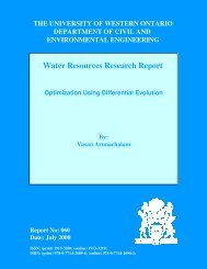
Figure 6. Uplift factors for 1g tests in dense sand and gravel.<br />
3.2.2 Dense sand and gravel<br />
Load-displacement plots are shown for <strong>the</strong><br />
laboratory tests in dense and loose sand and dense<br />
gravel in Figure 5. Tests were conducted with a pipe<br />
<strong>of</strong> diameter, D = 48 mm and an initial embedment<br />
ratio, H/D ≈ 3. There is a clear difference compared<br />
to <strong>the</strong> loose sand tests, with a peak uplift resistance,<br />
which drops quickly by half to a residual pull-out<br />
force. This residual force <strong>the</strong>n reduces as <strong>the</strong> pipe<br />
moves towards <strong>the</strong> surface. The pattern is reflected<br />
in <strong>the</strong> uplift factors (Figure 6). A peak uplift factor<br />
(fd ≥ 1) on initial movement <strong>the</strong>n reduces to values<br />
similar to <strong>the</strong> loose sample after a small pipe<br />
displacement. For <strong>the</strong> sand, <strong>the</strong> distance required to<br />
reach <strong>the</strong> residual value <strong>of</strong> fd is 5 mm, for gravel, it<br />
is 15 mm (see Figure 5). Fur<strong>the</strong>r experiments are<br />
needed to examine this behaviour for a wider range<br />
<strong>of</strong> H/D and soil types.<br />
3.2.3 Sand and gravel berms<br />
Uplift factors are shown against reducing<br />
embedment ratio for <strong>the</strong> tests with and without<br />
gravel or sand berms on loose, saturated sand in<br />
Figure 7. There is a clear increase in uplift resistance<br />
with ei<strong>the</strong>r a gravel or sand berm, but this is more<br />
marked with <strong>the</strong> gravel berm. Indeed, <strong>the</strong> increase in<br />
uplift resistance due to <strong>the</strong> gravel berm compared to<br />
pure loose sand increases with <strong>the</strong> displacement <strong>of</strong><br />
<strong>the</strong> pipe. This may be due to <strong>the</strong> rising soil surface<br />
due to <strong>the</strong> dilation <strong>of</strong> <strong>the</strong> angular gravel berm during<br />
pipe displacement, which ensures that <strong>the</strong> pipe burial<br />
is greater than calculated assuming H = Hi - δ.<br />
Uplift factor, fd<br />
2<br />
1.8<br />
1.6<br />
1.4<br />
1.2<br />
1<br />
0.8<br />
0.6<br />
0.4<br />
0.2<br />
Vertical slip model<br />
C4 (sand)<br />
C7 (sand)<br />
C8 (gravel berm)<br />
C9 (sand berm)<br />
0<br />
1 1.5 2 2.5 3 3.5 4 4.5<br />
3.3 Mobilisation <strong>of</strong> peak uplift load: initial loaddisplacement<br />
response<br />
3.3.1 Loose sand<br />
The initial load-displacement data for <strong>the</strong> tests on<br />
dry loose sand are shown in Figure 8. Uplift load<br />
(Wu) is normalised by <strong>the</strong> peak uplift load (Wumax)<br />
for each model test to allow comparison <strong>of</strong><br />
mobilisation distances. For <strong>the</strong> laboratory tests<br />
(when D = 32 mm or 48 mm), 90 % <strong>of</strong> peak uplift<br />
load was mobilised when pipe displacement, δ ≈ 0.5<br />
mm and <strong>the</strong> peak capacity was reached by about 1<br />
mm. However, <strong>the</strong> prototype displacement for 90%<br />
mobilisation in <strong>the</strong> centrifuge model tests was 3 or 4<br />
mm.<br />
If <strong>the</strong> displacement is fur<strong>the</strong>r normalised by<br />
embedment depth, H, <strong>the</strong> graph shown in Figure 9 is<br />
produced. There is good agreement between results<br />
for different pipe sizes in loose sand and it appears<br />
that 90% <strong>of</strong> <strong>the</strong> maximum uplift load is mobilised<br />
when δ/H ≈ 0.4 %. This agrees well with δ/H = 0.5<br />
% recommended by Matyas and Davies (1983) in<br />
<strong>the</strong>ir laboratory tests and δ/H = 1 % recommended<br />
by Trautman et al. (1985).<br />
3.3.2 Dense sand and gravel<br />
Normalised initial load-displacement behaviour from<br />
<strong>the</strong> laboratory tests in dense sand and gravel is also<br />
shown on Figure 9. Peak uplift load is mobilised<br />
within significantly smaller displacements than for<br />
loose sand. Fur<strong>the</strong>r centrifuge tests are required to<br />
ascertain how this scales with pipe size or<br />
embedment depth.<br />
Embedment Cover ratio, ratio, H/D H/D<br />
Figure 7. Uplift factors for loose, sat. sand with/without berms. Figure 9. Normalised load-displacement data.<br />
Load, Wu/Wumax.<br />
Load, Wu/Wumax.<br />
0.6<br />
L5 (D = 32mm)<br />
0.4<br />
Centrifuge tests<br />
L6 (D = 48 mm)<br />
0.2<br />
0<br />
C1 (D=48 mm)<br />
C2 (D=240 mm)<br />
-0.2<br />
0 1 2 3 4 5<br />
1<br />
0.8<br />
0.6<br />
0.4<br />
0.2<br />
-0.4<br />
0<br />
1.2<br />
1<br />
0.8<br />
1g tests<br />
Displacement, mm<br />
Figure 8. Load-displacement behaviour <strong>of</strong> pipes in loose sand<br />
L8 (dense sand)<br />
L13 (dense gravel)<br />
L6 (loose sand)<br />
C1 (loose sand)<br />
C3 (loose sand)<br />
C4 (loose sand)<br />
C7 (loose sand)<br />
C8 (gravel berm)<br />
C9 (sand berm)<br />
0 0.002 0.004 0.006 0.008 0.01 0.012 0.014<br />
Displacement/Embedment depth.