Manual for 125-150 lb. cartridge operated - Amerex Corporation
Manual for 125-150 lb. cartridge operated - Amerex Corporation
Manual for 125-150 lb. cartridge operated - Amerex Corporation

Create successful ePaper yourself
Turn your PDF publications into a flip-book with our unique Google optimized e-Paper software.
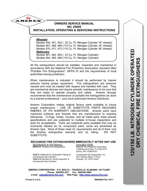
OWNERS SERVICE MANUAL<br />
NO. 05605<br />
INSTALLATION, OPERATING & SERVICING INSTRUCTIONS<br />
Wheeled<br />
Models 450, 451, 452 ( 25 Cu. Ft. Nitrogen Cylinder 16” wheels)<br />
Models 467, 468, 469 (110 Cu. Ft. Nitrogen Cylinder 16” wheels)<br />
Models 470, 471, 472 (110 Cu. Ft. Nitrogen Cylinder 36” wheels)<br />
Stationary<br />
Models 481, 482, 483 ( 23 Cu. Ft. Nitrogen Cylinder)<br />
Models 484, 485, 486 (110 Cu. Ft. Nitrogen Cylinder)<br />
All fire extinguishers should be installed, inspected and maintained in<br />
accordance with the National Fire Protection Association standard titled<br />
"Portable Fire Extinguishers", NFPA-10 and the requirements of local<br />
authorities having jurisdiction.<br />
When maintenance is indicated it should be per<strong>for</strong>med by trained<br />
persons having proper equipment. Fire extinguishers are pressure<br />
vessels and must be treated with respect and handled with care. They<br />
are mechanical devices and require periodic maintenance to be sure that<br />
they are ready to operate properly and safely. <strong>Amerex</strong> strongly<br />
recommends that the maintenance of portable fire extinguishers be done<br />
by a trained professional – your local authorized <strong>Amerex</strong> Distributor.<br />
<strong>Amerex</strong> <strong>Corporation</strong> makes original factory parts available to insure<br />
proper maintenance – USE OF SUBSTITUTE PARTS RELEASES<br />
AMEREX OF ITS WARRANTY OBLIGATIONS. <strong>Amerex</strong> parts have<br />
machined surfaces and threads that are manufactured to exacting<br />
tolerances. O-rings, hoses, nozzles, and all metal parts meet precise<br />
specifications and are subjected to multiple in-house inspections and<br />
tests <strong>for</strong> acceptability. There are substitute parts available that may be<br />
incorrectly labeled as UL component parts, some are advertised as<br />
<strong>Amerex</strong> type. None of these meet UL requirements and all of them void<br />
the <strong>Amerex</strong> extinguisher warranty and UL listing. DO NOT<br />
SUBSTITUTE.<br />
RECHARGE FIRE EXTINGUISHERS IMMEDIATELY AFTER ANY USE<br />
REFERENCES IN THIS MANUAL: AVAILABLE FROM:<br />
NFPA-10 Portable Fire Extinguishers National Fire Protection Association<br />
1 Batterymarch Park, P.O, Box 9101<br />
Quincy, MA 02269-9101<br />
CGA C-1 Methods <strong>for</strong> Hydrostatic Testing of Compressed Gas Association, Inc.<br />
Compressed Gas Cylinders 4221 Walney Road, 5 th Floor<br />
CGA C-6 Standard <strong>for</strong> Visual Inspection of<br />
Compressed Gas Cylinders<br />
Chantilly, VA 20151-2923<br />
AMEREX CORPORATION – P.O. BOX 81 – TRUSSVILLE, ALABAMA 35173-0081<br />
Phone: 205/655-3271 Fax: 800/654-5980<br />
e-mail: sales@amerex-fire.com Web Page: http://www.amerex-fire.com<br />
Printed in U.S.A. 0M05605H Rev.10/11<br />
<strong>125</strong>/<strong>150</strong> LB. NITROGEN CYLINDER OPERATED<br />
DRY CHEMICAL FIRE EXTINGUISHERS
INTRODUCTION<br />
THIS MANUAL IS ATTACHED TO EVERY NEW EXTINGUISHER SHIPPED FROM THE<br />
FACTORY. IT CONTAINS VALUABLE INFORMATION WHICH SHOULD BE STUDIED BY<br />
EVERYONE WHO WILL USE OR SERVICE THE EXTINGUISHER. THE MANUAL SHOULD<br />
BE STORED IN A CONVENIENT LOCATION FOR EASY REFERENCE.<br />
PREPARING YOUR NEW EXTINGUISHER FOR USE<br />
WARNING: THIS FIRE EXTINGUISHER IS SHIPPED FROM THE FACTORY EMPTY.<br />
AFTER INITIAL PREPARATIONS, CAREFULLY FOLLOW THE RECHARGING<br />
INSTRUCTIONS BEFORE PLACING IT INTO SERVICE.<br />
1. Remove all wrappings, straps and pallet retaining bolts.<br />
2. Examine the extinguisher <strong>for</strong> shipping damage. Check to make sure that you have received the<br />
dry chemical charges that are shipped with the extinguisher (ABC and PURPLE K (two) 2 - 50<br />
<strong>lb</strong>. pails and 1 (one) 25 <strong>lb</strong>. pail; REGULAR – three (3) 50 <strong>lb</strong>. pails).<br />
3. Fill the extinguisher by carefully following the Recharge instructions.<br />
4. Remove the nitrogen cylinder protective shipping cap. Save the cap as it must be installed<br />
whenever a charged nitrogen cylinder is transported. Remove temporary (shipping) ring pin and<br />
install large ring pin.<br />
5. Install new lockwire seal. Check the nitrogen cylinder pressure. The gauge should read<br />
approximately 2015 psig (13.9 mPa) at 70ºF (21ºC) ambient temperature. See the<br />
"Troubleshooting Guide" <strong>for</strong> pressure-temperature allowances. The lockwire seal should be<br />
intact.<br />
6. Remove (and save) the Safety Vent Plug installed on all "T" handle nitrogen valves. Connect<br />
the nitrogen supply hose firmly to the nitrogen cylinder valve. Make sure that there are no kinks<br />
in this hose.<br />
7. Disconnect the discharge hose assembly from the agent cylinder. Make sure that the hose and<br />
nozzle are unobstructed and that the Moisture Seal is undamaged and properly seated on the<br />
agent cylinder discharge fitting. Reconnect the discharge hose to the agent cylinder and with<br />
the nozzle in the closed (<strong>for</strong>ward) position, place it on the storage rack. (See Page 11 )<br />
8. Record the date the unit is being placed into service on the inspection tag and attach it to the<br />
extinguisher.<br />
9. Remove the caution (not charged) tag.<br />
1
INSTALLATION<br />
WARNING: DO NOT PLACE THIS EXTINGUISHER CLOSE TO A POTENTIAL FIRE<br />
Do not place this extinguisher close to a potential fire hazard. <strong>Amerex</strong> recommends location no<br />
less than a 50 foot distance from the hazard while leaving an unobstructed access. Avoid placing it<br />
in an extremely hot or cold place. The operational temperature range <strong>for</strong> this extinguisher is -<br />
65°F to +120°F (-54°C to +49°C). The extinguisher should be adequately protected if temperatures<br />
outside of this range are anticipated. Keep the extinguisher clean and free from dirt, ice, chemicals<br />
and any contaminants that may interfere with its proper operation. DO NOT FUNCTIONALLY<br />
TEST THIS FIRE EXTINGUISHER. (Testing or any use may cause the extinguisher to gradually<br />
lose pressure over a period of time and make the extinguisher ineffective.)<br />
OPERATION<br />
NOTE: Persons expected to use this extinguisher should be trained in initiating its<br />
operation and in the proper fire fighting technique. Familiarize all personnel with<br />
this in<strong>for</strong>mation be<strong>for</strong>e an emergency occurs.<br />
1. Move the extinguisher to within approximately 50 feet of the fire site and keep extinguisher<br />
upright. Remove ring (safety) pin and pull "T" handle to open argon cylinder valve. This will<br />
pressurize the extinguisher.<br />
2. Remove nozzle from the mount, and with the nozzle lever in the closed position, pull hose from<br />
rack.<br />
3. Start back 20 feet from the fire and aim at base of fire nearest you.<br />
4. Open hose and nozzle firmly and be prepared <strong>for</strong> discharge recoil. Open nozzle by pulling the<br />
handle fully toward you. Slowly sweep side to side across the base of the fire and past both<br />
edges. Progressively follow up until the fire is extinguished.<br />
DISCHARGE TIME (APPROXIMATE) - See extinguisher nameplate (label)<br />
EFFECTIVE RANGE OF THE AGENT THROW - 25 to 40 feet<br />
HOSE LENGTH – 50 feet<br />
RECHARGE FIRE EXTINGUISHERS IMMEDIATELY AFTER ANY USE<br />
SHUTDOWN<br />
1. After making sure that the fire has been completely extinguished, close the nozzle valve and<br />
then close nitrogen cylinder valve (push “T” handle to closed position). Wheeled Extinguisher<br />
– Tip over until it rests on both wheels and handle (in this position much of the remaining<br />
chemical will stay in the cylinder). Stationary Extinguisher – see instructions below.<br />
2. Open the nozzle valve slowly to clear the hose of any remaining pressure and chemical (be<br />
prepared <strong>for</strong> recoil and discharge of agent).<br />
WARNING: MAKE SURE THAT ALL PRESSURE HAS ESCAPED BEFORE ANY FURTHER<br />
DISASSEMBLY.<br />
3. Stand unit upright after complete depressurization.<br />
NOTE: Nitrogen pressure in the agent cylinder cannot escape through a disconnected nitrogen<br />
hose assembly due to a check valve in the system. Always be careful when removing<br />
the fill cap.<br />
4. Coil the extinguisher hose onto the storage rack and position the nozzle onto the mount in<br />
preparation <strong>for</strong> transport to the recharge location.<br />
CAUTION: DO NOT TRANSPORT A NITROGEN CYLINDER WITHOUT INSTALLING THE<br />
PROTECTIVE SHIPPING CAP.<br />
2
VENTING DEVICE<br />
(Standard on all Stationary Extinguishers, Optional on Wheeled Extinguishers)<br />
A venting device has been installed on all stationary extinguishers to provide a means of safely<br />
and easily relieving residual argon pressure from the agent cylinder while utilizing the same<br />
pressure to evacuate or "blow down" the hose.<br />
See Below: Figure 1 – Models 484, 485 & 486 (Tall Units – 110 cu. ft. Nitrogen Cylinder)<br />
Figure 2 – Models 481, 482 & 483 (Short Units – 23 cu. ft. Nitrogen Cylinder)<br />
OPERATION – After the fire has been successfully extinguished and it has been<br />
determined that it is completely out:<br />
1. Confirm that the nozzle lever is in the CLOSED position.<br />
2. Close the argon valve (move "T" handle to CLOSED position)<br />
3. Remove ring pin and CLOSE agent cylinder valve (Valve A in Fig. 1) to prevent further<br />
chemical from entering the hose.<br />
4. Remove ring pin and OPEN pressure vent valve (Valve B in Fig. 1) to allow argon gas to<br />
by-pass the chemical and pressurize the hose.<br />
5. Open discharge nozzle to vent all residual chemical and nitrogen gas pressure.<br />
6. Re-open nitrogen valve if additional pressure is required.<br />
7. When recharging this unit, reset agent cylinder and vent valves, install ring pins and<br />
lockwire seals.<br />
Figure 1 Figure 2<br />
CAUTION: VALVE SHUT-OFF HANDLES MUST BE IN<br />
THE POSITIONS SHOWN WHEN EXTINGUISHER IS<br />
ON STANDBY OR IN ACTUAL OPERATION.<br />
3
AMEREX CORPORATION DOES NOT SERVICE, MAINTAIN OR RECHARGE FIRE<br />
EXTINGUISHERS. THIS MANUAL IS PUBLISHED AS A GUIDE TO ASSIST QUALIFIED<br />
SERVICE PERSONNEL IN THE INSPECTION, MAINTENANCE AND RECHARGE OF AMEREX<br />
FIRE EXTINGUISHERS ONLY. NO INSTRUCTION MANUAL CAN ANTICIPATE ALL POSSIBLE<br />
MALFUNCTIONS THAT MAY BE ENCOUNTERED IN THE SERVICE OF FIRE<br />
EXTINGUISHERS. DUE TO THE POSSIBILITY THAT PRIOR SERVICE PERFORMED ON THIS<br />
EQUIPMENT MAY HAVE BEEN IMPROPERLY DONE, IT IS EXTREMELY IMPORTANT THAT<br />
ALL WARNINGS, CAUTIONS AND NOTES IN THIS MANUAL BE CAREFULLY OBSERVED.<br />
FAILURE TO HEED THESE INSTRUCTIONS COULD RESULT IN SERIOUS INJURY.<br />
AMEREX ASSUMES NO LIABILITY FOR SERVICE, MAINTENANCE OR RECHARGE OF FIRE<br />
EXTINGUISHERS BY PUBLISHING THIS MANUAL.<br />
INSPECTING THE EXTINGUISHER<br />
NFPA 10 - This extinguisher should be inspected at regular intervals (monthly or more often if<br />
circumstances dictate) to insure that it is ready <strong>for</strong> use. (NFPA 10) Inspection is a "quick check" that a<br />
fire extinguisher is available and is in operating condition. It is intended to give reasonable assurance<br />
that the fire extinguisher is fully charged. This is done by verifying that it is in its designated place, that<br />
it has not been actuated or tampered with, and that there is no obvious physical damage or condition to<br />
prevent its operation.<br />
PERIODIC INSPECTION PROCEDURES (Monthly or more often if circumstances dictate) A “quick<br />
check” should be made of the extinguisher <strong>for</strong> the following:<br />
1. Located in designated place.<br />
2. No obstructions to access or visibility.<br />
3. Operating instructions on nameplate and facing outward.<br />
4. Seals and tamper indicators not broken or missing.<br />
5. Determine fullness by weighing (full weight is noted on the nameplate [label]).<br />
6. Examine <strong>for</strong> obvious physical damage, corrosion, leakage or clogged nozzle.<br />
7. Pressure gauge (nitrogen cylinder) reading in operable area.<br />
8. Condition of tires & wheels, carriage, hose and nozzle.<br />
MAINTENANCE<br />
At least once a year or more frequently if circumstances require, maintenance should be per<strong>for</strong>med.<br />
Maintenance is a "thorough check" of the extinguisher. It is intended to give maximum assurance that<br />
a fire extinguisher will operate effectively and safely. It includes a thorough examination <strong>for</strong> physical<br />
damage or condition to prevent its operation and any necessary repair or replacement. It will normally<br />
reveal if hydrostatic testing.<br />
NOTE: NFPA-10 spells out wheeled extinguisher maintenance procedures. NFPA requires that<br />
regulators on wheeled extinguishers be checked annually to meet manufacturer’s “dead set”<br />
and “minimum flow” recommendations. This in<strong>for</strong>mation is provided in a special section on<br />
page 6 (R-a thru R-d) <strong>for</strong> <strong>Amerex</strong> Regulated Wheeled Models 467, 468, 469, 470, 471 & 472<br />
and Regulated Stationary Models 484, 485 and 486.<br />
NOTE: The Getz Manufacturing Universal Wheeled Extinguisher Service Kit is available so that NFPA-<br />
10 required maintenance functions can be per<strong>for</strong>med.<br />
4
ANNUAL MAINTENANCE – SERVICE PROCEDURE<br />
WARNING: BEFORE SERVICING, BE SURE THE EXTINGUISHER AGENT CYLINDER IS NOT<br />
PRESSURIZED. THIS PROCEDURE IS BEST ACCOMPLISHED WITH THE<br />
EXTINGUISHER IN AN UPRIGHT POSITION AND ON A LEVEL SURFACE.<br />
1. Clean extinguisher to remove dirt, grease or <strong>for</strong>eign material. Check to make sure that the<br />
instruction nameplate is securely fastened and legible. Inspect the cylinders <strong>for</strong> corrosion,<br />
abrasion, dents or weld damage. If any damage is found, hydrostatically test in accordance with<br />
instructions in CGA C-1 and C-6 and NFPA 10.<br />
2. Inspect the extinguisher <strong>for</strong> damaged, missing or substitute parts. A careful inspection should<br />
be made of the safety relief (MODELS 450, 451 & 452) to make sure that it has not ruptured,<br />
corroded or been tampered with. ONLY FACTORY REPLACEMENT PARTS ARE APPROVED<br />
FOR USE ON AMEREX FIRE EXTINGUISHERS.<br />
3. Check the date of manufacture printed on the extinguisher label (nameplate) or on the agent<br />
cylinder dome. The agent cylinder, the discharge hose assembly and nitrogen supply hose<br />
must be hydrostatically tested every 12 years. Test pressure:<br />
a. Agent Cylinder – 500 psi (3447 kPa)<br />
b. Hose Assembly – 300 psi (2068 kPa)<br />
4. Check the hydrostatic test date on the crown of the nitrogen cylinder. The nitrogen cylinder<br />
must be retested in accordance with DOT regulations.<br />
5. Check the gauge on the nitrogen cylinder. If the pressure is below 1700 psig (11.7 mPa)<br />
repressurize the cylinder to 2015 psig (13.9 mPa) or replace it. A low gauge pressure may<br />
indicate leakage. Check <strong>for</strong> leaks. A low gauge reading may also result from low temperature.<br />
See the temperature/pressure relationship chart in the Troubleshooting Guide. Check the<br />
tamper indicator (lockwire seal) on the argon valve and replace if necessary.<br />
6. Wheeled extinguishers – Inspect the wheels to insure they rotate freely. Lubricate as required.<br />
WARNING: THE FOLLOWING STEPS SHOULD ONLY BE PERFORMED BY<br />
PROFESSIONALLY TRAINED AND QUALIFIED SERVICE PERSONNEL THOROUGHLY<br />
FAMILIAR WITH INDUSTRY SERVICE PROCEDURES AND SAFETY PRECAUTIONS AND<br />
HAVING THE NECESSARY EQUIPMENT TO PERFORM THE SERVICE PROPERLY. ALL<br />
EXTINGUISHER AND SERVICE EQUIPMENT COMPONENTS, FITTINGS AND ADAPTERS<br />
MUST BE IN GOOD CONDIITON AND PROPERLY CONNECTED.<br />
5
MAINTENANCE OF REGULATED WHEELED EXTINGUISHERS<br />
NOTE: Steps R-a thru R-d apply to models with a Regulator. These procedures should be per<strong>for</strong>med only by<br />
professionally trained and qualified service personnel thoroughly familiar with industry service procedures<br />
and safety precautions. All extinguisher and service equipment components, fittings and adapters must<br />
be in good condition and properly connected.<br />
R-a. Disconnect the regulator from the agent cylinder. Visually examine the regulator and high pressure hose<br />
<strong>for</strong> signs of damage, corrosion or deterioration. To per<strong>for</strong>m the regulator static pressure, dead set and<br />
minimum pressure flow rate checks. Connect the proper hose service kit Adapter (P/N 01740) to the low<br />
pressure outlet port of the regulator. Connect the service kit Hose Assembly (P/N 01410) and Flow<br />
Chamber (P/N 0<strong>125</strong>0) to the regulator low pressure port adapter.<br />
R-b. Make sure all service kit connections are secure and that the kit flow chamber valve is closed. Check<br />
nitrogen cylinder pressure to ensure that it is within the acceptable operating pressure range. Hold the kit<br />
flow chamber in one hand and slowly open the nitrogen cylinder (with either the “T” handle operating lever<br />
or by turning the handwheel if so equipped). Observe flow chamber pressure reading to see if it is within<br />
the specified static dead set pressure parameters noted below. The only type regulators used on <strong>Amerex</strong><br />
dry chemical regulated wheeled extinguishers were Victor and MECO. Also see <strong>Amerex</strong> Tech Tip <strong>for</strong><br />
Class D Dry Powder Wheeled Extinguisher Pressures.<br />
Regulator Type Model No. Static Dead Set Pressure Minimum Flow Pressure<br />
Victor SR-450L 225 – 245 psi 140 psi<br />
MECO P-600 235 – 255 psi 140 psi<br />
Victor SR-450E 225 – 245 psi 140 psi<br />
WARNING: IF THE PRESSURE READING EXCEEDS THE GIVEN PARAMETERS, QUICKLY<br />
CLOSE THE NITROGEN CYLINDER “T” HANDLE OR HANDWHEEL VALVE AND VENT THE<br />
PRESSURE BY OPENING THE FLOW CHAMBER BALL VALVE. REGULATORS CANNOT<br />
BE FIELD ADJUSTED – THEY MUST BE REPLACED IF FOUND TO BE OUT OF<br />
TOLERANCE.<br />
R-c. Observe the proper regulator static dead set pressure <strong>for</strong> a minimum of one minute – then fully open the<br />
flow chamber valve <strong>for</strong> 1-2 seconds and observe the pressure reading to ensure that the flow pressure<br />
does not drop below the minimum specified. Close the nitrogen cylinder valve after the test and vent the<br />
flow chamber pressure by opening the flow chamber valve.<br />
NOTE: Prior to per<strong>for</strong>ming minimum flow check, make sure that the nitrogen cylinder valve (“T” handle or<br />
handwheel) is FULLY OPEN so that it does not restrict or alter the flow readings.<br />
R-d Disconnect the service kit quick connect adapter from the low pressure regulator and reinstall the<br />
regulator securely to the agent cylinder. (THIS STEP IS FOR REGULATED EXTINGUISHERS ONLY)<br />
7. Disconnect the discharge hose from the agent cylinder. Check the couplings, hose and hose<br />
gaskets <strong>for</strong> damage or deterioration – replace as necessary.<br />
8. To per<strong>for</strong>m an operational integrity check on the discharge hose and nozzle combination:<br />
a. Connect the test kit hose adapter to the female end of the discharge hose.<br />
b. Connect the discharge nozzle shut-off lever and properly secure it.<br />
c. Connect a properly regulated and verified nitrogen pressure source (set to the<br />
extinguisher operating pressure (235-245 psi) to the test kit hose adapter.<br />
d. Slowly pressurize the discharge hose/nozzle assembly to the extinguisher operating<br />
pressure and check <strong>for</strong> leaks or distortion.<br />
6
e. Operate the nozzle lever to ensure proper operation and to clear the hose of any<br />
obstructions (if hose is obstructed – refer to Troubleshooting section of this manual.<br />
f. Close the nitrogen pressure source and slowly relieve remaining pressure by fully operating the<br />
nozzle lever.<br />
9. Remove the agent cylinder cap and examine it closely <strong>for</strong> any signs of damage, cracks or<br />
thread wear. Clean the agent cylinder fill cap threads and thread vent port on the cap with a stiff<br />
bristle nylon brush. Remove the fill cap gasket and check <strong>for</strong> wear, cracks or tears – replace if<br />
necessary. Lightly lubricate the gasket with Visilox and reinstall.<br />
10. Examine the dry powder agent <strong>for</strong> proper type and condition. Replace chemical that is<br />
contaminated, caked or other than the type indicated on the nameplate (label). Do not trust the<br />
height of the chemical in the cylinder when determining agent fill. Dry powder settles and the<br />
only true indication of agent fill is to weigh the extinguisher and compare with the weight<br />
indicated on the nameplate (label).<br />
11. Place the service kit Vent Spacer on top of the agent cylinder fill opening collar. Check again to<br />
see that the fill cap thread vent is clean and that the agent fill cap gasket is in place. Install the<br />
agent fill cap securely over the vent spacer. Record service data on the extinguisher inspection<br />
tag.<br />
CAUTION: (STEP 12) The agent cylinder cap threads must be clear and the cap securely<br />
installed onto the vent spacer and agent cylinder to allow pressure to slowly vent after<br />
per<strong>for</strong>ming the siphon tube clearing and gas tube integrity checks.<br />
12. To per<strong>for</strong>m a siphon tube clearing and gas tube integrity check:<br />
a. Remove the service kit Agent Hose Adapter from the discharge hose assembly and<br />
install it securely onto the agent cylinder siphon tube outlet.<br />
b. Using a regulated argon pressure source set to the extinguisher operating pressure (110<br />
psi), slowly and briefly pressurize the agent cylinder (the siphon tube should be clear<br />
within a couple of seconds and the agent cylinder pressure slowly vent from the<br />
fill cap thread vent). Pressure and/or dry chemical agent leaks from the gas tube inlet<br />
port (where the hose connects) will indicate a defective gas tube and will require that the<br />
agent cylinder be emptied and the gas tube replaced.<br />
c. Close the argon pressure source and allow all pressure to slowly vent from the thread<br />
vent port on the fill cap.<br />
d. AFTER ALL PRESSURE HAS BEEN RELIEVED, SLOWLY OPEN THE FILL CAP AND<br />
REMOVE THE TEST KIT VENT SPACER.<br />
e. Re-examine the agent to determine if any obstructions were cleared from the siphon<br />
tube and have risen to the surface.<br />
f. Clean the fill cap and agent cylinder thread surfaces. Securely install the fill cap gasket<br />
and fill cap.<br />
NOTE: THIS STEP (R-d.) IS FOR REGULATED EXTINGUISHERS ONLY<br />
R-d. Disconnect the service kit quick connector adapter from the low pressure port of the<br />
regulator and reinstall the regulator securely to the agent cylinder.<br />
7
13. Disconnect the high pressure hose from the argon cylinder valve. Securely install the service kit<br />
Argon/Nitrogen Cylinder Pressure Check Gauge Assembly to the nitrogen cylinder valve outlet<br />
and verify the indicated cylinder gauge pressure. Argon pressure should con<strong>for</strong>m to the<br />
temperature correction chart provided in the Troubleshooting section of this manual. Close the<br />
nitrogen cylinder valve and disconnect the Pressure Check Gauge Assembly.<br />
WARNING: IF THE NITROGEN CYLINDER VALVE HAS A "T" HANDLE QUICK OPENING<br />
OR A HANDWHEEL QUICK OPENING TRIP RELEASE, THE SAFETY VENT PLUG<br />
SHIPPED WITH THE EXTINGUISHER, OR THE TEST KIT SAFETY VENT PLUG MUST BE<br />
INSTALLED TO PROTECT SERVICE PERSONNEL FROM A HIGH VELOCITY DISCHARGE<br />
IN CASE THE LEVER IS ACCIDENTALLY OPENED.<br />
14. Install a new <strong>Amerex</strong> Moisture Seal per instructions in the package. Securely connect the<br />
discharge hose to the extinguisher. When assembling the hose to the agent cylinder or<br />
nozzle to the hose, tighten the coupling ¼ turn after contacting the hose gasket.<br />
15. Coil the hose on to the extinguisher hose rack using the Reverse Loop Procedure (see<br />
instructions in this manual). Install shut-off nozzle (and/or extension wand) with the lever in the<br />
Closed (<strong>for</strong>ward) position into the nozzle mount.<br />
16. Remove the safety vent plug from the argon cylinder. Reconnect the high pressure hose<br />
securely to the nitrogen cylinder valve. Wipe the extinguisher clean. Record service data on<br />
the inspection tag according to NFPA-10 requirements and attach to extinguisher. Return<br />
extinguisher to its proper location.<br />
RECHARGE<br />
NFPA 10 – Recharging is the replacement of the extinguishing agent and also includes the<br />
expellant <strong>for</strong> this type of extinguisher.<br />
RECHARGING PROCEDURE<br />
WARNING: BEFORE ATTEMPTING TO RECHARGE, BE SURE THIS EXTINGUISHER IS<br />
COMPLETELY DEPRESSURIZED. THERE IS A CHECK VALVE IN THE SYSTEM<br />
WHICH PREVENTS ARGON PRESSURE FROM ESCAPING FROM THE AGENT<br />
CYLINDER WHEN THE ARGON HOSE IS DISCONNECTED. THE AGENT<br />
CYLINDER MAY BE PRESSURIZED EVEN THOUGH NO PRESSURE ESCAPES<br />
FROM THE CYLINDER ARGON CONNECTION.<br />
NOTE: Proper procedure <strong>for</strong> recharging any dry chemical extinguisher includes the use of a<br />
“closed recovery system (NFPA-10). The Getz Model SV1 400 VACU-FILL SYSTEM is<br />
ideal <strong>for</strong> this application – it provides <strong>for</strong> the recovery of the remaining agent by direct<br />
discharge into the system, trapping the “fines” while allowing the nitrogen to escape and<br />
provides a more accurate fill of the extinguisher.<br />
IF A “CLOSED RECOVERY SYSTEM” IS NOT AVAILABLE PROCEED AS<br />
FOLLOWS:<br />
1. To depressurize:<br />
a. Close the argon cylinder valve.<br />
8
. Carefully tip extinguisher over until it rests on both wheels and handle. (In this<br />
position much of the agent will remain in the cylinder).<br />
c. Open nozzle valve slowly to clear hose of any remaining pressure and chemical (be<br />
prepared <strong>for</strong> a recoil and discharge of agent).<br />
d. Insure that all pressure has escaped be<strong>for</strong>e further disassembly.<br />
e. Stand extinguisher upright after complete depressurization.<br />
2. Complete items 1-6 of Maintenance Procedures. Carefully remove the fill cap. Detach<br />
discharge hose from the agent cylinder and the nozzle assembly from the hose. Blow out<br />
any chemical remaining in the hose. While per<strong>for</strong>ming this procedure, all parts and seals<br />
should be cleaned, inspected and replaced where necessary.<br />
3. Remove shutoff nozzle assembly from discharge hose and clean thoroughly. Check to<br />
make sure that the valve is closed when the lever is in the <strong>for</strong>ward position (toward the<br />
nozzle tip).<br />
4. Detach hose from nitrogen cylinder, install the shipping cap, unscrew the wing nuts and<br />
remove the nitrogen cylinder from the extinguisher.<br />
5. Remove the 50 ft. discharge hose from the storage rack and disconnect the hose from the<br />
agent cylinder fitting. Blow out any dry chemical agent remaining in the hose. clean hose –<br />
remove and discard the clear hose gasket from the female coupling.<br />
6. Remove remainder of ruptured moisture seal from the agent cylinder fitting. Replace with<br />
new Moisture Seal Assembly. Carefully follow the installation instructions contained in<br />
the Moisture Seal Assembly package, including the installation of a new clear hose<br />
gasket in the female hose coupling.<br />
7. Remove the agent cylinder fill cap and gasket. Clean fill cap threads and vent port, lubricate<br />
the cap gasket and set parts aside. Check the condition and type of any remaining chemical<br />
(replace any dry chemical that is contaminated or caked). Fill extinguisher with the type and<br />
amount of dry chemical shown on the extinguisher label – verify gross weight. Clean agent<br />
cylinder collar threads. Install the fill cap and tighten securely.<br />
WARNING: DO NOT OVERFILL THE EXTINGUISHER. THIS COULD CAUSE A<br />
MALFUNCTION. DO NOT MIX TYPES OF AGENTS – THIS CAN CAUSE A<br />
DANGEROUS PRESSURE BUILD UP AND REDUCE EXTINGUISHER<br />
EFFECTIVENESS.<br />
8. Install the proper nitrogen cylinder (pressurized to 2015 psi), remove the shipping cap, place<br />
on the extinguisher and attach the nitrogen hose. Nitrogen cylinders with “T” handle<br />
quick opening valve: Remove small temporary ring (safety) pin and install large ring pin.<br />
Install a lockwire seal (tamper indicator). Nitrogen cylinders with handwheel or lever<br />
actuated quick opening valve: Leadwire seal must be installed<br />
9. Reattach the discharge hose to the extinguisher (tighten hand tight plus a ¼ turn). Properly<br />
coil the hose onto the storage rack (see page 11). Reattach the shutoff nozzle firmly to the<br />
hose and store it in the mount with the shutoff lever in the closed (<strong>for</strong>ward) position.<br />
10. Record the service date on the inspection tag and place the extinguisher in its proper<br />
location.<br />
9
TROUBLESHOOTING GUIDE<br />
WARNING: BEFORE ATTEMPTING TO CORRECT ANY LEAKAGE PROBLEM, BE SURE THAT<br />
THE AGENT CYLINDER IS COMPLETELY DEPRESSURIZED. Always use caution when opening<br />
the shutoff nozzle or any other connection as a leaking nitrogen cylinder valve seat may have<br />
pressurized the agent container refer to the recharge procedure <strong>for</strong> proper method of<br />
depressurization.<br />
1.<br />
2.<br />
3.<br />
4.<br />
5.<br />
6.<br />
7.<br />
PROBLEM CORRECTIVE ACTION<br />
Nitrogen cylinder gauge<br />
reads low or high<br />
Nitrogen pressure is too low.<br />
Valve is closed. Tamper seal<br />
is intact. There is pressure in<br />
the agent and nitrogen<br />
cylinders.<br />
Nitrogen pressure is too low.<br />
Valve is closed. Tamper seal<br />
is intact. No pressure<br />
observed<br />
cylinder.<br />
in the agent<br />
Shutoff nozzle does not move<br />
freely.<br />
Unable to remove the agent<br />
cylinder cap.<br />
Nitrogen hose cut, cracked or<br />
abraded.<br />
Chemical agent and pressure<br />
leaking from the safety disc<br />
assembly. (Models 450, 451,<br />
452)<br />
Temperature may have affected the pressure reading<br />
Temperature (F) 35º 70º 120º<br />
Temperature (C) 2º 21º 49º<br />
Recommended Pressure<br />
psig 1880 2015 2200<br />
mPa 13.0 13.9 15.2<br />
Minimum Pressure<br />
psig 1590 1700 1900<br />
mPa 11.0 11.7 13.1<br />
NO CORRECTIVE ACTION IS REQUIRED IF THE<br />
PRESSURE IS WITHIN PARAMETERS STATED ABOVE.<br />
Valve seat has leaked and has pressurized the agent<br />
cylinder. Follow Recharge Procedure <strong>for</strong> restoring the<br />
extinguisher to service.<br />
Leakage in the nitrogen valve at other than the valve seal.<br />
Replace with a properly charged nitrogen cylinder.<br />
Disassemble, clean and lubricate.<br />
Agent cylinder may be pressurized. Make no further attempt<br />
to remove the cap until this is checked. See the Recharge<br />
Procedure <strong>for</strong> proper depressurization method.<br />
Replace hose assembly.<br />
Inspect safety outlet <strong>for</strong> tightness or damage. Tighten if<br />
necessary.<br />
NOTE: Only tighten the large hex nut of the assembly. The<br />
small round nut containing the holes is factory set to a<br />
specific torque value. Do not attempt to adjust. If damaged<br />
or ruptured, replace complete <strong>Amerex</strong> Safety Disc<br />
Assembly.<br />
10
1<br />
Connect hose coupling to outlet on<br />
the extinguisher. Lay hose straight<br />
on ground to its full 25 ft. length.<br />
Start first regular loop counterclockwise<br />
by placing between side<br />
brackets and over the top bracket.<br />
2<br />
The second loop is a REVERSE<br />
loop. Notice that the hose passes<br />
behind the loop on this reverse<br />
loop. If instructions are<br />
followed, the hose will uncoil<br />
without kinks.<br />
3<br />
The next loop is a regular "hose in<br />
front" loop. Succeeding loops are<br />
alternated: reverse, front, reverse,<br />
etc. <strong>for</strong> six full loops.<br />
4<br />
Adjust the loops so that the nozzle<br />
or extension wand fits into the<br />
nozzle mount. Loops should be<br />
approximately the same size.<br />
Guide to Proper Installation of Hose on<br />
Wheeled or Stationary Fire Extinguishers<br />
11
Item<br />
No.<br />
Part<br />
No.<br />
PARTS LIST<br />
<strong>for</strong><br />
<strong>125</strong>/<strong>150</strong> <strong>lb</strong>. Wheeled & Stationary<br />
Dry Chemical Extinguishers<br />
110 Cu. Ft. Nitrogen Cylinder<br />
WHEELED MODELS<br />
467 <strong>125</strong> LB. ABC, 16” WHEELS 470 <strong>125</strong> LB. ABC, 36” WHEELS<br />
468 <strong>150</strong> LB. REGULAR, 16” WHEELS 471 <strong>150</strong> LB. REGULAR, 36” WHEELS<br />
468 <strong>125</strong> LB. PURPLE K, 16” WHEELS 472 <strong>125</strong> LB. PURPLE K, 36” WHEELS<br />
Std.<br />
Pkg.<br />
1<br />
1 06993<br />
Description<br />
Cap (Chrome Plated Brass), Agent<br />
Cylinder<br />
1A <strong>125</strong>76<br />
Cap (Chrome Plated Brass), Agent<br />
Cylinder w/Pressure Indicator<br />
1<br />
2 02272 Gasket, Cap 1<br />
3 13958 Bumper,Rrubber 12<br />
4 02235 Nitrogen Pressure Regulator 1<br />
5A 12467<br />
Nitrogen Valve with Gauge<br />
(“T” Handle Quick Release)<br />
1<br />
5B 06373 Valve Lever (“T” Handle-Complete) 1<br />
5C 10213 Gauge – 3000 psi 1<br />
5D 09897 Valve Stem Assembly 6<br />
5E 00501 Spring 6<br />
6 04128<br />
Nitrogen Cylinder (110 cu.ft.)-<br />
Charged with Cap, Valve & Gauge<br />
1<br />
7 02234 Nitrogen Hose Assembly 1<br />
8 11024 Retaining Strap w/Hose Hanger 1<br />
9 11021<br />
Retaining Strap (Bottom) – Nitrogen<br />
Cylinder<br />
1<br />
10 16483 Bolt, Washer & Wing Nut 1<br />
11<br />
07485<br />
07484<br />
Pictogram-467,470, 485<br />
Pictogram-468,469,471,472,486,487<br />
1<br />
12<br />
07025<br />
Wheel Asy – 36” x 2 ½” w/rubber<br />
tread<br />
1<br />
07389 Hub Cap w/hardware – 36” Wheels 1<br />
13 07751<br />
Wheel Asy – 16” with Hub Cap,<br />
Washer & Retaining Pin (Semi-Pneu)<br />
1<br />
14 04945 Hub Cap – 16” Wheels 1<br />
15 07411 Moisture Seal 1<br />
16 03877 Gasket, Hose/Nozzle 6<br />
17 06279 Ball Valve Assembly 1<br />
18 06032 Nozzle Tip (.265) 1<br />
19 03501 Hose Assembly, 50’ 1<br />
20 07574 Nozzle Assembly (Ball Valve & Tip) 1<br />
21 04892 Hydrotest Adapter (Nitrogen Cylinder) 1<br />
22<br />
09857<br />
05723<br />
Fill Adapter<br />
Hydrotest Adapter (Hose)<br />
1<br />
1<br />
* 06247 Visilox Lubricant (5 oz. tube) 1<br />
* PART NOT PICTURED<br />
STATIONARY MODELS<br />
485 <strong>125</strong> LB. ABC<br />
486 <strong>150</strong> LB. REGULAR<br />
487 <strong>125</strong> LB. PURPLE K<br />
12
Item<br />
No.<br />
Part<br />
No.<br />
Std.<br />
Pkg.<br />
1 06993<br />
Description<br />
Cap (Chrome Plated Brass), Agent<br />
Cylinder<br />
1<br />
1A <strong>125</strong>76<br />
Cap (Chrome Plated Brass), Agent<br />
Cylinder w/Pressure Indicator<br />
1<br />
2 02272 Gasket, Cap 1<br />
3 03787 Safety Disc Assembly 1<br />
4 03818 Nitrogen Hose Assembly 1<br />
5 01990 Rubber Bumper 12<br />
6A 12467<br />
Nitrogen Valve with Gauge<br />
(“T” Handle Quick Release)<br />
1<br />
6B 06373 Valve Lever (“T” Handle-Complete) 1<br />
6C 10213 Gauge – 3000 psi 1<br />
6D 09897 Valve Stem Assembly 6<br />
6E 00501 Spring 6<br />
7 03817<br />
Nitrogen Cylinder (23 cu.ft.)-Charged<br />
with Cap, Valve & Gauge<br />
1<br />
8 04072 Saddle Clamp WUS 1<br />
9 16483 Bolt, Washer & Wing Nut 1<br />
10<br />
07485<br />
07484<br />
Pictogram-450<br />
Pictogram-451, 452<br />
1<br />
11 07751<br />
Wheel Asy – 16” with Hub Cap,<br />
Washer & Retaining Pin (Semi-Pneu)<br />
1<br />
12 04945 Hub Cap – 16” Wheels 1<br />
13 07411 Moisture Seal 1<br />
14 03877 Gasket, Hose/Nozzle 6<br />
15 06279 Ball Valve Assembly 1<br />
16 06032 Nozzle Tip (.312) 1<br />
17 03501 Hose Assembly, 50’ 1<br />
18 07574 Nozzle Assembly (Ball Valve & Tip) 1<br />
19 04892 Hydrotest Adapter (Nitrogen Cylinder) 1<br />
20<br />
09857<br />
05723<br />
Fill Adapter<br />
Hydrotest Adapter (Hose)<br />
1<br />
1<br />
* 06247 Visilox Lubricant (5 oz. tube) 1<br />
* PART NOT PICTURED<br />
PARTS LIST<br />
<strong>for</strong><br />
<strong>125</strong>/<strong>150</strong> <strong>lb</strong>. Wheeled & Stationary<br />
Dry Chemical Extinguishers<br />
23 Cu. Ft. Nitrogen Cylinder<br />
WHEELED MODELS STATIONARY MODELS<br />
450 <strong>125</strong> LB. ABC 481 <strong>125</strong> LB. ABC<br />
451 <strong>150</strong> LB. REGULAR 482 <strong>150</strong> LB. REGULAR<br />
452 <strong>125</strong> LB. PURPLE K 483 <strong>125</strong> LB. PURPLE K<br />
13