OEM Equipment - PROMELSA
OEM Equipment - PROMELSA
OEM Equipment - PROMELSA

Create successful ePaper yourself
Turn your PDF publications into a flip-book with our unique Google optimized e-Paper software.
<strong>OEM</strong> <strong>Equipment</strong><br />
Four-Position Sectionalizing<br />
Loadbreak Switches<br />
GENERAL<br />
The Cooper Power Systems fourposition<br />
sectionalizing loadbreak switch<br />
is designed for use in transformer<br />
(mineral) oil, R-Temp ® or<br />
Envirotemp ® FR3 fluid filled padmounted<br />
transformers or distribution<br />
switchgear. The switches meet the<br />
full requirements of the latest revision<br />
of both IEEE ® and IEC standards.<br />
Sectionalizing switches can be used<br />
on single- and three-phase grounded<br />
wye or delta systems. They are used<br />
in underground residential applications<br />
with loop feed, and in three-phase<br />
commercial industrial installations<br />
where the ability to use an alternative<br />
source of power is necessary. They<br />
can also be used to switch on and off a<br />
primary cable tap on a transformer.<br />
The under-oil switch can be installed<br />
near the transformer core/coil assembly,<br />
thus minimizing cable capacitance. With<br />
cable capacitance minimized and all<br />
three phases switched simultaneously,<br />
the likelihood of ferroresonance is<br />
greatly reduced. All switches are<br />
hotstick operable and available in<br />
several different blade configurations<br />
(Refer to Table 5).<br />
Cooper Power Systems sectionalizing<br />
switches rotate 360˚ in either direction<br />
for alternate source selection. An<br />
externally installed limiting plate<br />
prevents rotation to positions other<br />
than the one desired. A spring-loaded<br />
activating mechanism ensures quick<br />
loadbreak action and positive contact<br />
engagement through all positions.<br />
The Make-Before-Break (MBB)<br />
switches provide uninterrupted power<br />
during switching.<br />
MAKE-BEFORE-BREAK<br />
FEATURES<br />
■ Improves system reliability by<br />
eliminating momentary interruptions<br />
during switching operations typically<br />
associated with Break-Before-<br />
Make (BBM) sectionalizing<br />
switches.<br />
■ Replaces 2 or 3 two position<br />
loadbreak switches depending on<br />
application (Choose V-blade or<br />
T-blade type).<br />
■ Simplifies operational procedures.<br />
December 2003 • Supersedes 1/90<br />
Printed in U.S.A.<br />
■ Make-Before-Break design available<br />
in both V- and T-blade switch<br />
types.<br />
ATTRIBUTES<br />
■ Available for both 12 kA and 16 kA<br />
applications.<br />
■ Ratings from 200 A to 630 A and<br />
from 15 kV to 38 kV.<br />
■ Tested in mineral oil, R-Temp and<br />
Envirotemp FR3 fluids.<br />
■ All electrical switching tests<br />
performed at third-party certified test<br />
laboratories<br />
■ 5000 mechanical operations (meets<br />
IEC class M2 switch).<br />
■ All silver plated copper current path.<br />
■ Similar “footprint” as previous 10 kA<br />
switches (See Tables 3 and 4).<br />
■ The Quick-Mount System option<br />
offers easier and faster installation.<br />
■ Special vertical mounted switches<br />
available for cover mounted<br />
applications.<br />
Electrical Apparatus<br />
800-64<br />
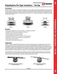
Figure 1.<br />
Sectionalizing Switches. Three-phase Bolt-In (left) and three-phase Quick-Mount<br />
(right).<br />
PRODUCTION TESTS<br />
Tests are conducted in accordance with<br />
Cooper Power Systems requirements:<br />
■ Physical Inspection<br />
■ Mechanical operations<br />
■ Operating torque<br />
■ Contact pressure<br />
■ Switch contact resistance<br />
INSTALLATION<br />
The switch is either horizontally or<br />
vertically mounted, depending on the<br />
application and the selected switch type.<br />
The vertically mounted switch is typically<br />
used in transformers/switchgear<br />
installed below grade, where the switch<br />
would be mounted in the cover of that<br />
particular equipment. All exposed parts<br />
of the vertically mounted switch are<br />
made from stainless steel or other noncorrosive<br />
materials. Both types of<br />
switches, including the mechanism,<br />
must be completely immersed under<br />
the insulating fluid.<br />
NOTE: For all mounting systems,<br />
refer to S800-64-2 for more<br />
detailed installation<br />
instructions.<br />
1
Four-Position Sectionalizing Loadbreak Switches<br />
Figure 2.<br />
Switch features and description.<br />
* DuPont Zytel ® HTN (High Temperature Nylon)<br />
Figure 3.<br />
Make-Before-Break switch features and description (See Table 5 for application details).<br />
2<br />
ARC BARRIER<br />
Prevents stretched arcs<br />
from jumping across phases<br />
or phase-to-ground<br />
(earth) during switching.<br />
(One barrier<br />
removed for<br />
illustrative purposes)<br />
ARC SUPPRESSOR PADDLE<br />
FIBERGLASS SHAFT<br />
A fiberglass wound shaft with a<br />
solid pultruded core provides a high<br />
strength non-twisting connection<br />
between blades and the switch<br />
mechanism.<br />
ARC SUPPRESSOR PADDLE<br />
The arc suppressor paddle forces<br />
insulating fluid across the contacts to<br />
assist in stretching and extinguishing<br />
the arc during switching.<br />
ARC BARRIER<br />
SILVER PLATED COPPER CONTACTS<br />
Provides a low resistance connection<br />
with the moving blades.<br />
SWITCH MECHAMISM<br />
A spring-loaded activating mechanism ensures<br />
quick loadbreak action and positive contact<br />
engagement through all positions.<br />
SILVER PLATED<br />
COPPER CONTACTS<br />
SILVER PLATED COPPER BLADE<br />
The moving blades are available in four different<br />
configurations or switch types; Straight, Selector,<br />
V-blade or T-blade. In addition the V-blade and<br />
the T-blade have a Make-Before-Break option.<br />
MOUNTING PLATE (QUICK-MOUNT* SHOWN)<br />
Two mounting options are available; Bolt-In<br />
System and Quick-Mount System. The Bolt-In<br />
System requires four (4) couplings to be welded<br />
to the inside of the tank. Refer to Figure 6 for<br />
coupling placement and dimensional<br />
information. The Quick-Mount System provides<br />
a fast and easy installation without additional<br />
bolts and welded couplings.<br />
LIMIT PLATE<br />
The limit plate can be used to assure<br />
only one operation is performed each<br />
time the switch is operated.<br />
HANDLE<br />
All horizontally mounted switches<br />
are furnished with cast aluminum<br />
handles. Vertically mounted switches<br />
are typically used in transformers or<br />
switchgear mounted below grade and<br />
the switches are therefore furnished<br />
with brass handles and non-corrosive<br />
external parts.<br />
SILVER PLATED COPPER BLADE (MBB<br />
T-BLADE SHOWN)<br />
The MBB blade eliminates the momentary<br />
interruption during switching associated<br />
with connection type load-breaking<br />
switches. The MBB option also eliminates<br />
the need for multiple “on/off” switches<br />
required to avoid momentary switching<br />
interruptions.
ELECTRICAL RATINGS<br />
TABLE 1<br />
Ratings and Characteristics per IEEE C37.71 – 2001 <br />
Units<br />
12.5 kA Rated Switches<br />
To IEEE C37.71 - 2001 Rated Voltage<br />
Maximum rating phase-to-phase kV 15.5 27.8 38<br />
Maximum rating phase-to-ground kV 9 17.2 21.9<br />
Power Frequency Hz 60 60 60<br />
Current rating (Continuous)<br />
Loadbreak Capability @ 0.75<br />
A 630 300 200<br />
Power Factor A 630 300 200<br />
First peak min. kV 4 7.6 13<br />
Time-to-peak max. µs 180 290 424<br />
Magnetizing A 22 10.5 7<br />
Cable Charging<br />
Fault Withstand Current (Momentary)<br />
A 10 25 40<br />
10 cycle symmetric rms kA 12.5 12.5 12.5<br />
10 cycle asymmetric rms kA 18.6 18.6 18.6<br />
10 cycle peak<br />
Fault Withstand (Short-time)<br />
kA 32.5 32.5 32.5<br />
1s rms kA 12.5 12.5 12.5<br />
2s rms<br />
Fault Close and Latch<br />
kA 12.5 12.5 12.5<br />
10 cycle symmetric rms kA 12.5 12.5 12.5<br />
10 cycle asymmetric rms kA 18.6 18.6 18.6<br />
10 cycle peak<br />
Impulse Withstand Voltage (1.2/50µs)<br />
kA 32.5 32.5 32.5<br />
To ground and between phases kV 95 125 150<br />
Across open contacts<br />
Power Frequency (1 minute)<br />
kV 95 125 150<br />
To ground and between phases kV 35 60 70<br />
Across open contacts<br />
DC Withstand (15 minutes)<br />
kV 35 60 70<br />
To ground and between phases kV 53 78 103<br />
Across open contacts kV 53 78 103<br />
Corona (Extinction) kV 26 26 26<br />
Temperature Maximum at 630 A<br />
Temp. Rise Above Ambient Air at<br />
°C 75 75 75<br />
630 A (Max.) °K 35 35 35<br />
Mechanical Life (Minimum Operations): 5,000 5,000 5,000<br />
TABLE 2<br />
Ratings and Characteristics per IEC 60265-1 – 1998<br />
800-64<br />
Units<br />
16 kA Rated Switches<br />
To IEC 60265-1 - 1998<br />
Switch Rating<br />
Rated Voltage<br />
kV 15 24 36<br />
Maximum rating phase-to-phase kV 15.5 24.9 38<br />
Maximum rating phase-to-earth kV 9 14.4 21.9<br />
Power Frequency Hz 50/60 50/60 50/60<br />
No-Load Transformer Breaking Current A 6.3 4 2<br />
Current Rating (Continuous) A 630 400 200<br />
Mainly Active Load Breaking Current A 630 400 200<br />
First peak min. kV 25.7 41 65.1<br />
Time-to-peak max. µs 72 88 108<br />
Closed Loop Breaking Current A 630 400 200<br />
Line Charging Current A 1 1.5 2<br />
Cable Charging Current A 10 17 25<br />
Earth Fault Switching Current A 1 10 8<br />
Cable and Line Charging Under Earth Fault<br />
Short-time Withstand Current<br />
A 17.5 17 26<br />
1s rms kA 18 18 18<br />
2s rms kA 16 16 16<br />
3s rms<br />
Short-circuit Making Current<br />
kA 13 13 13<br />
12 cycle symmetric rms (min.) kA 16 16 16<br />
12 cycle asymmetric rms (min.) kA 24.8 24.8 24.8<br />
12 cycle max. peak (min.)<br />
Impulse Withstand Voltage (1.2/50µs)<br />
kA 41.6 41.6 41.6<br />
To earth and between phases<br />
Across open contacts<br />
kV 170 170 170<br />
(isolating distance)<br />
Power Frequency (1 Minute)<br />
kV 195 195 195<br />
To earth and between phases<br />
Across open contacts<br />
kV 70 70 70<br />
(isolating distance) kV 80 80 80<br />
Corona (Extinction) kV 26 26 26<br />
Temperature Maximum at 630 A<br />
Temp. Rise Above Ambient Air at<br />
°C 90 90 90<br />
630 A (Max.) °K 50 50 50<br />
Mechanical Life (Minimum Operations): 5,000 5,000 5,000<br />
3
Four-Position Sectionalizing Loadbreak Switches<br />
DIMENSIONAL INFORMATION<br />
Figure 4.<br />
Line illustration with dimensions of sectionalizing switch with “Quick-Mount System.”<br />
Notes:<br />
1. Dimensions given in Figure 4 and Table 3 are for reference only.<br />
2. Handle can be used on 14 gauge .075 inch (1.9 mm) to .25 inch (6.4 mm) thick frontplate. 14 gauge shown.<br />
3. Optional padlock handle is available. (See Table 7, Figure 7.)<br />
TABLE 3<br />
Dimensional Information for Figure 4 (Inches/mm)<br />
4<br />
.89<br />
(23 mm)<br />
C B<br />
D<br />
A<br />
F<br />
NUT & LOCKING NUT RETAINER<br />
FURNISHED WITH SWITCH<br />
ARC<br />
BARRIER<br />
A D E F<br />
No. of<br />
Decks/<br />
Phases<br />
kV Rating &<br />
Blade Type<br />
Horizontal Mount<br />
B C<br />
Horizontal Mount<br />
1<br />
All 8.14"<br />
207 mm<br />
– – 7.25"<br />
184 mm<br />
0.75"<br />
19 mm<br />
8.54"<br />
217 mm<br />
2<br />
All 12.23"<br />
311 mm<br />
4.09"<br />
104 mm<br />
– 7.25"<br />
184 mm<br />
0.75"<br />
19 mm<br />
12.54"<br />
319 mm<br />
3<br />
12 kA T Blade<br />
12 & 16 kA 16.3" 4.09" 4.09" 7.25" 0.75" 16.54"<br />
Selector,<br />
Straight, &<br />
V Blade<br />
414 mm 104 mm 104 mm 184 mm 19 mm 420 mm<br />
3 16 kA 16.7"" 4.09" 4.09" 7.65"" 0.75" 16.94"<br />
T Blade Only 424 mm 104 mm 104 mm 194 mm 19 mm 430 mm<br />
E<br />
TANK WALL<br />
5.15"<br />
(131 mm)<br />
TYP<br />
SEE<br />
NOTES<br />
2 and 3<br />
Ø .39" HOLE<br />
(10 mm)<br />
ALL LINE<br />
CONNECTIONS<br />
7.51"<br />
(191 mm)<br />
4.38"<br />
(111 mm)<br />
5.40"<br />
(137 mm)<br />
8.32"<br />
(211 mm)<br />
R<br />
2.75"<br />
(70 mm)
Figure 5.<br />
Line illustration with dimensions of sectionalizing switch with “Bolt-In System.”<br />
Notes: 1. Dimensions given in Figure 5 and Table 4 are for reference only.<br />
2. Handle can be used on 14 gauge .075 inch (1.9 mm) to .25 inch (6.4 mm) thick frontplate. 14 gauge shown.<br />
3. Optional padlock handle is available. (See Table 7, Figure 7.)<br />
1.320" MIN.<br />
(33.5 mm)<br />
DIAMETER<br />
HOLE<br />
2.750"<br />
(70 mm)<br />
.140"<br />
(4 mm)<br />
RADIUS<br />
2.187"<br />
(56 mm)<br />
TYPICAL<br />
ON INSIDE WALL:<br />
COUPLING WITH .394" (10 mm)<br />
INTERNAL TAPPED THREAD<br />
x .79" (20 mm) LONG<br />
C<br />
.89<br />
(23 mm)<br />
TABLE 4<br />
Dimensional Information for Figure 5 (inches/mm)<br />
4.375"<br />
(111 mm)<br />
1.5"<br />
(38.1 mm)<br />
TYPICAL<br />
Figure 6a.<br />
Hole, coupling and weld pin placement (Bolt-In system).<br />
B<br />
F<br />
TANK SEALING<br />
GLAND FURNISHED<br />
WITH SWITCH<br />
1.375"<br />
(35 mm)<br />
TYPICAL<br />
.662"<br />
(17 mm)<br />
1.5"<br />
(38.1 mm)<br />
TYPICAL<br />
ON OUTSIDE WALL:<br />
.312" DIAMETER x .630" LONG<br />
(8 mm) (16 mm)<br />
WELD PIN<br />
Notes:<br />
Couplings & Weld pins not included with switch. Pre-Welded conversion mounting<br />
brackets available. (See Table 7)<br />
All couplings and pins to be welded flat within an angularity tolerance of ± one half<br />
degree.<br />
A<br />
D<br />
E<br />
Ø .44" (11 mm)<br />
MTG. HOLES<br />
TANK WALL<br />
5.15"<br />
(131 mm)<br />
TYP<br />
SEE<br />
NOTES<br />
2 and 3<br />
ARC<br />
BARRIER<br />
Ø .39" HOLE<br />
(10 mm)<br />
ALL LINE CONNECTIONS<br />
8.32" (211 mm)<br />
8.35"<br />
(212 mm)<br />
4.38"<br />
(111 mm)<br />
5.40"<br />
(137 mm)<br />
2.75"<br />
(70 mm)<br />
Figure 6b.<br />
Hole and weld pin placement (Quick-Mount system).<br />
800-64<br />
No. of<br />
Decks/ kV Ratings<br />
A<br />
Horizontal Vertical B C<br />
D<br />
Horizontal Vertical<br />
E<br />
Horizontal Vertical<br />
F<br />
Horizontal Vertical<br />
Phases & Blade Type Mount Mount Mount Mount Mount Mount Mount Mount<br />
1<br />
All 8.05"<br />
204 mm<br />
13.3"<br />
338 mm<br />
– – 7.16"<br />
182 mm<br />
12.4"<br />
315 mm<br />
0.75"<br />
19 mm<br />
6.00"<br />
152 mm<br />
8.46"<br />
215 mm<br />
13.7"<br />
348 mm<br />
2<br />
All 12.1"<br />
307 mm<br />
17.4"<br />
442 mm<br />
4.09"<br />
104<br />
– 7.16"<br />
182 mm<br />
12.4"<br />
315 mm<br />
0.75"<br />
19 mm<br />
6.00"<br />
152 mm<br />
12.5"<br />
318 mm<br />
17.7"<br />
450 mm<br />
3<br />
12 kA T Blade<br />
12 & 16 kA 16.2" 21.5" 4.09" 4.09" 7.16" 12.4" 0.75" 6.00" 16.5" 21.7"<br />
Selector,<br />
Straight, &<br />
V Blade<br />
411 mm 546 mm 104 mm 104 mm 182 mm 315 mm 19 mm 152 mm 419 mm 551 mm<br />
3 16 kA 16.7" – 4.09" 4.09" 7.56" – 0.75" – 16.9" –<br />
T Blade Only 424 mm 104 mm 104 mm 192 mm 19 mm 429 mm<br />
DIAMETER 2.00"<br />
(51 mm)*<br />
1.320" MIN.<br />
(33.5 mm)<br />
DIA. HOLE<br />
3.00"<br />
(76 mm)<br />
TYPICAL<br />
1.50"<br />
(38 mm)<br />
TYPICAL<br />
3.00"<br />
(76 mm)<br />
TYPICAL<br />
1.50"<br />
(38 mm)<br />
TYPICAL<br />
.662"<br />
(17 mm)<br />
ON EXTERIOR WALL:<br />
DIAMETER<br />
6.25" Ø .312" DIAMETER<br />
X<br />
625" LONG<br />
(159 mm) (8 mm) (16 mm)<br />
(4) WELD PINS<br />
RADIUS.140"<br />
(4 mm)**<br />
* Exterior mounting surface must be flat within .010" (0.25 mm) over entire area.<br />
** Interior mounting surface must be clear of obstructions.<br />
5
Four-Position Sectionalizing Loadbreak Switches<br />
TABLE 5<br />
Wiring Schematics<br />
6<br />
SWITCH<br />
TYPE<br />
STRAIGHT BLADE<br />
SELECTOR BLADE<br />
ON-OFF<br />
SELECTOR BLADE<br />
1 BLADE SIDE<br />
TYPICAL DECAL<br />
STENCIL LAYOUT<br />
CLOSE<br />
OPEN OPEN<br />
CLOSE<br />
CLOSE<br />
OPEN OPEN<br />
OPEN<br />
LINE A TO C<br />
OPEN LINE B TO C<br />
OPEN<br />
SELECTOR BLADE<br />
1 BLADE CENTER<br />
LINE A TO C<br />
OPEN OPEN<br />
LINE B TO C<br />
V-BLADE<br />
BREAK BEFORE MAKE<br />
LINES A & B TO C A<br />
LINE A ONLY LINE B ONLY<br />
TO C TO C<br />
OPEN (ALL)<br />
V-BLADE<br />
MAKE BEFORE BREAK<br />
LINES A & B TO C A<br />
LINE A ONLY LINE B ONLY<br />
TO C TO C<br />
OPEN (ALL)<br />
T-BLADE<br />
BREAK BEFORE MAKE<br />
LINES A & B TO C<br />
VIEW OF<br />
CONTACTS FROM<br />
FRONT (HANDLE)<br />
END OF SWITCH<br />
A<br />
A<br />
A<br />
A<br />
A<br />
B<br />
C (COIL)<br />
C (COIL)<br />
C (COIL)<br />
C (COIL)<br />
B<br />
B<br />
C (COIL)<br />
B<br />
C (COIL)<br />
C (COIL)<br />
POSITION 1<br />
FRONT SCHEMATIC<br />
AS SHIPPED AND AS<br />
SHOWN AT LEFT<br />
A<br />
A<br />
CLOSE<br />
CLOSE<br />
OPEN<br />
C A<br />
C<br />
C<br />
POSITION 2<br />
POSITION 3<br />
POSITION 4<br />
SCHEMATIC SCHEMATIC<br />
SCHEMATIC<br />
SWITCH HANDLE SWITCH HANDLE SWITCH HANDLE<br />
ROTATED ROTATED ROTATED<br />
90° CLOCKWISE 90° CLOCKWISE<br />
90° CLOCKWISE<br />
FROM POSITION 1 FROM POSITION 2 FROM POSITION 3<br />
A<br />
A<br />
OPEN OPEN OPEN<br />
C A<br />
C A<br />
A-C B-C OPEN OPEN<br />
A B C A B C A B C A B C<br />
A-C OPEN B-C OPEN<br />
A C B A C B A C B A C B<br />
AB-C B-C OPEN A-C<br />
A B C A B C A B C A B C<br />
C<br />
A<br />
OPEN<br />
AB-C B-C OPEN A-C<br />
A B C A B C A B C A B C<br />
LINE A ONLY LINE B ONLY<br />
TO C TO C<br />
LINES A TO B<br />
C OPEN<br />
B<br />
AB-C B-C A-B A-C<br />
T-BLADE<br />
MAKE BEFORE BREAK<br />
A C B A C B A C B A C B<br />
LINES A & B TO C<br />
LINE A ONLY LINE B ONLY<br />
TO C TO C<br />
LINES A TO B<br />
C OPEN<br />
A C (COIL)<br />
B<br />
AB-C B-C A-B A-C<br />
A C B A C B A C B A C B<br />
NOTE:<br />
1. SWITCH CENTER IS PIVOT POINT. BLACK SEGMENTS OF BLADE ROTATE.<br />
WHITE OUTLINED SEGMENTS ARE STATIONARY.<br />
2. OTHER POSITION SEQUENCES AVAILABLE – CONSULT FACTORY FOR DETAILS.<br />
CLOSE<br />
C<br />
C
ORDERING<br />
INFORMATION<br />
To order a Cooper Power Systems<br />
four position sectionalizing loadbreak<br />
switch, specify the switch type<br />
desired from Table 5 and then build<br />
the catalog number from Table 6.<br />
TABLE 6<br />
Catalog Number Selection Chart<br />
1 2 3 4 5 6 7 8 9 10<br />
L S 4 B H 3 T 1 2 B<br />
CODE PRODUCT<br />
L LOADBREAK<br />
S SWITCH<br />
4 4-POSITION<br />
CODE INSTALLATION<br />
B BOLT-IN SYSTEM<br />
Q QUICK-MOUNT SYSTEM<br />
CODE ORIENTATION<br />
H HORIZONTAL<br />
V VERTICAL<br />
CODE NUMBER OF PHASES<br />
1 ONE<br />
2 TWO<br />
3 THREE<br />
TABLE 7<br />
Accessory Parts<br />
Description<br />
Conversion Mounting Bracket* for<br />
Catalog Number Drawing<br />
Bolt-In system.<br />
Includes hole, pins and couplings per Figure 6<br />
Conversion Mounting Bracket* for<br />
2037424C02M 4200738N<br />
Quick-Mount system.<br />
Includes hole and pins per Figure 6<br />
Padlockable Handle** per Figure 7<br />
2037424C04M 4200738N<br />
Aluminum 2239000B14 4201093N<br />
Brass 2239000B15 4201093N<br />
* Bracket is mild steel, 6" x 6" x 0.134" (152 mm x 152 mm x 3.4 mm).<br />
**Padlockable handle must be ordered separately.<br />
.40"<br />
(10.2 mm)<br />
.63"<br />
(15.9 mm)<br />
2.00"<br />
(50.8 mm)<br />
1.50"<br />
(38.1 mm)<br />
Figure 7.<br />
Padlockable Handle.<br />
1.75"<br />
(44.5 mm)<br />
2.38"<br />
(60.3 mm)<br />
Note: For use with interlock systems. Will not function<br />
with optional limit plate and weld pins.<br />
CODE CONTACT RATING<br />
12 12.5 kA (Table 1)<br />
16 16 kA (Table 2)<br />
800-64<br />
CODE ENGAGEMENT<br />
B BREAK BEFORE MAKE<br />
M MAKE BEFORE BREAK 1<br />
1 V- and T-blade only<br />
CODE SWITCH TYPE (See Table 5)<br />
V V - BLADE<br />
T T - BLADE<br />
S STRAIGHT BLADE<br />
D SELECTOR BLADE - (SIDE)<br />
R SELECTOR BLADE - (CENTER)<br />
L SELECTOR BLADE - (ON-OFF)<br />
ADDITIONAL<br />
INFORMATION<br />
Refer to the following reference literature<br />
for application recommendations:<br />
■ Service Section:<br />
Installation Instructions –<br />
S800-64-2<br />
■ Certified Test Report:<br />
12 kA Four Position<br />
Sectionalizing Loadbreak<br />
Switch – CP0316<br />
■ Certified Test Report:<br />
16kA Four Position<br />
Sectionalizing Loadbreak<br />
Switch – CP0313<br />
7
© 2003 Cooper Industries, Inc.<br />
R-Temp ® and Envirotemp ® are registered trademarks of Cooper Industries, Inc.<br />
FR3 is a trademark of Cooper Industries, Inc.<br />
IEEE ® is a registered trademark of the Institute of Electrical and Electronics<br />
Engineers, Inc.<br />
IEEE Standard C37.71-2001 is a trademark of the Institute of Electrical and<br />
Electronics Engineers, Inc.<br />
Zytel ® is a registered trademark of E. I. du Pont de Nemours and Company<br />
1045 Hickory Street<br />
Pewaukee, WI 53072 USA<br />
www.cooperpower.com<br />
MI<br />
12/03