RISH Ducer M01 with RS 485 interface ... - PROMELSA
RISH Ducer M01 with RS 485 interface ... - PROMELSA
RISH Ducer M01 with RS 485 interface ... - PROMELSA

Create successful ePaper yourself
Turn your PDF publications into a flip-book with our unique Google optimized e-Paper software.
<strong>RISH</strong> <strong>Ducer</strong> <strong>M01</strong> <strong>with</strong> <strong>RS</strong> <strong>485</strong> <strong>interface</strong><br />
Programmable multi-transducer<br />
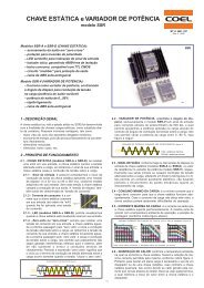
Fig. 1. The basic version universal<br />
<strong>RISH</strong> <strong>Ducer</strong> MXX in housing clipped onto a top-hat rail. T24,<br />
Application<br />
for the measurement of electrical variables in heavy<br />
current power systems<br />
<strong>RISH</strong> <strong>Ducer</strong> <strong>M01</strong> (Fig. 1) is a programmable transducer <strong>with</strong> <strong>RS</strong><br />
®<br />
<strong>485</strong> bus <strong>interface</strong> (MODBUS). It supervises several parameter of<br />
an electrical power system simultaneously.<br />
The <strong>RS</strong> <strong>485</strong> <strong>interface</strong> enables the user to determine the number varia-<br />
bles to be supervised (up to the maximum available). The levels of all<br />
internal counters that have been configured (max. 4) can also viewed.<br />
Provision is made for programming the <strong>RISH</strong> <strong>Ducer</strong> <strong>M01</strong> via the bus. A<br />
standard EIA <strong>485</strong> <strong>interface</strong> can be used.<br />
The transducers are also equipped <strong>with</strong> an <strong>RS</strong> 232 serial <strong>interface</strong><br />
to which a PC <strong>with</strong> the corresponding software can be connected<br />
for programming or accessing and executing useful ancillary functions.<br />
This <strong>interface</strong> is needed for bus operation to configure the device<br />
address, the Baud rate and possibly increasing the message waiting<br />
®<br />
time (if the master is too slow) defined in the MODBUSprotocol.<br />
The usual methods of connection, the types of measured variables,<br />
their ratings and the type of internal energy/metering are the main<br />
parameters that can be programmed.<br />
The ancillary functions include a power system check and a facility for<br />
printing nameplates.<br />
The transducer fulfils all the essential requirements and regulations<br />
concerning electromagnetic compatibility (EMC) and safety (IEC 1010<br />
resp. EN 61 010). It was developed and is manufactured and tested in<br />
strict accordance <strong>with</strong> the quality assurance standard ISO 9001.<br />
Unique Features<br />
Simultaneous measurement of several variables of a<br />
heavy-current power system / full supervision of an<br />
asymmetrically loaded four-wire power system, rated<br />
current 1 to 6 A, rated voltage 57 to 400V (phasetoneutral)<br />
or 100 to 693V (phase-to-phase)<br />
Rishabh Instruments<br />
Measured variables Output<br />
Without analogue<br />
Types<br />
outputs, <strong>with</strong> bus<br />
Current, Voltage (rms),<br />
<strong>Ducer</strong> <strong>M01</strong><br />
<strong>interface</strong> <strong>RS</strong> <strong>485</strong><br />
active/reactive/apparent power (MODBUS)<br />
Cos�, sin�, power factor 4 analogue and<br />
RMS value of the current <strong>with</strong><br />
wire setting range (bimetal<br />
bus <strong>interface</strong><br />
<strong>RS</strong> <strong>485</strong><br />
<strong>Ducer</strong> M40<br />
measuring function)<br />
(MODBUS)<br />
Slave pointer function for the 2 analogue and<br />
measurement of the RMS<br />
value IB<br />
Frequency<br />
Average value of the currents<br />
<strong>with</strong> sign of the active power<br />
(power symbol only)<br />
4 digital outputs<br />
or<br />
4 analogue and<br />
2 digital outputs<br />
see Data sheet<br />
Data bus LON<br />
see Data Sheet<br />
M00<br />
<strong>Ducer</strong> M24<br />
<strong>Ducer</strong> M42<br />
<strong>Ducer</strong> M00<br />
For all heavy-current power system variables<br />
Input voltage up to 693 V (phase-to-phase)<br />
Universal analogue outputs (programmable)<br />
®<br />
Transfer of data via MODBUS <strong>interface</strong><br />
High accuracy: U/I 0.2%, (under reference conditions)<br />
Universal digital outputs (meter transmitter, limits)<br />
4 integrated energy meters, storage every each 203 s,<br />
storage for : 20 years<br />
Windows software <strong>with</strong> password protection for<br />
programming, data analysis, power system status<br />
simulation, acquisition of meter data and making settings<br />
DC-, AC- power pack <strong>with</strong> wide power supply tolerance /<br />
universal<br />
Provision for either snapping the transducer onto top - hat<br />
rails or securing it <strong>with</strong> screws to a wall or panel<br />
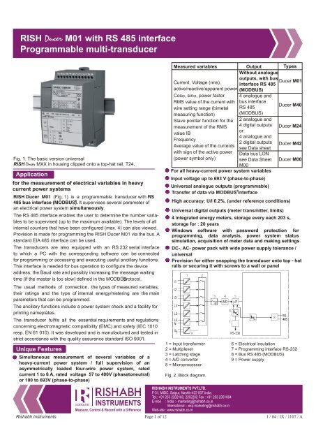
1 = Input transformer<br />
2 = Multiplexer<br />
3 = Latching stage<br />
4 = A/D converter<br />
5 = Microprocessor<br />
<strong>RISH</strong>ABH INSTRUMENTS PVT.LTD.<br />
F-31, MIDC, Satpur, Nashik-422 007,India.<br />
Tel.: +91 253 2202160, 2202202 Fax : +91 253 2351064<br />
E-mail : India :- marketing@rishabh.co.in<br />
International :- exp.marketing@rishabh.co.in<br />
Web-site : www.rishabh.co.in<br />
Page 1 of 12<br />
Fig. 2. Block diagram.<br />
6 = Electrical insulation<br />
7 = Programming <strong>interface</strong> <strong>RS</strong>-232<br />
8 = Bus <strong>RS</strong> <strong>485</strong> (MODBUS)<br />
9 = Power supply<br />
1 / 04 / IX / 1107 / A
<strong>RISH</strong> <strong>Ducer</strong> <strong>M01</strong> <strong>with</strong> <strong>RS</strong> <strong>485</strong> <strong>interface</strong><br />
Programmable multi-transducer<br />
Symbols and their meaning<br />
Symbols Meaning<br />
X Measured variable<br />
X0 Lower limit of the measured variable<br />
X1 Break point of the measured variable<br />
X2 Upper limit of the measured variable<br />
Y Output variable<br />
Y0 Lower limit of the output variable<br />
Y1 Break point of the output variable<br />
Y2 Upper limit of the output variable<br />
U Input voltage<br />
Ur Rated value of the input voltage<br />
U 12 Phase-to-phase voltage L1 - L2<br />
U 23 Phase-to-phase voltage L2 - L3<br />
U 31 Phase-to-phase voltage L3 - L1<br />
U1N Phase-to-neutral voltage L1 - N<br />
U2N Phase-to-neutral voltage L2 - N<br />
U3N Phase-to-neutral voltage L3 - N<br />
UM Average value of the voltages<br />
Rishabh Instruments<br />
(U1N + U2N + U3N) / 3<br />
I Input current<br />
I1 AC current L1<br />
I2 AC current L2<br />
I3 AC current L3<br />
Ir Rated value of the input current<br />
IM Average value of the currents (I1+ I2 + I3) / 3<br />
IMS Average value of the currents and sign of the active<br />
power (P)<br />
IB RMS value of the current <strong>with</strong> wire setting range<br />
(bimetal measuring function)<br />
IBT Response time for IB<br />
BS Slave pointer function for the measurement of the<br />
RMS value IB<br />
BST Response time for BS<br />
� Phase-shift between current and voltage<br />
F Frequency of the input variable<br />
Fn Rated frequency<br />
P Active power of the system P=P1+P2 + P3<br />
P1 Active power phase 1 (phase-to-neutral L1 - N)<br />
P2 Active power phase 2 (phase-to-neutral L2 - N)<br />
P3 Active power phase 3 (phase-to-neutral L3 - N)<br />
Symbols Meaning<br />
Q Reactive power of the system Q = Q1+ Q2 + Q3<br />
Q1 Reactive power phase 1 (phase-to-neutral L1-N)<br />
Q2 Reactive power phase 2 (phase-to-neutral L2-N)<br />
Q3 Reactive power phase 3 (phase-to-neutral L3-N)<br />
S Apparent power of the system<br />
S1 Apparent power phase 1<br />
(phase-to-neutral L1-N)<br />
S2 Apparent power phase 2<br />
(phase-to-neutral L2-N)<br />
S3 Apparent power phase 3<br />
(phase-to-neutral L3-N)<br />
Sr Rated value of the apparent power of the system<br />
PF Active power factor cos � =P/S<br />
PF1 Active power factor phase1 P1/S1<br />
PF2 Active power factor phase2 P2/S2<br />
PF3 Active power factor phase3 P3/S3<br />
QF Reactive power factor sin j =Q/S<br />
QF1 Reactive power factor phase1 Q1/S1<br />
QF2 Reactive power factor phase2 Q2/S2<br />
QF3 Reactive power factor phase3 Q3/S3<br />
LF Power factor of the system<br />
LF = sgnQ (1- PF )<br />
LF1 Power factor phase 1<br />
sgnQ1 (1 - PF1 )<br />
LF2 Power factor phase 2<br />
sgnQ2 (1 - PF2 )<br />
LF3 Power factor phase 3<br />
sgnQ3 (1 - PF3 )<br />
H Power supply<br />
Hn Rated value of the power supply<br />
CT c.t. ratio<br />
VT v.t. ratio<br />
� �<br />
S = I + I + I U + U + U<br />
2 2 2 2 2 2<br />
1 2 3 1 2 3<br />
<strong>RISH</strong>ABH INSTRUMENTS PVT.LTD.<br />
F-31, MIDC, Satpur, Nashik-422 007,India.<br />
Tel.: +91 253 2202160, 2202202 Fax : +91 253 2351064<br />
E-mail : India :- marketing@rishabh.co.in<br />
International :- exp.marketing@rishabh.co.in<br />
Web-site : www.rishabh.co.in<br />
Page 2 of 12<br />
1 / 04 / IX / 1107 / A
<strong>RISH</strong> <strong>Ducer</strong> <strong>M01</strong> <strong>with</strong> <strong>RS</strong> <strong>485</strong> <strong>interface</strong><br />
Programmable multi-transducer<br />
Applicable standards and regulations<br />
IEC 688 or<br />
DIN EN 60 688 Electrical measuring transducers for<br />
converting AC electrical variables into<br />
analogue and digital signals<br />
IEC 1010 or<br />
EN 61 010 Safety regulations for electrical measuring,<br />
control and laboratory equipment<br />
IEC 529 or<br />
EN 60 529 Protection types by case (code IP)<br />
IEC 255-4 Part E5 High-frequency disturbance test<br />
(static relays only)<br />
IEC 1000-4-2/-3/-4/-6 Electromagnetic compatibility for industrialprocess<br />
measurement and control<br />
equipment<br />
EN 55 011 Electromagnetic compatibility of data<br />
processing and telecommunication<br />
equipment Limits and measuring principles<br />
for radio interference and information<br />
equipment<br />
IEC 68-2-1/-2/-3/-6/-27<br />
or<br />
EN 60 068-2-1/-2/-3/-6/-27 Ambient tests<br />
-1 Cold, -2 Dry heat,<br />
-3 Damp heat, -6 Vibration,<br />
-27 Shock<br />
DIN 40 110 AC quantities<br />
DIN 43 807 Terminal markings<br />
IEC 1036 Alternating current static watt-hour meters<br />
for active energy (classes 1and 2)<br />
DIN 43 864 Current <strong>interface</strong> for the transmission of<br />
impulses between impulse encoder counter<br />
and tarif meter<br />
UL 94 Tests for flammability of plastic materials for<br />
parts in devices and appliances<br />
parts in devices and appliances<br />
Technical data<br />
Input<br />
Input variables: : see Table 3 and 4<br />
Measuring ranges: : see Table 3 and 4<br />
Waveform: : Sinusoidal<br />
Rated frequency : 50...60 Hz; 16 2/3 Hz<br />
Own consumption [VA]<br />
Rishabh Instruments<br />
:<br />
2<br />
Voltage circuit: � U / 400 k�<br />
Condition:<br />
Characteristic XH 01...XH10<br />
Current circuit: � I2 0.01 �<br />
Continuous thermal ratings of inputs<br />
Current circuit<br />
<strong>RISH</strong>ABH INSTRUMENTS PVT.LTD.<br />
F-31, MIDC, Satpur, Nashik-422 007,India.<br />
Tel.: +91 253 2202160, 2202202 Fax : +91 253 2351064<br />
E-mail : India :- marketing@rishabh.co.in<br />
International :- exp.marketing@rishabh.co.in<br />
Web-site : www.rishabh.co.in<br />
Page 3 of 12<br />
10A 400 V<br />
single-phase<br />
AC system<br />
693 V<br />
three-phase system<br />
Voltage circuit 480V single-phase AC system<br />
831V three-phase system<br />
Short-time thermal rating of inputs<br />
Input<br />
variable<br />
Number of<br />
inputs<br />
Duration<br />
of<br />
overload<br />
Current circuit 400 V single-phase AC system<br />
693 V three-phase system<br />
100 A 5 3 s 5 min.<br />
250 A 1 1 s 1 hour<br />
Voltage circuit 1 A, 2 A, 5 A<br />
Intervall<br />
between two<br />
overloads<br />
Single-phase<br />
AC system<br />
600 V<br />
H intern: 1.5 Ur 10 10 s 10 min.<br />
Three-phase<br />
system<br />
1040 V<br />
H intern: 1.5 Ur 10 10 s 10 s<br />
®<br />
MODBUS (Bus <strong>interface</strong> <strong>RS</strong>-<strong>485</strong>)<br />
Terminals : Screw terminals, terminals<br />
23, 24, 25 and 26<br />
Connecting cable : Screened twisted pair<br />
Max. distance : Approx. 1200 m (approx. 4000 ft.)<br />
Baudrate : 1200 … 9600 Bd (programmable)<br />
Number of bus<br />
stations<br />
:<br />
32 (including master)<br />
Dummy load : Not required<br />
®<br />
MODBUS is a registered trademark of the Schneider Automation Inc.<br />
1 / 04 / IX / 1107 / A
<strong>RISH</strong> <strong>Ducer</strong> <strong>M01</strong> <strong>with</strong> <strong>RS</strong> <strong>485</strong> <strong>interface</strong><br />
Programmable multi-transducer<br />
Reference conditions<br />
Ambient temperature :<br />
o<br />
15...30 C<br />
Pre-conditioning : 30 min. acc. to DIN EN 60 688<br />
Input variable : Rated useful range<br />
Power supply : H =Hn + 1%<br />
Active/reactive factor : cos��=1 resp. sin �� = 1<br />
Frequency : 50 ... 60 Hz, 16 2/3 Hz<br />
Waveform : Sinusoidal, form factor 1.1107<br />
Output load : DC current output:<br />
Miscellaneous : EN 60 688<br />
System response<br />
Accuracy class<br />
Duration of the<br />
: 0.2 resp. 0.4 at applications <strong>with</strong><br />
phase-shift<br />
measurement cycle : Approx. 0.5 to 1.2 s at 50 Hz,<br />
depending on measured variable<br />
and programming<br />
Response time : 1 … 2 times the measurement cycle<br />
Influencing quantities and permissible variations<br />
Acc. to EN 60 688<br />
Safety<br />
Protection class : II (protection isolated, EN 61 010-1)<br />
Enclosure protection: : IP 40, housing<br />
IP 20, terminals<br />
Overvoltage category: : III<br />
Insulation test<br />
(versus earth) : Input voltage: AC 400 V<br />
Input Current: AC 400 V<br />
<strong>RS</strong> <strong>485</strong>: DC 40 V<br />
Power supply: AC 400 V<br />
DC 230 V<br />
Surge test : 5 kV; 1.2/50 �s; 0.5 Ws<br />
Test voltages : 50 Hz, 1 min. according to<br />
EN 61 010-1<br />
5550 V, inputs versus all other circuits<br />
as well as outer surface<br />
Power Supply<br />
DC-, AC - power pack (DC and 50 ... 60 Hz)<br />
Table 1: Rated voltages and tolerances<br />
Rated voltage UN 24 ... 60 V DC/AC<br />
85 ... 230 V DC/AC<br />
Consumption : ��9 W resp. �10<br />
VA<br />
Rishabh Instruments<br />
3250 V, input circuits versus each<br />
other<br />
3700 V, power supply versus <strong>RS</strong> <strong>485</strong><br />
and SCI as well as outer surface<br />
490 V, <strong>RS</strong> <strong>485</strong> versus SCI as well as<br />
outer surface<br />
Tolerance<br />
DC -15 ... + 33%<br />
AC +10%<br />
Programming connector on transducer<br />
Interface: : <strong>RS</strong> 232 C<br />
DSUB socket: : 9-pin<br />
CTS<br />
RTS<br />
DSR<br />
GND<br />
DTR<br />
TXD<br />
RXD<br />
<strong>RISH</strong>ABH INSTRUMENTS PVT.LTD.<br />
F-31, MIDC, Satpur, Nashik-422 007,India.<br />
Tel.: +91 253 2202160, 2202202 Fax : +91 253 2351064<br />
E-mail : India :- marketing@rishabh.co.in<br />
International :- exp.marketing@rishabh.co.in<br />
Web-site : www.rishabh.co.in<br />
Page 4 of 12<br />
The <strong>interface</strong> is electrically insulated<br />
fromall other circuits<br />
Installation data<br />
Housing : Housing T24<br />
See Section "Dimensioned drawings”<br />
Housing material : Lexan 940 (polycarbonate),<br />
flammability class V-0 acc. to UL 94,<br />
self-extinguishing, non-dripping, free<br />
of halogen<br />
Mounting : For snapping onto top-hat rail<br />
(35X15 mm or 35X7.5 mm) acc. to<br />
EN 50 022<br />
or<br />
directly onto a wall or panel using<br />
the pull-out screw hole brackets<br />
Orientation : Any<br />
Weight : approx. 0.7 kg<br />
Terminals<br />
Type : Screw terminals <strong>with</strong> wire guards<br />
Max. wire gauge:<br />
Ambient tests<br />
EN 60 068-2-6 : Vibration<br />
Acceleration : + 2 g<br />
Ambient conditions<br />
Variations due to ambient<br />
temperature:<br />
Nominal range of use<br />
for temperature<br />
:<br />
:<br />
:<br />
2<br />
� 4.0 mm single wire or<br />
2<br />
2 X 2.5 mm fine wire<br />
frequency : 3 X 50 g<br />
3 shocks each in 6 directions<br />
Acceleration : Cold, dry heat, damp heat<br />
+ 0.1% / 10 K<br />
Storage temperature - 40 to + 85 C<br />
0<br />
:<br />
Annual mean<br />
relative humidity � 75%<br />
:<br />
0<br />
0... 15...30...45 C (usage group II)<br />
1 / 04 / IX / 1107 / A
<strong>RISH</strong> <strong>Ducer</strong> <strong>M01</strong> <strong>with</strong> <strong>RS</strong> <strong>485</strong> <strong>interface</strong><br />
Programmable multi-transducer<br />
Table 2: Rish<strong>Ducer</strong> MXX, standard version<br />
The versions of the transducer below programmed <strong>with</strong> the basic configuration are available ex stock. It is only necessary to quote the<br />
Description / Basic programming Marking<br />
1. Mechanical design: Housing T24 for rail and wall mounting<br />
2. Rated input frequency: 50 Hz<br />
3. Power supply: 24… 60 V DC, AC<br />
Rishabh Instruments<br />
85…230 V DC, AC<br />
4. Power supply connection: External connection (standard)<br />
5. Test certificate: None supplied<br />
6. Configuration: Programmed basic configuration<br />
See Table 4: “Ordering information”<br />
Basic configuration<br />
1. Application (system): 4-wire, 3-phase system, asymmetric load<br />
2. Input voltage: Design value Ur = 400 V<br />
3. Input current: Design value Ir = 5 A<br />
4. Primary rating: Without specification of primary rating<br />
5. Energy meter 1: Not used<br />
6. Energy meter 2: Not used<br />
7. Energy meter 3: Not used<br />
8. Energy meter 4: Not used<br />
See Table 3: “Programming”<br />
Table 3: Programming<br />
Description / Basic programming<br />
1. Application (system)<br />
Single-phase AC<br />
3-wire, 3-phase symmetric load, phase-shift U: L1-L2, I: L1 *<br />
3-wire, 3-phase symmetric load<br />
4-wire, 3-phase symmetric load<br />
3-wire, 3-phase symmetric load, phase-shift U: L3-L1, I: L1 *<br />
3-wire, 3-phase symmetric load, phase-shift U: L2-L3, I: L1 *<br />
3-wire, 3-phase asymmetric load<br />
4-wire, 3-phase asymmetric load<br />
4-wire, 3-phase asymmetric load, open-Y<br />
<strong>RISH</strong>ABH INSTRUMENTS PVT.LTD.<br />
F-31, MIDC, Satpur, Nashik-422 007,India.<br />
Tel.: +91 253 2202160, 2202202 Fax : +91 253 2351064<br />
E-mail : India :- marketing@rishabh.co.in<br />
International :- exp.marketing@rishabh.co.in<br />
Web-site : www.rishabh.co.in<br />
Page 5 of 12<br />
A11 … A16<br />
<strong>M01</strong> - 1<br />
1<br />
7<br />
8<br />
1<br />
0<br />
0<br />
A 44<br />
U 21<br />
V 2<br />
W 0<br />
EA 00<br />
FA 00<br />
GA 00<br />
HA 00<br />
Application<br />
Order No.<br />
A34 A24 / A44<br />
A11 ––– –––<br />
A12 ––– –––<br />
A13 ––– –––<br />
A14 ––– –––<br />
A15 ––– –––<br />
A16 ––– –––<br />
––– A34 –––<br />
––– ––– A44<br />
––– ––– A24<br />
1 / 04 / IX / 1107 / A
<strong>RISH</strong> <strong>Ducer</strong> <strong>M01</strong> <strong>with</strong> <strong>RS</strong> <strong>485</strong> <strong>interface</strong><br />
Programmable multi-transducer<br />
Table 3: Programming<br />
Description / Basic programming<br />
2. Rated input voltage<br />
Rated value Ur = 57.7 V<br />
Rated value Ur = 63.5 V<br />
Rated value Ur = 100 V<br />
Rated value Ur = 110 V<br />
Rated value Ur = 120 V<br />
Rated value Ur = 230 V<br />
Rated value Ur [V]<br />
Rated value Ur = 100 V<br />
Rated value Ur = 110 V<br />
Rated value Ur = 115 V<br />
Rated value Ur = 120 V<br />
Rated value Ur = 400 V<br />
Rated value Ur = 500 V<br />
Rated value Ur [V]<br />
Lines U01 to U06: Only for single phase AC current or<br />
4-wire, 3-phase symmetric load<br />
Line U91: Ur [V] 57 to 400<br />
Line U93: Ur [V] > 100 to 693<br />
3. Rated input current<br />
Rated value Ir = 1 A V1<br />
Rated value Ir = 2 A V2<br />
Rated value Ir = 5 A V3<br />
Rated value Ir > 1 to 6 [A]<br />
4. Primary rating (voltage and current transformer)<br />
Without specification of primary rating<br />
VT = kV CT = A<br />
Line W9: Specify transformer ratio primary, e.g. 33 kV, 1000 A<br />
The secondary ratings must correspond to the rated input<br />
voltage and current specified for feature 2, respectively 3.<br />
Rishabh Instruments<br />
A11 … A16<br />
<strong>RISH</strong>ABH INSTRUMENTS PVT.LTD.<br />
F-31, MIDC, Satpur, Nashik-422 007,India.<br />
Tel.: +91 253 2202160, 2202202 Fax : +91 253 2351064<br />
E-mail : India :- marketing@rishabh.co.in<br />
International :- exp.marketing@rishabh.co.in<br />
Web-site : www.rishabh.co.in<br />
Application<br />
A34 A24 / A44<br />
U01 ––– –––<br />
U02 ––– –––<br />
U03 ––– –––<br />
U04 ––– –––<br />
U05 ––– –––<br />
U06 ––– –––<br />
U91 ––– –––<br />
U21 U21 U21<br />
U22 U22 U22<br />
U23 U23 U23<br />
U24 U24 U24<br />
U25 U25 U25<br />
U26 U26 U26<br />
U93 U93 U93<br />
V1 V1<br />
V2 V2<br />
V3 V3<br />
V9 V9 V9<br />
W0 W0 W0<br />
W9 W9 W9<br />
5. Energy meter 1<br />
Not used EA00 EA00 EA00 I System [Ah]<br />
I1 L1 [Ah]<br />
I2 L2 [Ah]<br />
I3 L3 [Ah]<br />
S System [VAh]<br />
S1 L1 [VAh]<br />
S2 L2 [VAh]<br />
S3 L3 [VAh]<br />
P System (incoming) [Wh]<br />
P1 L1 (incoming) [Wh]<br />
P2 L2 (incoming) [Wh]<br />
P3 L3 (incoming) [Wh]<br />
Continuation “5. Energy Meter 1” see next page!<br />
Page 6 of 12<br />
EA50 ––– –––<br />
––– EA51 EA51<br />
––– EA52 EA52<br />
––– EA53 EA53<br />
EA54 EA54 EA54<br />
––– ––– EA55<br />
––– ––– EA56<br />
––– ––– EA57<br />
EA58 EA58 EA58<br />
––– ––– EA59<br />
––– ––– EA60<br />
––– ––– Ea61<br />
1 / 04 / IX / 1107 / A
<strong>RISH</strong> <strong>Ducer</strong> <strong>M01</strong> <strong>with</strong> <strong>RS</strong> <strong>485</strong> <strong>interface</strong><br />
Programmable multi-transducer<br />
Table 3: Programming<br />
Description / Basic programming<br />
Q System (inductive) [Varh]<br />
Q1 L1 (inductive) [Varh]<br />
Q2 L2 (inductive) [Varh]<br />
Q3 L3 (inductive) [Varh]<br />
P System (outgoing) [Wh]<br />
P1 L1 (outgoing) [Wh]<br />
P2 L2 (outgoing) [Wh]<br />
P3 L3 (outgoing) [Wh]<br />
Q System (capacitive) [Varh]<br />
Q1 L1 (capacitive) [Varh]<br />
Q2 L2 (capacitive) [Varh]<br />
Q3 L3 (capacitive) [Varh]<br />
6. Energy meter 2<br />
Same as energy meter 1, but markings start <strong>with</strong> a<br />
capital F<br />
7. Energy meter 3<br />
Same as energy meter 1, but markings start <strong>with</strong> a<br />
capital G<br />
8. Energy meter 4<br />
Same as energy meter 1, but markings start <strong>with</strong> a<br />
capital H<br />
Electrical Connections<br />
Function Connect.<br />
Measuring input AC current IL1 1 / 3<br />
IL2 4 / 6<br />
IL3 7 / 9<br />
AC voltage UL1 2<br />
UL2 5<br />
UL3 8<br />
N 11<br />
<strong>RS</strong> <strong>485</strong> Tx + / Rx + 23<br />
(MODBUS) Tx – / Rx – 24<br />
GND 25<br />
26<br />
Power supply AC ~ 13<br />
~ 14<br />
DC + 13<br />
– 14<br />
If power supply is taken from the measured voltage<br />
internal connections are as follows:<br />
Application (system) Internal connection<br />
Terminal / System<br />
Single-phase AC current 2 / 11 (L1 – N)<br />
4-wire 3-phase 2 / 11 (L1 – N)<br />
symmetric load<br />
All other (apart from 2 / 5 (L1 – L2)<br />
A15 / A16 / A24)<br />
Rishabh Instruments<br />
A11 … A16<br />
<strong>RISH</strong>ABH INSTRUMENTS PVT.LTD.<br />
F-31, MIDC, Satpur, Nashik-422 007,India.<br />
Tel.: +91 253 2202160, 2202202 Fax : +91 253 2351064<br />
E-mail : India :- marketing@rishabh.co.in<br />
International :- exp.marketing@rishabh.co.in<br />
Web-site : www.rishabh.co.in<br />
Page 7 of 12<br />
Application<br />
A34 A24 / A44<br />
EA62 EA62 EA62<br />
––– ––– EA63<br />
––– ––– EA64<br />
––– ––– EA65<br />
EA66 EA66 EA66<br />
––– ––– EA67<br />
––– ––– EA68<br />
––– ––– Ea69<br />
EA70 EA70 EA70<br />
––– ––– EA71<br />
––– ––– EA72<br />
––– ––– EA73<br />
FA .. FA .. FA ..<br />
GA .. GA .. GA ..<br />
HA .. HA .. HA ..<br />
15 16 17 18 19 20 2122<br />
1<br />
2<br />
<strong>RS</strong> 232<br />
3<br />
4<br />
5<br />
6<br />
7<br />
8<br />
Tx/Rx<br />
+ – GND<br />
23<br />
IL1 IL1 IL2 IL2 IL3 IL3 U L1 UL2 UL3 N<br />
Measuring input<br />
<strong>RS</strong> <strong>485</strong><br />
24 2526<br />
9 11 13 14<br />
Front<br />
1 / 04 / IX / 1107 / A
<strong>RISH</strong> <strong>Ducer</strong> <strong>M01</strong> <strong>with</strong> <strong>RS</strong> <strong>485</strong> <strong>interface</strong><br />
Programmable multi-transducer<br />
Electrical Connections<br />
Measuring input<br />
System / application Terminals<br />
Single-phase<br />
AC system<br />
3-wire<br />
3-phase<br />
symmetric<br />
load<br />
I: L1<br />
3-wire<br />
3-phase<br />
symmetric<br />
load<br />
Phase shift<br />
U: L1 – L2<br />
I: L1<br />
3-wire<br />
3-phase<br />
symmetric<br />
load<br />
Phase shift<br />
U: L3 – L1<br />
I: L1<br />
Rishabh Instruments<br />
L1<br />
N<br />
L1<br />
L2<br />
L3<br />
2<br />
11 1 3<br />
2 5 8 1 3<br />
L1<br />
N<br />
L1<br />
L2<br />
L3<br />
2 11 1 3<br />
k l<br />
K L<br />
2 5 8 1 3<br />
k l<br />
K L<br />
L1<br />
<strong>RISH</strong>ABH INSTRUMENTS PVT.LTD.<br />
F-31, MIDC, Satpur, Nashik-422 007,India.<br />
Tel.: +91 253 2202160, 2202202 Fax : +91 253 2351064<br />
E-mail : India :- marketing@rishabh.co.in<br />
International :- exp.marketing@rishabh.co.in<br />
Web-site : www.rishabh.co.in<br />
N<br />
U<br />
L1<br />
L2<br />
L3<br />
u<br />
v<br />
V<br />
u<br />
U<br />
2 11 1 3<br />
u<br />
U<br />
v<br />
v<br />
V<br />
V<br />
k l<br />
K L<br />
2 5 8 1 3<br />
Connect the voltage according to the following table for current measurement in L2 or L3:<br />
Current transf. Terminals 2 5 8<br />
L1<br />
L2<br />
L3<br />
L2 1 3 L2 L3 L1<br />
L3 1 3 L3 L1 L2<br />
2<br />
5 1 3<br />
L1<br />
L2<br />
L3<br />
2 5 1 3<br />
k l<br />
K L<br />
L1<br />
u<br />
U<br />
v<br />
V<br />
k<br />
K L<br />
2 5 1 3<br />
Connect the voltage according to the following table for current measurement in L2 or L3:<br />
Current transf. Terminals 2 5<br />
L2 1 3 L2 L3<br />
L3 1 3 L3 L1<br />
L1<br />
L2<br />
L3<br />
8<br />
2 1 3<br />
L1<br />
L2<br />
L3<br />
8 2 1 3<br />
k l<br />
K L<br />
L2<br />
L3<br />
L1<br />
u<br />
U<br />
v<br />
V<br />
k l<br />
K L<br />
8 2 1 3<br />
Connect the voltage according to the following table for current measurement in L2 or L3:<br />
Current transf. Terminals 8 2<br />
L2 1 3 L1 L2<br />
L3 1 3 L2 L3<br />
Page 8 of 12<br />
L2<br />
L3<br />
k l<br />
K L<br />
l<br />
1 / 04 / IX / 1107 / A
<strong>RISH</strong> <strong>Ducer</strong> <strong>M01</strong> <strong>with</strong> <strong>RS</strong> <strong>485</strong> <strong>interface</strong><br />
Programmable multi-transducer<br />
Measuring input<br />
System / application Terminals<br />
4-wire<br />
3-phase<br />
symmetric<br />
load<br />
I: L1<br />
3-wire<br />
3-phase<br />
asymmetric<br />
load<br />
Rishabh Instruments<br />
L1<br />
L2<br />
L3<br />
N<br />
L1<br />
L2<br />
L3<br />
L1<br />
L2<br />
L3<br />
2<br />
5<br />
2 5 8 1 3 7 9<br />
u<br />
x<br />
X<br />
8 1 3<br />
11 1 3<br />
2 5 8 1 3 7 9<br />
u<br />
x<br />
X<br />
u<br />
x<br />
X<br />
U U U<br />
k l<br />
K L k l<br />
K L<br />
L1<br />
L2<br />
L3<br />
N<br />
L1<br />
L2<br />
L3<br />
5 8 1 3<br />
2 11 1 3<br />
k l<br />
K L<br />
2 5 8 1 3 7 9<br />
k l<br />
K L k l<br />
K L<br />
L1<br />
L2<br />
L3<br />
U<br />
L1<br />
L2<br />
L3<br />
<strong>RISH</strong>ABH INSTRUMENTS PVT.LTD.<br />
F-31, MIDC, Satpur, Nashik-422 007,India.<br />
Tel.: +91 253 2202160, 2202202 Fax : +91 253 2351064<br />
E-mail : India :- marketing@rishabh.co.in<br />
International :- exp.marketing@rishabh.co.in<br />
Web-site : www.rishabh.co.in<br />
N<br />
u<br />
2 5 8 1 3 7 9<br />
v<br />
V<br />
u<br />
U<br />
5 8 1 3<br />
3-wire<br />
u v<br />
3-phase<br />
k l<br />
symmetric<br />
load<br />
Phase-shift<br />
U: L2 – L3<br />
L1<br />
L2<br />
L3<br />
L1<br />
L2<br />
L3<br />
K L<br />
L1<br />
L2<br />
L3<br />
U V<br />
I: L1 Connect the voltage according to the following table for current measurement in L2 or L3:<br />
Current transf. Terminals 5 8<br />
L2 1 3 L3 L1<br />
L3 1 3 L1 L2<br />
2 11 1 3<br />
Connect the voltage according to the following table for current measurement in L2 or L3:<br />
Current transf. Terminals 2 11<br />
L2 1 3 L2 N<br />
L3 1 3 L3 N<br />
Page 9 of 12<br />
u<br />
U<br />
v<br />
V<br />
v<br />
V<br />
k l<br />
K L<br />
k l<br />
K L<br />
k l<br />
K L k l<br />
K L<br />
1 / 04 / IX / 1107 / A
<strong>RISH</strong> <strong>Ducer</strong> <strong>M01</strong> <strong>with</strong> <strong>RS</strong> <strong>485</strong> <strong>interface</strong><br />
Programmable multi-transducer<br />
Measuring input<br />
System / application Terminals<br />
4-wire<br />
3-phase<br />
asymmetric<br />
load<br />
4-wire<br />
3-phase<br />
asymmetric<br />
load,<br />
Open Y<br />
connection<br />
Rishabh Instruments<br />
L1<br />
L2<br />
L3<br />
N<br />
L1<br />
L2<br />
L3<br />
N<br />
L1<br />
L2<br />
L3<br />
N<br />
2 5 8 11 1 3 4 6 7 9<br />
2 5 8 11 1 3 4 6 7 9<br />
u<br />
x<br />
X<br />
u<br />
x<br />
X<br />
u<br />
x<br />
X<br />
U U U<br />
k l<br />
K L<br />
k l<br />
K L<br />
2 8 11 1 3 4 6 7 9<br />
Low-voltage system<br />
Relationship between PF, QF and LF<br />
k l<br />
K L<br />
Output<br />
k l<br />
K L<br />
k l<br />
K L<br />
k l<br />
K L<br />
ind. cap.<br />
iind.. cap.<br />
–180 –90 0 90 180<br />
outgoing<br />
PF<br />
LF<br />
incoming<br />
QF<br />
outgoing<br />
�<br />
L1<br />
L2<br />
L3<br />
L1<br />
L2<br />
L3<br />
N<br />
u u<br />
x x<br />
<strong>RISH</strong>ABH INSTRUMENTS PVT.LTD.<br />
F-31, MIDC, Satpur, Nashik-422 007,India.<br />
Tel.: +91 253 2202160, 2202202 Fax : +91 253 2351064<br />
E-mail : India :- marketing@rishabh.co.in<br />
International :- exp.marketing@rishabh.co.in<br />
Web-site : www.rishabh.co.in<br />
Page 10 of 12<br />
X X<br />
U U<br />
2 5 8 11 1 3 4 6 7 9<br />
k l<br />
K L<br />
k l<br />
K L<br />
k l<br />
K L<br />
3 single-pole insulated voltage transformers<br />
in high-voltage system<br />
1 2 3 4 5 6 7 8 9 11<br />
k<br />
l<br />
K L L<br />
k<br />
K L<br />
l<br />
k<br />
K L<br />
N<br />
2 single-pole insulated voltage transformers<br />
in high-voltage system<br />
Fig. 3. Active power PF ––––, reactive power QF ------,<br />
power factor LF – - – - –.<br />
l<br />
1 / 04 / IX / 1107 / A
<strong>RISH</strong> <strong>Ducer</strong> <strong>M01</strong> <strong>with</strong> <strong>RS</strong> <strong>485</strong> <strong>interface</strong><br />
Programmable multi-transducer<br />
The <strong>RS</strong> <strong>485</strong> <strong>interface</strong> of the <strong>M01</strong> is galvanically isolated from<br />
all other circuits. For an optimal data transmission the devices are<br />
connected via a 3 - wire cable, consisting of a twisted pair cable (for<br />
data lines) and a shield. There is no termination required. A shield<br />
both prevents the coupling of external noise to the bus and limits<br />
emissions from the bus. The shield must be connected to solid<br />
ground.<br />
You can connect up to 32 members to the bus (including master).<br />
Basically devices of different manufacturers can be connected to the<br />
®<br />
bus, if they use the standard MODBUS protocol. Devices <strong>with</strong>out<br />
galvanically isolated bus <strong>interface</strong> are not allowed to be connected to<br />
the shield.<br />
The optimal topology for the bus is the daisy chain connection<br />
from node 1 to node 2 to node n. The bus must form a single<br />
continuous path, & the nodes in the middle of the bus must have short<br />
stubs. Longer stubs would have a negative impact on signal quality<br />
(reflection at the end). A star or even ring topology is not allowed.<br />
Master<br />
Fig. 4<br />
Rishabh Instruments<br />
Built-in <strong>RS</strong><strong>485</strong> <strong>interface</strong> car d<br />
Signal GND<br />
Data Out A<br />
Data Out B<br />
Data In A<br />
Data In B<br />
Handshake Out A<br />
Handshake Out B<br />
Handshake In A<br />
Handshake In B<br />
5<br />
1<br />
6<br />
2<br />
7<br />
3<br />
8<br />
4<br />
9<br />
PC <strong>with</strong> <strong>interface</strong> 13601 of W & T<br />
With converter <strong>RS</strong>232/<strong>RS</strong><strong>485</strong><br />
GND<br />
TxD<br />
RxD<br />
PC<br />
5<br />
3<br />
2<br />
4<br />
DTR<br />
6<br />
DSR<br />
7<br />
RTS<br />
8<br />
CTS<br />
GND Signal GND<br />
Din Data Out A<br />
Dout Data Out B<br />
Data In A<br />
Data in B<br />
Handshake Out A<br />
Handshake Out B<br />
Handshake In A<br />
Handshake In B<br />
5<br />
1<br />
6<br />
2<br />
7<br />
3<br />
8<br />
4<br />
9<br />
Interface 86201 of W & T<br />
+ 5 V<br />
Slave 1<br />
Slave 2<br />
Slave n<br />
GND<br />
Tx-/Rx-<br />
26<br />
25<br />
24<br />
Tx+/Rx+ 23<br />
GND<br />
Tx-/Rx-<br />
Tx+/Rx+<br />
GND<br />
Tx-/Rx-<br />
Tx+/Rx+<br />
SINEAX DME 440<br />
2z<br />
2d<br />
6z<br />
6d<br />
26<br />
25<br />
24<br />
23<br />
EURAX DME 440<br />
SINEAX DME 401<br />
There is no bus termination required due to low data rate. If you got<br />
problems when using long cables you can terminate the bus at both<br />
ends <strong>with</strong> the characteristic impedance of the cable (normally about<br />
120 � ). Interface convertors <strong>RS</strong>232 <strong>RS</strong><strong>485</strong> or <strong>RS</strong>564 <strong>interface</strong><br />
cards often have a built-in termination network which can be connected<br />
to the bus. The second impedance then can be connected directly<br />
between the bus terminals of the device far most.<br />
Fig. 4 shows the connection of transducers <strong>M01</strong> to the MODBUS. The<br />
<strong>RS</strong> <strong>485</strong> <strong>interface</strong> can be realized by means of PC built - in <strong>interface</strong><br />
cards or <strong>interface</strong> converters. Both is shown using i.e. the <strong>interface</strong>s<br />
13601 and 86201 of W & T (Wiesemann & Theis GmbH). They are<br />
configured for a 2-wire application <strong>with</strong> automatic control of data<br />
direction. These <strong>interface</strong>s provide a galvanical isolation and a built-in<br />
termination network.<br />
⇔<br />
150<br />
151617181920212223242526<br />
1 2 3 4 5 6 7 8 9 111314<br />
Fig. 5. <strong>RISH</strong> <strong>Ducer</strong> <strong>M01</strong> in housing T24 clipped onto a top-hat rail<br />
(35 X 15 mm or 35 X 7.5 mm, acc. to EN 50 022).<br />
150<br />
<strong>RISH</strong>ABH INSTRUMENTS PVT.LTD.<br />
F-31, MIDC, Satpur, Nashik-422 007,India.<br />
Tel.: +91 253 2202160, 2202202 Fax : +91 253 2351064<br />
E-mail : India :- marketing@rishabh.co.in<br />
International :- exp.marketing@rishabh.co.in<br />
Web-site : www.rishabh.co.in<br />
Page 11 of 12<br />
Important:<br />
– Each device connected to the bus must have a unique address<br />
– All devices must be adjusted to the same baudrate.<br />
Dimensional Drawing<br />
87,5<br />
19<br />
151617181920212223242526<br />
1 2 3 4 5 6 7 8 9 111314<br />
87,5<br />
165<br />
157<br />
181<br />
6,5<br />
12<br />
4,5<br />
Ø<br />
124<br />
123,4<br />
Fig. 6. <strong>RISH</strong> <strong>Ducer</strong> <strong>M01</strong> in housing T24, screw hole mounting<br />
brackets pulled out.<br />
Table 4: Accessories and spare parts<br />
Description Order No.<br />
Programming cable<br />
Configuration software <strong>Ducer</strong> <strong>M01</strong><br />
for <strong>RISH</strong> <strong>Ducer</strong> M24, M40, M42,<br />
<strong>RISH</strong> <strong>Ducer</strong> , M00 and <strong>M01</strong><br />
Windows 3.1x, 95, 98,<br />
on CD<br />
In addition, the CD contains all configuration<br />
programmes presently available for Camille<br />
Bauer products.<br />
Operating Instructions in English<br />
Standard accessories<br />
1 Operating Instructions for SINEAX DME 401 in English<br />
1 Interface definition <strong>RISH</strong> <strong>Ducer</strong> <strong>M01</strong>: English<br />
1 / 04 / IX / 1107 / A
<strong>RISH</strong> <strong>Ducer</strong> <strong>M01</strong> <strong>with</strong> <strong>RS</strong> <strong>485</strong> <strong>interface</strong><br />
Programmable multi-transducer<br />
Ordering Information (Table 5)<br />
DESCRIPTION MARKING<br />
1. Mechanical design<br />
Housing T24 for rail and wall mounting 01 - 1<br />
M<br />
2. Rated input frequency<br />
1) 50 Hz (60 Hz possible <strong>with</strong>out additional error; 16 2/3 Hz, additional error 1.25) 1<br />
2) 60 Hz (50 Hz possible <strong>with</strong>out additional error; 16 2/3 Hz, additional error 1.25) 2<br />
3) 16 2/3 Hz (not re-programming by user, 50/60 Hz possible, but <strong>with</strong> additional error 1.25) 3<br />
3. Power supply<br />
7) Nominal range 24 … 60 V DC, AC 7<br />
8) Nominal range 85 … 230 V DC, AC 8<br />
4. Power supply connection<br />
1) External (standard) 1<br />
2) Internal from measuring input 2<br />
Line 2: Not available for rated frequency 16 2/3 Hz and applications A15 / A16 / A24 (see Table 4)<br />
Caution: The power supply voltage must agree <strong>with</strong> the input voltage (Table 4)!<br />
5. Test certificate<br />
0) None supplied 0<br />
E) With test certificate in English E<br />
6. Configuration<br />
0) Basic configuration, programmed 0<br />
9) Programmed acc. to specification 9<br />
Line 0: Not available if the power supply is taken from the measuring input<br />
Line 9: All the programming data must be entered on Form W 2408e and the form must<br />
be included <strong>with</strong> the order.<br />
Rishabh Instruments<br />
<strong>RISH</strong>ABH INSTRUMENTS PVT.LTD.<br />
F-31, MIDC, Satpur, Nashik-422 007,India.<br />
Tel.: +91 253 2202160, 2202202 Fax : +91 253 2351064<br />
E-mail : India :- marketing@rishabh.co.in<br />
International :- exp.marketing@rishabh.co.in<br />
Web-site : www.rishabh.co.in<br />
Page 12 of 12<br />
1 / 04 / IX / 1107 / A