Broadband Applications & Construction Manual - Public - CommScope
Broadband Applications & Construction Manual - Public - CommScope
Broadband Applications & Construction Manual - Public - CommScope

Create successful ePaper yourself
Turn your PDF publications into a flip-book with our unique Google optimized e-Paper software.
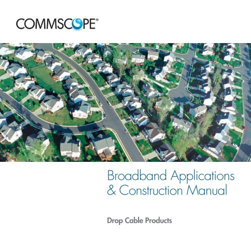
<strong>Broadband</strong> <strong>Applications</strong><br />
& <strong>Construction</strong> <strong>Manual</strong><br />
Drop Cable Products
Table of Contents<br />
Section 1 ................Introduction<br />
1.1 Forward<br />
1.2 Drop Cable Issues<br />
Section 2 ................Description of Cable Types<br />
2.1 Coaxial Cable Description<br />
2.2 The Importance of Braid Shielding<br />
2.3 UTP Cable Description<br />
Section 3 ................Cable Selection Guide<br />
3.1 Distance of the Drop<br />
3.2 Indoor/Outdoor and Shield Selection<br />
3.3 QR ® 320 Cable Types<br />
3.4 F11 Cable Types<br />
3.5 F6 Cable Types<br />
3.6 F11 Cable Types for NEC 830<br />
3.7 F6 Cable Types for NEC 830<br />
3.8 UTP and Fiber Optic Cables<br />
Section 4 ...............Planning the Run<br />
4.1 Overview<br />
4.2 Attachment Examples<br />
Section 5 ................Aerial Installation<br />
5.1 Overview<br />
5.2 Pulling Cable<br />
5.3 Span Attachment<br />
5.4 Connecting the Coax<br />
5.5 Attaching the Cable to the Residence<br />
5.6 Running to the Grounding Block<br />
Section 6 ................Buried Installation<br />
6.1 Overview<br />
6.2 Plowing Overview<br />
6.3 Trenching Overview<br />
6.4 Placement of the Pedestal<br />
6.5 Connecting the Drop<br />
6.6 Connecting the Drop<br />
Section 7 ................Attaching to the Ground Block per NEC 830<br />
7.1 Connecting to the Aerial drop<br />
7.2 Connecting to the Buried Drop<br />
Table of Contents 0.1<br />
Drop Cable <strong>Applications</strong> and <strong>Construction</strong> <strong>Manual</strong>
0.1 Table of Contents<br />
Drop Cable <strong>Applications</strong> and <strong>Construction</strong> <strong>Manual</strong><br />
Section 8 ................Attaching to the NIU per NEC 830<br />
8.1 Attaching to the NIU<br />
8.2 Connecting to the Buried Drop<br />
Section 9 ................Residential Interior Cabling<br />
9.1 Overview<br />
9.2 Planning and Pulling the Cable on the First Floor<br />
9.3 Cutting Outlet Holes<br />
9.4 Going Through an Exterior Wall<br />
9.5 Walls from Below<br />
9.6 Planning and Pulling the Cable on the Upper Floor<br />
9.7 Fishing Cable into Place<br />
9.8 Hiding the Cable<br />
9.9 Coax Connectorization<br />
9.10 QR ® 320 Connectorization<br />
9.11 Connectorization UTP Cable<br />
9.12 Trim-out and Finish<br />
Section 10 ..............Multiple Dwelling Units (MDUs)<br />
10.1 Overview<br />
10.2 Planning and Pulling the Cable<br />
10.3 One and Two Story Buildings<br />
10.4 Taller Buildings Outside<br />
10.5 Taller Buildings Outside<br />
10.6 Inside the Residence<br />
Section 11 ..............Commercial Installations<br />
11.1 Overview<br />
11.2 Wiring Schemes<br />
Section 12 ..............Drop Cable Descriptions/Specifications<br />
12.1 Specifications and Part Numbers<br />
Section 13 ..............Appendix<br />
13.1 Safety Overview<br />
13.2 OSHA and NEC Standards<br />
13.3 NEC and Other Ratings<br />
13.4 NESC Standards and <strong>Construction</strong> Grades<br />
13.5 Wire Clearance<br />
13.6 Pole Lease Agreements and Other Codes<br />
Section 14 ..............<strong>Broadband</strong> Resource Center
How to Use This Guide<br />
The Drop Cable <strong>Applications</strong> and <strong>Construction</strong> Guide is written for the cable installation professional who, due to<br />
the diverse services offered by CATV and telecommunication service providers, needs a quick and handy reference<br />
to practical installation information, especially in the case of retrofitting.<br />
We’ve tried to simplify the decision-making process as to which cables to choose for what installation, taking into<br />
account factors such as performance over distance, preventing RF interference and fire/safety codes.<br />
We also want to introduce you to some products that may ease some of your installation headaches, such as<br />
BrightWire ®<br />
anti-corrosion treatment for braid shields, and QR ®<br />
320, an ultra-long reach coaxial cable.<br />
One of the big changes in our industry is the introduction of powered broadband services, which are addressed in<br />
the National Electrical Code’s Article 830. This manual shows you when to use NEC 830 cables; sections 6 and<br />
7 cover specific issues involving installation clearances; other chapters carry special callouts concerning NEC 830<br />
issues.<br />
Most attention is paid to residential installations (section 9) which has the most ‘practical’ information, especially<br />
for trim-out. Sections 10 and 11 (MDU and commercial installations) are more general, and will refer you back to<br />
section 9 for the specifics of finishing out the installation.<br />
It is impossible to cover every single situation an installer may run into. These guidelines are no replacement for<br />
your good common sense and experience.<br />
Introduction 1.1<br />
Forward<br />
It’s always good to know that you have backup should you run into a difficult installation. If you find you need<br />
advice, call <strong>CommScope</strong>’s BRC (<strong>Broadband</strong> Resource Center TM<br />
) toll free at 866-333-3272 from<br />
9 am to 5 pm ET Monday through Friday. We’re always glad to help out a fellow professional.
1.2 Introduction<br />
Drop Cable Issues<br />
<strong>CommScope</strong> Drop Cable<br />
During the last years of the 20th century, new words were added to the vocabulary of both installers and subscribers<br />
of cable and telecommunications providers; terms like digital, broadband, multimedia and smart homes entered<br />
our everyday language. Coaxial cable, formerly a one-way conduit for TV, is now a two-way conduit for specialty<br />
programming, HDTV, stereo radio, internet access, telephony and more. And within the home and office, coaxial<br />
and UTP cables - even fiber optics - carry these services with a speed and clarity that were once thought impossible.<br />
Here in the 21st century, as providers of broadband services upgrade their plants to deliver<br />
the features demanded by millions of customers, we must keep in mind that the last<br />
mile, in fact the last few hundred feet of cable, is the essential component in the network.<br />
All of the digital high-speed gigahertz power promised by your company is nothing more<br />
than a dark screen if the cable that runs from the tap to the wall is poorly installed and<br />
connected.<br />
Coax, UTP, fiber optic - <strong>CommScope</strong> makes all of the cables that make the broadband<br />
revolution possible. That’s why we offer:<br />
for the system buyer, a selection of cables that perform under extreme conditions,<br />
including sun, heat, cold, moisture and heavy RF interference. We also offer cables that<br />
resist corrosion and meet critical riser and plenum standards for indoor installation.<br />
<strong>CommScope</strong><br />
delivers<br />
on the<br />
promise of<br />
broadband<br />
services<br />
with a<br />
family of<br />
high-speed<br />
craft-friendly<br />
cables<br />
for the craftsman, cables are available in convenient lengths with features that ease installation. We also offer<br />
toll-free technical assistance at 866-333-3272 if you need a fast answer on an installation issue.<br />
<strong>CommScope</strong> is proud of our 30+ year relationship with the cable installer. We know you’ll discover that<br />
<strong>CommScope</strong> cables deliver all the quality and features you need to make the digital revolution a success.
Coaxial Drop Cable<br />
The three types of cable used to carry broadband services to and within business and residences are coaxial, fiber<br />
optic and unshielded twisted pair (UTP). Coaxial (or coax) cable is the most common; it is the ‘cable’ in the term<br />
‘cable TV.’ The vast majority of broadband networks are constructed using some type of coaxial cable. Coax is<br />
made up of these basic components:<br />
The center conductor carries a low-voltage RF or electronic digital signal and may also carry up to 150 volts<br />
of power (see Safety Standards, Section 13.3). For optimum strength and performance, <strong>CommScope</strong> uses copperclad<br />
steel for our coax - other types (solid copper, silver coated copper clad steel) are available;<br />
The dielectric is a polymer insulation that supports the conductor. <strong>CommScope</strong> enhances the performance of its<br />
coax by using foamed (or cellular) dielectrics that offer lower loss;<br />
The shield defends the signal from RF interference. <strong>CommScope</strong><br />
uses a foil/aluminum wire braid combination for long-term protection<br />
and performance; our highest performance QR ®<br />
320 cables use<br />
a welded and bonded .013 in (0.3 mm) thick strip of aluminum as<br />
a shield. Shielding corrosion can be prevented with <strong>CommScope</strong>’s<br />
BrightWire ®<br />
treatment, and a braid shield impregnated with Migra-<br />
Heal ®<br />
flooding compound will resist moisture migration;<br />
The jacket protects the entire assembly. Jacketing materials will vary<br />
depending on the application - tough polyethylene (PE) is used for buried<br />
installations; lower smoke-and-flame producing polyvinyl chloride<br />
(PVC) is used aerially and indoors, as are plenum-rated fluorinated<br />
ethylene propylene (FEP) and polyvinylidene fluoride (PVDF).<br />
For aerial installations, a messenger wire is built into the cable for<br />
support. <strong>CommScope</strong> also offers Multi-Reach ®<br />
cables that add up to<br />
six voice-grade UTPs for discrete phone service or powering.<br />
Cable Descriptions 2.1<br />
Coaxial Cable Description<br />
copper-covered<br />
steel conductor<br />
foamed dielectric<br />
foil/braid shield<br />
combination<br />
messenger wire<br />
jacket
2.2 Cable Descriptions<br />
The Importance of Braid Shielding<br />
Braid Shielding and Coaxial Cable Performance<br />
A coaxial cable must have, at minimum, a dual shield of aluminum foil tape overlaid with a woven braid of aluminum.<br />
This braid shield greatly improves the electrical and mechanical performance of the coax;<br />
in fact, a braid shield can vastly increase the installed life of the cable. All <strong>CommScope</strong> subscriber access coaxial<br />
cables use a combination of foil and braid shields.<br />
Braid Shielding Provides Low Frequency Protection<br />
Foil shielding is usually a layer of aluminum bonded to a polyester tape. It provides<br />
100% coverage over the dielectric and is best at preventing ingress and leakage of<br />
high frequency signals; however, it is not that effective with lower frequency signals.<br />
Aluminum braid shielding complements foil by containing and preventing interference<br />
from those lower frequencies.<br />
Braid shields<br />
increase cable<br />
performance<br />
and can<br />
greatly extend<br />
the useful life<br />
of the cable<br />
Braid Shielding Helps Maintain DC Resistance<br />
Foil shielding is very flexible but lacking in mechanical strength. Stress caused by installation or by twisting and<br />
flexing over time (like in an aerial installation) will cause microscopic gaps to open in the foil. These ‘microcracks’<br />
degrade the electrical integrity of the foil and cause the DC resistance of the cable to rise. Resistivity gets worse as<br />
the cable twists.<br />
Strong, flexible braid shielding supports the foil and helps fight the formation of microcracks. The braid wires do<br />
not microcrack; they bridge the gaps in the foil. Braid shielding keeps its integrity and delivers low and constant<br />
resistivity numbers even when twisting and flexing.<br />
Braid Shielding Keeps Attenuation Low<br />
Attenuation performance goes hand in hand with DC resistivity; high resistivity caused by microcracks in the foil will<br />
result in higher attenuation. A history of 15,000 flexures can degrade a foil shield to the point where the calculated<br />
attenuation could worsen by 400% or more. However, the robust nature of the additional braid shield keeps attenuation<br />
low.<br />
Braid Shielding Keeps Connectors Connected<br />
The additional strength provided by braid shielding gives connectors something to hold onto. In terms of pulloff<br />
force, both compression and crimp-fitted connectors hold much tighter to cables with braid shields.
UTP Indoor Cable<br />
Unshielded twisted pair (UTP) cables consist of two insulated conductors twisted together in a very precise fashion;<br />
four of these pairs are then jacketed together into a cable. The angle and number of the twists acts like a shield<br />
and helps the digital signal stay robust over longer distances. UTP is used inside buildings to distribute voice and<br />
data signals over relatively short distances.<br />
Through advances in construction and materials, UTP cables have a much higher bandwidth (information carrying<br />
capacity) than their telephone wire cousins. Most UTP cables are defined by a ‘category’ or a performance designation.<br />
The categories are roughly determined by the bandwidth, or information-carrying capacity, of the cable.<br />
Category 5 (a data cable rated at 100 mHz of bandwidth) is the most commonly used type in residences. For<br />
higher data speeds and increased bandwidth, <strong>CommScope</strong> also offers Ultra II enhanced Category 5e (200<br />
mHz) and UltraMedia Category 6 (400 mHz) cables.<br />
Maintaining the twist is essential, especially during connectorization - the conductors must remain<br />
twisted right up to where they meet the jack. The loss of just one twist can degrade the performance of the cable so<br />
as to render it useless as a high-speed data cable.<br />
UTP cables consist of three basic components:<br />
The conductor is 23 or 24 AWG solid bare copper;<br />
The insulation is usually a solid PE (foamed for UltraMedia)<br />
with FEP used in plenum cables; and<br />
The jacket is a riser-rated PVC or plenum-rated FEP or PVDF.<br />
Because these cables are used indoors, pay special attention to<br />
the NEC rating of the application.<br />
Cable Descriptions 2.3<br />
UTP Cable Descriptions<br />
24 or 23 AWG<br />
solid copper conductors<br />
polyethylene<br />
insulation<br />
4 twisted pair<br />
components<br />
PVC jacket
3.1 Cable Selection<br />
Distance of the Drop<br />
Coax Selection Considerations - Distance<br />
Coax cable can be engineered for several levels of performance and cost-efficiency. For instance, a larger cable<br />
will carry a signal over a longer distance; additional shields provide more protection from interference. Your first<br />
consideration, however, is the overall distance of the drop. <strong>CommScope</strong> offers cables tailored for different distances:<br />
Maximum Attenuation @ 68°F<br />
QR ®<br />
320 F11 Series F6 Series<br />
MHz dB/100’ (dB/100m)<br />
5 0.24 (0.79) 0.38 (1.25) 0.58 (1.90)<br />
55 0.84 (2.76) 0.96 ( 3.15) 1.60 (5.25)<br />
83 1.07 (3.51) 1.18 (3.87) 1.95 (6.40)<br />
181 ( 1.60 (5.25) 1.75 (5.74) 2.85 ( 9.35)<br />
211 1.73 (5.68) 1.90 (6.23) 3.05 (10.00)<br />
250 1.86 (6.10) 2.05 (6.72) 3.30 (10.82)<br />
300 2.04 (6.69) 2.25 (7.38) 3.55 (11.64)<br />
350 2.25 (7.38) 2.42 (7.94) 3.85 (12.63)<br />
400 2.38 (7.81) 2.60 (8.53) 4.15 (13.61)<br />
450 2.52 (8.27) 2.75 (9.02) 4.40 (14.43)<br />
500 2.72 (8.92) 2.90 (9.51) 4.66 (15.29)<br />
550 2.85 (9.35) 3.04 ( 9.97) 4.90 (16.08)<br />
600 2.98 ( 9.78) 3.18 (10.43) 5.10 (16.73)<br />
750 3.34 (10.96) 3.65 (11.97) 5.65 (18.54)<br />
865 3.62 (11.88) 3.98 (13.05) 6.10 (20.01)<br />
1000 3.89 (12.76) 4.35 (14.27) 6.55 (21.49)<br />
F6 & F11 187 )<br />
lower numbers are better - plenum cables will have higher attenuation<br />
QR ®<br />
Ask yourself<br />
320 - these<br />
are our highest<br />
performance coax<br />
and are recommended<br />
for MDU<br />
usage (see section<br />
12) or extremely<br />
long runs with<br />
their .071 in (1.80<br />
three questions:<br />
what’s the<br />
distance,<br />
what’s the<br />
environment<br />
and how<br />
much shielding<br />
is needed?<br />
mm) copper-clad aluminum center conductor.<br />
F11 Series Cables - excellent-performing coaxial<br />
cables with a 14 AWG (1.63 mm) copperclad<br />
steel center conductor. They are recommended<br />
for use in runs of over 150 ft (45<br />
meters).<br />
F6 Series Cables - these are made for shorter<br />
runs, with an 18 AWG (1.02 mm) copper-clad<br />
steel center conductor. They are recommended<br />
for use in runs of 150 ft (45 meters) or<br />
less.<br />
These cables are available in constructions for aerial and buried outdoor installations. They are also available for<br />
residential and commercial indoor (general, riser and plenum) usage.
Coax Selection Considerations - Shielding and Environment<br />
Once you’ve determined which cable answers your need for signal over distance, you need to determine the type<br />
of cable you’ll need for the installation environment.<br />
For areas of possible RF interference, (pager antennas or other visible<br />
problem as outlined in Section 3.1, or if there is a history of customer comments<br />
concerning interference from ham radios, etc.), consider using a Tri-Shielded cable<br />
(foil/60% braid/foil) shield. The extra layer of foil provides additional protection<br />
against high-frequency RF signals at little additional cost. Super-Shield (Quad) cables<br />
(foil/60% braid/foil/40% braid) provide optimum protection against RF interference.<br />
Cable Selection 3.2<br />
Indoor/Outdoor and Shield Selection<br />
Tri-shielded<br />
cables offer<br />
excellent RF<br />
protection at<br />
reasonable cost<br />
For aerial installations, select a messengered cable (also called a figure-8 cable) with a polyvinyl chloride<br />
(PVC) jacket. The messenger wire is a steel wire that is webbed together with the coax. This wire supports the coax<br />
- under no circumstances should subscriber access coax be run without a messenger or lashed to a wire.<br />
For buried installations, select a polyethylene-jacketed cable with MigraHeal ®<br />
flooding compound to prevent<br />
moisture ingress in case of damage. Article 830 considerations (see page 13.3 and Buried Installation 6.1) make<br />
the use of cable pre-installed in conduit (<strong>CommScope</strong>’s ConQuest ®<br />
) very attractive.<br />
For cables that transition from outside to inside (from the ground block to the inside connection), select<br />
a CATV cable for residential use, or select a CATV or CATVR cable for commercial buildings.<br />
For commercial installations, CATVR riser and CATVP plenum cables are required in certain circumstances.<br />
A riser-rated cable may be run vertically between floors; plenum cables are designed for use in air-handling<br />
spaces, such as the area above a hung ceiling. General purpose cables (CATV) may be run horizontally within or<br />
along walls and in raceways - they cannot transition between floors.<br />
For locations where salt or other aerial corrosives may be a problem, <strong>CommScope</strong> offers two<br />
aerial cable anti-corrosive treatments for braid shields: BrightWire ®<br />
, a dry treatment that chemically combines with<br />
metal components to protect against corrosion (and improve DC loop resistance); and APD (Amorphous Polypropylene<br />
Drop), a non-flowing polypropylene flooding compound.
3.3 Cable Selection<br />
QR ® 320 Cable Types<br />
QR ®<br />
320 Series Selection Matrix (MDUs and Very Long Runs)<br />
This is a quick reference for QR 320 Series cables from <strong>CommScope</strong>. Answer the questions as you read along the<br />
diagram to arrive at the construction code for the cable required for your application.<br />
QR 320 cables have a unique welded aluminum strip shield for superior RF protection and a large center conductor<br />
for lower attenuation over longer distances. We recommend them for use in MDUs.<br />
Underground QR 320 cables use MigraHeal ®<br />
flooding compound which is applied under the jacket , making it<br />
suitable for direct burial. MigraHeal floodant is designed to flow into damaged jacket areas, sealing this area and<br />
inhibiting corrosion.
F11 Series Selection Matrix (Runs Over 150 ft/45 Meters)<br />
Cable Selection 3.4<br />
F11 Cable Types<br />
This is a quick reference for F11 Series cables from <strong>CommScope</strong>. Answer the questions as you read along the diagram<br />
to arrive at the construction code for the cable required for your application:<br />
The XX in the part number should be filled with the code for the anti-corrosion agent you’d prefer as follows: BW<br />
for <strong>CommScope</strong>’s dry BrightWire ®<br />
, or APD ®<br />
for the more traditional APD flooding compound.<br />
All non-plenum high RF cables are Tri-Shielded (foil/60% braid/foil); super-shield versions are available. Plenum<br />
cables are available only with super-shields.
3.5 Cable Selection<br />
F6 Cable Types<br />
F6 Series Selection Matrix (Runs 150 ft/45 Meters or Less)<br />
This is a quick reference for F6 Series cables from <strong>CommScope</strong>. Answer the questions as you read along the diagram<br />
to arrive at the construction code for the cable required for your application:<br />
The XX in the part number should be filled with the code for the anti-corrosion agent you’d prefer:<br />
BW for <strong>CommScope</strong>’s dry BrightWire ®<br />
, or APD ®<br />
for the more traditional APD flooding compound.<br />
All non-plenum high RF cables are Tri-Shielded (foil/60% braid/foil); super-shield versions are available. Plenum<br />
cables are available only with super-shields. A 90% braid is available for 2276K.
Cable Selection 3.6<br />
F11 Cable Types for NEC 830<br />
F11 Series Selection Matrix for NEC 830 (Runs Over 150 ft/45 Meters)<br />
This is a quick reference for F11 Series cables that meet NEC 830. Answer the questions as you read along the<br />
diagram to arrive at the construction code for the cable required for your application:<br />
The XX in the part number should be filled with the code for the anti-corrosion agent you’d prefer:<br />
BW for <strong>CommScope</strong>’s dry BrightWire ®<br />
, or APD ®<br />
for the more traditional APD flooding compound.<br />
All non-plenum high RF cables are Tri-Shielded (foil/60% braid/foil); super-shield versions are available. Plenum<br />
cables are available only with super-shields.
3.7 Cable Selection<br />
F6 Cable Types foro NEC 830<br />
F6 Series Selection Matrix for NEC 830 (Runs 150 ft/45 Meters or Less)<br />
This is a quick reference for F6 Series cables meeting NEC 830. Answer the questions as you read along the diagram<br />
to arrive at the construction code for the cable required for your application:<br />
The XX in the part number should be filled with the code for the anti-corrosion agent you’d prefer:<br />
BW for <strong>CommScope</strong>’s dry BrightWire ®<br />
, or APD ®<br />
for the more traditional APD flooding compound.<br />
All non-plenum high RF cables are Tri-Shielded (foil/60% braid/foil); super-shield versions are available. Plenum<br />
cables are available only with super-shields. A 90% braid is available for 2276K.
UTP and Fiber Optic Cables<br />
Cable Selection 3.8<br />
UTP and Fiber Optic Cables<br />
Two factors control the selection for UTP and fiber optic cables; the speed of the network they will support and the<br />
NEC rating required by the installation.<br />
For UTP cables within the home, <strong>CommScope</strong>’s Category 5e UTP (product code UH58760) offers more<br />
than enough bandwidth for most applications. These cables meet the NEC CMR (riser) designation.<br />
If you are installing UTP in a commercial application (or require higher performance in a residential<br />
application), see the chart below:<br />
For fiber optic cables within the home, we recommend a two-fiber interconnect with a riser rating using<br />
multimode fibers (construction code R-002-IC-6F-FSDOR). A plenum version is available.
4.1 Planning the Run<br />
Overview<br />
Planning the Run<br />
The time you take in examining the site prior to installation is well spent and can help you avoid problems later on.<br />
You need to be aware of issues such as right-of-way (ROW), where you will tap into the span, the distance of the<br />
run and where you will attach and bond the cable at the customer’s structure. Refer to Section 3/Cable Selection<br />
to determine what cable to use based on distance or NEC 830 considerations.<br />
Look for Antennas to Select Cable Shielding<br />
A 60% braid/foil shield works for almost all CATV installations. If you are installing<br />
cable intended for a more active, two-way service (internet, high-speed data), you<br />
should consider a Tri-Shielded cable. Cellular and pager towers produce radiation<br />
that tends to raise havoc with CATV channels 19, 20 and 21. Ham radio aerials<br />
may also signify a problem. Urban zones (like southern California or metropolitan<br />
New York) have inherently high levels of RF pollution. We recommend Tri-Shielded<br />
cables with a minimum of 60% braid for areas with high RF concentrations.<br />
Whether the<br />
installation is<br />
aerial or buried,<br />
a simple site<br />
survey now<br />
can prevent<br />
headaches later<br />
Know Your ROW (Right-Of-Way)<br />
The most direct route may not be the legal route. Make sure the route you’re planning runs ONLY over the customer’s<br />
property. Generally, you can follow a parallel path to power or phone lines. However, UNDER NO CIR-<br />
CUMSTANCES lash your drop to any other cable.<br />
Locate the Tap<br />
While most spans have taps located next to the poles, you may occasionally find a tap in mid-span. This may be<br />
helpful in avoiding ROW issues.<br />
Select Your Attachment Point for Ease of Bonding and Access<br />
NEC 820 specifies that coaxial cable must be bonded, preferably with the electrical. Therefore, try to attach the<br />
cable to the wall or corner nearest the meter. If that can’t be reached, an exterior cold water pipe (if the plumbing<br />
throughout the building and back to the main is entirely metal) or an existing ground rod will do. If these are<br />
impractical, you will have to hammer in a ground rod. In most cases, you will be selecting the cable entry point<br />
into the building; however, if the NIU is already in place, try to attach your cable as close to it as you can, keeping<br />
bonding considerations in mind.
Attachment Examples for Aerial Installations<br />
The top example shows a pretty<br />
straightforward installation. The electric<br />
meter is on the opposite side of the<br />
building from the span, so attachment<br />
near the the cold water tap is acceptable.<br />
The middle example shows that the<br />
most direct route would trespass on<br />
neighboring property. Therefore, the<br />
drop should be run along the span<br />
and then angle to the building, eventually<br />
running toward the meter and then<br />
back to the point of entry. Be sure to<br />
check mid-span; it is possible that there<br />
may be a tap there because a pole<br />
was there at one time.<br />
The bottom example is a tough call.<br />
It’s marginally shorter to attach near<br />
the point of entry, run to the meter for<br />
bonding purposes and double back to<br />
the point of entry.<br />
In all cases, check your local<br />
code requirements and<br />
system design specifications<br />
for your prescribed<br />
bonding requirements.<br />
Planning the Run 4.2<br />
Attachment Examples
5.1 Aerial Installation<br />
Overview<br />
Aerial Installation/Messenger (Figure-8) Cable<br />
For best efficiency and lowest cost, aerial installation is generally preferred. However, local or subdivision codes<br />
sometimes require that utilities be installed underground. There are times the customer may want the cables hidden<br />
for aesthetic reasons. In these cases, see Section 6 for instructions on buried installations.<br />
A typical installation is shown below. A continuous length of cable runs from the tap to the attachment point and<br />
continues to the grounding point, called a ground/bond block. A second cable continues from the ground block<br />
through the point of entry to a termination point within the structure.<br />
Article 830 Considerations<br />
Some systems use coaxial or UTP cable to carry power as well as signal to the NIU<br />
(Network Interface Unit - sometimes called a NID/Network Interface Device). When<br />
installing powered coax cable (carrying up to150 volts), pay special attention to the<br />
cable-to-earth distance as shown in the diagram below.<br />
NEC 830 also requires that cable attached to the building within 8 ft (2.5 m) of grade<br />
must be placed within conduit, raceway or some other approved cable guard.<br />
tech tip:<br />
when pulling<br />
and hanging<br />
cable, avoid<br />
twisting,<br />
scraping,<br />
stepping on<br />
or crushing it<br />
NIUs and Ground Blocks<br />
NEC 830 installations will terminate at an NIU. Most NIUs have built-in connections that must be grounded at the<br />
meter or other approved point. See Section 8/Attaching to the NIU per NEC 830.
Pull the Cable, Separate the Messenger<br />
Set up your cable pack or A-frame beneath the tap. Take the cable end and walk toward<br />
the attachment point. Don’t let the cable kink, scrape, tangle or get hung up as<br />
you walk - it may deform the cable and cause transmission problems later.<br />
Keep pulling cable after you reach the attachment point. Remember, you need to have<br />
enough cable in hand to run along the soffit or foundation line of the building to reach<br />
the grounding point.<br />
Go back to the reel and pull enough extra cable to reach the tap. Cut the cable at the reel.<br />
Separate the Messenger From the Coax<br />
Use your side cutters to start a split in the webbing<br />
between the messenger and the coax. Take the messenger<br />
in one hand and the coax in the other and<br />
smoothly pull your hands apart to split the webbing.<br />
Pull across the webbing (a scissors pull) instead of<br />
pulling the webbing directly apart.<br />
Connectorize the Cable<br />
Attach the connector per the instructions on page<br />
9.9/Coax connectorization.<br />
Aerial Installation 5.2<br />
Pulling Cable<br />
tech tip:<br />
always pull<br />
more cable<br />
than you<br />
think you’ll<br />
need
5.3 Aerial Installation<br />
Connecting to the Coax<br />
Connect the Coax to the Tap<br />
The cable should be connectorized per the instructions on page 9.9/Coax connectorization. Some systems like to<br />
protect the connection with a shield (a physical covering to protect against tampering). Place that over the connector<br />
now - you will require an F-connector tool to tighten the connection.<br />
With the messenger secured to the span, screw the connectorized cable into the tap hand-tight. Using a torque<br />
wrench, tighten the connector to 30 lbs/in. If you don’t have a torque wrench, twist the connector an extra 1/4<br />
turn with your wrench or F-connector tool to seat it. Cover the connection with a boot.<br />
You should have about 2 ft (60 cm) of cable between the tap and where the cable joins the messenger. Along<br />
with the ease of handling this provides, this extra cable will be very useful if you ever need to re-connectorize the<br />
cable.<br />
Store this cable by forming a loop of about 6 in (15 cm) in diameter. Make sure the diameter of the loop is no<br />
smaller than 10 times the outer diameter of the cable. Use cable ties to form and secure the loop to the span.<br />
Attach an identification tag to the cable.
Attach the Cable to the Residence<br />
Aerial Installation 5.4<br />
Attaching the Cable to the Residence<br />
Using a ladder or a lift truck, climb up to the attachment point and screw or drive the P-hook or Q-hook into the<br />
residence. Use an insulated hook if you are bringing in powered service per NEC 830. A good attachment point<br />
is the corner of the house under the soffit. NEVER attach to an antenna, rain gutter, chimney, power mast or lightning<br />
rod. The hook should be parallel to the ground.<br />
The attachment point should not be any closer than 4” (10 cm) from a telephone<br />
cable or 1 foot (30 cm) from a power line. Make certain you meet all<br />
clearance requirements.<br />
Taking the cable in hand, climb up to the attachment point. Pull the cable taut until<br />
the sag is 1% of the overall length of the drop (examples: for a 100’ run, the sag<br />
should be 1 foot; for a 50’ run, the sag should be 1/2 foot). Use your hand to<br />
mark the place on the cable where the cable and the hook meet while maintaining<br />
proper sag. DO NOT pull the cable through the hook or attach it to the hook.<br />
Select a point on the cable at least 1 foot (30 cm)<br />
beyond where the cable and hook would meet. Using side cutters, cut the messenger<br />
wire, being careful not to nick the jacket of the coax. Pull the messenger and<br />
the coax apart to produce over 1 foot (30 cm) of messenger. Shear, don’t tear the<br />
cable (see page 5.2).
5.5 Aerial Installation<br />
Running to the Ground Block<br />
Run the Cable to the Grounding Block or NIU<br />
Using the 2-4-4 method described on page 5.4, attach the messenger wire to the hook (or use a messenger wire<br />
clamp). Strip the remaining messenger wire from the coax.<br />
Route the cable from the attachment point to the grounding block or the entry point for the NIU. The path should<br />
follow the architectural details of the residence, running down at the corners and across at beams and seams in<br />
the siding.<br />
Use cable clips to attach the coax to the house. A variety of screw-in or nail-in clips are available for wood and<br />
masonry. Special snap-in clips are available for vinyl and aluminum siding. Never staple coaxial cable. Stapling<br />
will deform the dielectric and may damage the shield; in either case, a loss of performance will result and<br />
you will have to replace the cable.<br />
Place your first clip so as to allow for<br />
a small drip loop. Then place the clips<br />
about every 3 feet (1 meter) for vertical<br />
runs and no further apart than 18<br />
inches (.5 meters) on horizontal runs.<br />
Make sure you do not kink or bend<br />
the coaxial cable tighter than the recommended<br />
bend diameter (usually<br />
10x its outer diameter - check your<br />
cable specs to be certain). All coax<br />
connections to the grounding block or<br />
splitters must be horizontal.<br />
If connecting to a ground block, proceed<br />
to Section 7. If connecting to an<br />
NIU, proceed to Section 8.<br />
For NEC 830,<br />
use an<br />
insulated<br />
hook for<br />
attaching the<br />
messenger<br />
wire
6.1 Buried Installation<br />
Overview<br />
Buried Installation<br />
Underground service has become popular in many developments and subdivisions. <strong>Broadband</strong> services are<br />
brought in by buried cable, and accessed by pedestals which are usually at the property line.<br />
While the easiest way to run the cable is to trench or plow in a burial-grade coaxial cable to a minimum depth of<br />
12 in (.3 m), burying cable preinstalled in conduit is a far better method. Cable-in-conduit (CIC)<br />
offers greater physical protection against environment, abrasion, rocks, etc. than direct burial which can prolong<br />
the life of the cable. And, should the cable ever fail, it can be replaced without digging up the yard. CIC of 1/2<br />
in (13 mm) to 3/4 in (21 mm) is recommended. If you are directly burying cable without using conduit, you<br />
should use an 18 in (45 cm) length of it to protect the cable 6 in (15 cm) below and 12 in (30 cm) above grade<br />
where it emerges next to the residence.<br />
Article 830 Considerations<br />
Systems that use coaxial cable to carry up to 150 volts of power (as well as signal) to a NIU fall under NEC 830<br />
regulations. Pay special attention to the buried cable depth as shown in the diagram below. Note that CIC (HDPE<br />
conduit) doesn’t need to be buried as deeply as direct burial installations.<br />
Although NEC 830 permits the use of metal conduit, <strong>CommScope</strong> does not recommend its use. Problems with<br />
rust, water migration, and potential damage to the cable jacket due to cutting and scraping during installation<br />
are possible results of using metal conduit. Frozen water will crush cable in a metal conduit, but HDPE conduit<br />
will allow the ice to expand and save the cable.
Plowing Installation Notes<br />
Buried Installation 6.2<br />
Plowoing Overview<br />
Direct burial cable and cable-in-conduit (CIC) may be installed by trenching or plowing. When plowing, select a<br />
plow chute with a bend radius no smaller (and preferably larger) than the minimum bend radius of the cable or<br />
CIC you are installing. The chute width should be at least 1/2 inch (1.25 cm) larger in diameter than the cable/<br />
CIC.<br />
At the pedestal, dig a trench deep enough and at least twice the length of the plow blade/chute for the plow<br />
blade to enter it comfortably. A similar trench should be dug near the attachment point at the residence. The<br />
cable/CIC may pay-off from the front of the walk-behind plow or from a stationary reel along the route.<br />
Carefully pull enough cable/CIC through the blade to comfortably allow for connectorization. Once the blade is<br />
completely in the ground, manually feed the cable/CIC into the plow blade.<br />
In the walk-behind plow method, pay the cable/CIC over the top of the reel. Do not use reel brakes. In the stationary<br />
reel method, pull the cable/CIC end from the reel to the starting trench. With CIC, make sure both ends<br />
of the conduit are capped.
6.3 Buried Installation<br />
Trenching Overview<br />
Trenching Installation Notes<br />
The trench should be dug as straight, level and as rock-free as possible. Avoid tight curves. If there are rapid<br />
grade changes, and you are installing CIC, use back-fill to support the conduit. Taking into account NEC 820<br />
and 830 considerations, dig the trench to correct depth.<br />
Mount the reel so that pay-off is underneath toward the direction of the pull. If using CIC, make sure the conduit<br />
is capped.<br />
Pull enough excess cable to permit easy installation at the attachment point and enough to reach a few feet beyond<br />
the pedestal. When in doubt of the exact length, always play out more than you think you will need.
Pedestal Preparation<br />
Plowing<br />
Dig a receiving pit to the depth required by either NEC 820 or 830, depending on your application (between 12<br />
and 18 in (30 and 45 cm) (see page 6.2). The pit should be about 6 in (15 cm) wide and 18 in (45 cm) long and<br />
run in the direction of planned line of the installation. The plow blade should be able to fit easily inside it.<br />
Feed your cable or CIC through the plow blade and run it to the bottom of the pit and up through the pedestal<br />
base. The rule of thumb is to leave at least 10 times the outer diameter of the cable for easy connectorization and<br />
leaving some spare cable for connector replacement. If using CIC, tamp some dirt in as backfill support for the<br />
curve of the conduit.<br />
If you are using CIC, keep the end capped until you’ve initially placed the cable. Use a ratchet shear (such as the<br />
Reed RS#1) to trim off the excess conduit. Fill the conduit end with a watertight sealing foam.<br />
Trenching<br />
If trenching, unreel your cable or conduit as shown on page 6.2.<br />
The only difference is that you will not need a<br />
receiving pit, as you will already have the<br />
trench dug.<br />
Buried Installation 6.4<br />
Placement at the Pedestal
6.5 Buried Installation<br />
Connecting the Drop<br />
Running the Cable and Connecting the Drop at the Pedestal<br />
Plow to the Residence<br />
If you are plowing in the cable or CIC, make sure you have dug a receiving trench to the attachment point of the<br />
residence. Run the plow along your planned route to the attachment point. Remember that for NEC 830 considerations,<br />
cable not in conduit must be buried at a depth of 18 in (45 cm). You may not be able to run the tractor<br />
directly to the attachment point; if not, dig a larger receiving pit.<br />
Trench to the Residence<br />
If you are trenching the installation, dig a trench of correct depth from the pedestal to the attachment point on the<br />
residence (see chart on 6.1).<br />
Connectorize and Attach the Cable<br />
After the cable has been placed, connectorize the cable per the instructions on page 10.9/Coax Connectorization.<br />
Once the cable is connectorized, attach it firmly to the tap. Leave a loop of cable 10 times the outer diameter of<br />
the cable to allow for expansion and to leave extra cable should reconnectorization ever be required. Use the sealing<br />
sleeve to protect the connection from moisture.<br />
Attach an identification tag to the cable. This is<br />
especially important if there are multiple taps at the<br />
pedestal. Use a cable tie to secure the lower part of<br />
the cable to the pedestal in order to keep the cable<br />
out of any dirt or water. If you are using conduit,<br />
seal the end of the conduit with either a waterproof<br />
expanding foam or with a duct cap. Once the cable<br />
is connected and the connections sealed, close<br />
the pedestal.
Attach the Cable to the Residence<br />
Plow Installation<br />
Unreel the cable/CIC by hand until you have more than enough to reach the attachment point. Always err on the<br />
side of having too much cable.<br />
If you have installed CIC, determine how much conduit you need to reach the attachment point. Using a ratchet<br />
shear, cut off the excess conduit to reveal the cable. Attach the conduit to the wall by using U-clamps.<br />
If you are not using CIC, use an 18 in (45 cm) piece of HDPE or PVC conduit to protect the cable where it exits<br />
the earth. Place the conduit over the cable and run it down to the trench. Secure the conduit to the wall with Uclamps<br />
so that 6 in (15 cm) of cable is below grade and 12 in (30 cm) is above grade. Seal the end of the conduit<br />
with either a waterproof expanding foam or with a duct cap.<br />
Some installers favor an enclosure on the wall for the attachment point. If so, run enough conduit so as to touch<br />
the base of the enclosure, connecting the conduit using the enclosure manufacturer’s instructions.<br />
If connecting to a ground block, proceed to Section 7. If connecting to an NIU, proceed to Section 8.<br />
Buried Installation 6.6<br />
Connecting the Drop
7.1 Attaching to the Ground Block per NEC 830<br />
Connecting to the Aerial Drop<br />
Attach the Cable to the Ground Block/Aerial Installation<br />
NEC Article 820 states that the ground block should be attached to the wall as close as possible to the electrical<br />
meter. Both the ground wire and the coaxial cable connections should run horizontally. The grounding wire should<br />
be as straight as possible.<br />
The preferred bonding method is to attach the ground block’s bonding wire to the electrical<br />
meter ground wire with a wire not less than 14 AWG in size. For recommendations<br />
regarding ground wires sizes, please refer to the National Electric Code (NEC 820-40)<br />
or your local building code. If bonding the ground block to the meter is not possible,<br />
you may bond to an exterior metal cold water pipe running into the earth. As a last resort,<br />
you may drive an 8’ ground rod into the earth and attach the bonding wire to that,<br />
but you will need to ground ALL of the grounds of the residence to that rod.<br />
Special Circumstances for Mobile Homes<br />
Bond mobile homes at the electrical service tap. If there is no service tap, you may bond to the frame of the mobile<br />
home using a wire no smaller that 12 AWG. NEVER bond to the siding of a mobile home.<br />
Connectorize the Cable and Form a Loop<br />
tech tip:<br />
test the<br />
bond with<br />
a voltmeter<br />
to ensure it’s<br />
properly<br />
connected<br />
Once the bond is attached, cut the coax so that you have a<br />
sufficient amount to reach the ground block comfortably plus<br />
about another 1’ (30 cm). Connectorize the cable (see page<br />
9.9/Coax connectorization) and attach it to the ground block.<br />
Then form a 6 inch (15 cm) diameter loop and secure it with<br />
a cable tie. This extra cable will be useful if you ever need to<br />
re-connectorize the cable.
Run and Attach the Cable to the Ground Block/Buried Installation<br />
NEC Article 820 states that the ground block should be attached to the wall as close as possible to the electrical<br />
meter. Both the ground wire and the coaxial cable connections should run horizontally. The grounding wire<br />
should be as straight as possible.<br />
The preferred bonding method is to attach the ground block’s bonding wire to the<br />
electrical meter ground wire with a wire not less than 14 AWG in size. For recommendations<br />
regarding ground wires sizes, please refer to the National Electric Code (NEC<br />
820-40) or your local building code. If bonding the ground block to the meter is not<br />
possible, you may bond to an exterior metal cold water pipe running into the earth. As<br />
a last resort, you may drive an 8’ ground rod into the earth and attach the bonding wire<br />
to that, but you will need to ground ALL of the grounds of the residence to that rod.<br />
Special Circumstances for Mobile Homes<br />
Bond mobile homes at the electrical service tap. If there is no service tap, you may bond to the frame of the mobile<br />
home using a wire no smaller that 12 AWG. NEVER bond to the siding of a mobile home.<br />
Connectorize the Cable and Form a Loop<br />
Once the ground is attached, cut the coax so that you<br />
have a sufficient amount to reach the ground block comfortably<br />
plus about another 1’ (30 cm). Connectorize the<br />
cable (see page 9.9/Coax connectorization.) and attach it<br />
to the ground block, Then form a 6 inch (15 cm) diameter<br />
loop and secure it with a cable tie. This extra cable will be<br />
useful if you ever need to re-connectorize the cable.<br />
Attaching to the Ground Block per NEC 830 7.2<br />
Connecting to the Buried Drop<br />
tech tip:<br />
test the<br />
ground with<br />
a voltmeter<br />
to ensure it’s<br />
properly<br />
connected
8.1 Attaching to the NIU per NEC 830<br />
Attaching to the NIU<br />
Attaching to the NIU - The 8 Foot Rule<br />
NEC Article 830 covers the installation of cable from the tap to the connection of the NIU. NEC 830-rated<br />
cables supply the voltage that powers the NIU. The NIU then distributes the various signals coming in over the<br />
drop (CATV, internet, telephone service, etc.) onto the preferred cable and connections that branch from the NIU<br />
throughout the residence. These interior cables (NEC 820 coax, NEC 800 twisted pair, NEC 770 fiber optic)<br />
carry very low, if any, voltage.<br />
Pages 5.1 (aerial drop installation) and 6.1 (buried drop installation) discuss the distances required for a safe installation<br />
of NEC 830 cable and service to the residence.<br />
The 8 Foot Rule<br />
NEC 830 requires that powered broadband cables that are attached to a building within 8 feet (2.5 meters) of<br />
the finished grade must be protected by molding or conduit. If you are using CIC, this requirement is<br />
easily met by extending the conduit from the ground to the entry point.<br />
If you are using direct burial cable without<br />
conduit, you must run the cable in conduit<br />
starting 18 in (45 cm) below finished<br />
grade and finishing in contact with the<br />
NIU enclosure.<br />
With an aerial installation, the cable<br />
should be placed in conduit with a J-joint<br />
at the top to prevent water from getting<br />
into the NIU, and then run to the top of<br />
the NIU enclosure.
Bonding the NIU<br />
Bonding the NIU is similar to bonding a standard coax installation (see Section 7 - Attaching to the ground<br />
block). You should attach the NIU to the wall as closely as possible to the electrical meter. The bonding wire is<br />
attached to a point within the NIU enclosure. Specific bonding points will vary with each make of NIU, so please<br />
consult the manufacturer’s instructions. In all cases, the bonding wire should be as straight as possible and run<br />
horizontally to the attachment point at the meter.<br />
The preferred bonding method is to attach the NIU’s bond to the electrical meter ground wire with a wire not less<br />
than 14 AWG in size. For recommendations regarding ground wires sizes, please refer to the National Electric<br />
Code (NEC 820-40) or your local building code.<br />
If bonding the NIU to the meter is not possible, you may bond to an<br />
exterior metal cold water pipe running into the earth. As a last resort,<br />
you may drive an 8’ ground rod into the earth and attach the bonding<br />
wire to that, but you will need to attach all of the grounds of the residence<br />
to that rod.<br />
Connectorize the Cable and Attach it to the NIU<br />
Once the ground is attached, cut the coax so that you have a sufficient<br />
amount to comfortably reach the connection within the NIU plus about<br />
another 1’ (30 cm), similar to the pedestal attachment (see page 6.4).<br />
Connectorize the cable (see page 9.9) and attach it to the NIU. If the<br />
cable is entering from above, form a small drip loop below the connection<br />
of the cable and the NIU. This loop will be useful if you have to<br />
reconnectorize the cable in the future.<br />
Attaching to the Ground Block per NEC 830 8.2<br />
Connecting to the Buried Drop
9.1 Residential Interior Cabling<br />
Overview<br />
Overview<br />
By now, the drop has been run to the residence, attached and grounded at either the ground block or the NIU.<br />
How and where you enter the residence depends on the types of service that are going to be provided. If there is<br />
no NIU, you need to proceed from the ground block to the various locations around the residence, splitting the<br />
connections as you go. It may be to your advantage to use a ground block with a splitter so that two coax cables<br />
may be run in different directions. With an NIU, multiple and different cabling types may be used on the output<br />
side. A general rule is that CATV coax may be split, but phone and computer UTP should be home run to the<br />
NIU. Cable modems should be placed at the first split.<br />
Article 830 Considerations<br />
Powered broadband cable MUST be terminated to a grounded location at an NIU (see Section 8/Attaching to<br />
the NIU per NEC 830 for details). Except within the wall or in a conduit like commercial electrical cable, NEC<br />
830 cable may not extend any further than 50 ft (15.2 meters) within a residence.<br />
Use the Crawlspace, Basement or Attic to Run Cable<br />
For the ground floor, plan your installation so that the cable runs through the crawlspace or basement and then<br />
up through the floor or an interior wall to the outlets. For the upper floor, run up to and through the attic and<br />
then down through the walls to outlets.<br />
If the crawlspace or basement present problems,<br />
another option is to run the cable around the outside<br />
of the residence. Be sure to use an outdoorrated<br />
cable. Try to follow the architectural lines of<br />
the house and run the cable in places where the<br />
foundation meets the bottom of the exterior walls,<br />
or vertically along the corner trim, or under the<br />
soffit. You can bury cable next to the foundation<br />
(keeping in mind the burial depth per NEC 820).<br />
Avoid placing cable in direct sunlight, as that will<br />
accelerate cable aging. Consider a non-metallic<br />
raceway to hide and protect the exterior cable.
Planning the Cable Run/Ground Floor<br />
Outlet locations are dictated by customer requirements - put them where they want them.<br />
Visually inspect every proposed outlet location. Be aware of the locations of electrical<br />
wires, plumbing, HVAC ductwork and other impediments. Use a studfinder to locate studs.<br />
As you plan your drops to specific locations within the residence, work within the interior<br />
walls whenever possible. This way, you avoid installation headaches like trying to push<br />
cable through insulation or around windows.<br />
In the example floor plan, the CATV and phone connections in the kitchen should be run beneath the house, but<br />
can just as easily be reached by running the appropriate cable (coax for CATV and internet, twisted pair from the<br />
NIU for phone and in-home data networks) along the foundation of the residence and entering through the exterior.<br />
In this case, the homeowner’s concern for outside appearance should be your concern.<br />
The CATV outlet in the corner of the living room can be reached by an exterior run up to the eaves above the garage<br />
door and back down at the corner of the house.<br />
The CATV outlet on the interior<br />
wall is best reached by a home run<br />
back to the NIU through the crawlspace<br />
or basement. However, the<br />
coax cable could also be split from<br />
either of the two exterior connections.<br />
A splitter has one connection<br />
on the input side and two or more<br />
on the output side to evenly divide<br />
the signal between multiple cables.<br />
Residential Interior Cabling 9.2<br />
Planning and Pulling the Cable on the First Floor<br />
tech tip:<br />
shorter<br />
cable runs<br />
produce<br />
clearer<br />
signal
9.3 Residential Interior Cabling<br />
Cutting Outlet Holes<br />
Locating and Cutting Outlet Holes<br />
Once outlet locations are determined, cut the holes as required. Carefully check the area for any possible obstructions,<br />
such as wall studs, plumbing or electrical wires. Be aware that obstructions like windows or interior<br />
openings like kitchen passthroughs may cause problems with dropping cables from above. Pocket doors are another<br />
concern; make sure the planned outlet is outside of their open range. Keep an eye open for creative routes<br />
to hide cable, such as running within closets.<br />
Once you’ve settled on the precise locations, prepare to cut the holes<br />
(1) Mark the Location<br />
A communications outlet consists of the mounting bracket, the feet (which hold the bracket in the wall) and the<br />
faceplate. Using the mounting bracket as the template, trace a cutting pattern on the drywall, making sure there<br />
are no studs behind it. Match the orientation (vertical or horizontal) with the other outlets in the room and make<br />
sure your planned cut is level.<br />
(2) Cut the Opening<br />
Using a drywall knife, utility knife or saw, cut the opening. Do<br />
not install the bracket yet; the metal edges may damage the<br />
cable during pulling and installation.<br />
(3) Run the Cable<br />
Once the cable has been run, you may install the bracket and<br />
terminate the cable (see page 9.12/Trim out and finish).<br />
Other Wall Surfaces<br />
Older homes may have plaster and lathe walls that will require<br />
a small rotary saw, or a cutout tool to cleanly penetrate and cut. Masonry walls will require a surface-mounted<br />
box screwed into the brick and a cable raceway to hide the cable.
Going Through an Exterior Wall<br />
Survey the interior of the residence for the outlet location. Using a point of reference that is common to both the<br />
inside and the outside (such as the lower corner of a window pane), measure the vertical and horizontal distances<br />
to the center of the outlet location (example: 1.5 feet over and 1 foot down from the lower corner of the window).<br />
Check again for obvious interference from electrical outlets, wall studs, plumbing,<br />
etc. You may want to shut off any nearby electrical circuit, as accidental<br />
contact with live service may result in a fatal shock.<br />
From the outside, measure from the reference point and drill a thin pilot hole<br />
at a slight upward angle to prevent water from later seeping in through the<br />
hole. If you are going through masonry, use a masonry bit and drill through the<br />
mortar, not the brick. If the pilot hole checks out, enlarge the hole with a larger bit.<br />
Insert a feed-thru bushing.<br />
On the inside, cut the outlet opening in the drywall. Do not install<br />
the bracket yet; the metal edges may damage the cable during<br />
installation.<br />
Set your A-frame or cable box at the ground block/NIU and pull<br />
the cable with you to the entry point. Allow extra cable for running<br />
through the wall as well as forming a 5 in (13 cm) drip loop. Use<br />
cable clips to attach the cable to the foundation of the residence.<br />
Pass the cable through the bushing and through the hole in the<br />
drywall. Allow plenty of cable for termination. Form the drip loop<br />
and place your last fastener. Seal the bushing with RTV silicone or<br />
a similar weatherproof sealant.<br />
Residential Interior Cabling 9.4<br />
Going Through an Exterior Wall<br />
tech tip:<br />
use electrical<br />
outlet boxes to<br />
help find<br />
wall studs;<br />
they are<br />
attached to<br />
them
9.5 Residential Interior Cabling<br />
Walls from Below<br />
Crawlspace and Basement<br />
Prior to entering a crawlspace or an unfinished basement, look and make sure that your planned entry point is<br />
not blocked by plumbing or unexpected obstructions like spoil left during construction. It may be possible to bring<br />
the cable through the crawlspace entrance. If not, use a masonry bit to drill through the foundation. Insert a feedthru<br />
bushing and pull the cable through; allow plenty of extra cable for reaching the outlet on the main floor.<br />
In a finished basement, plan your point of entry as close to the ceiling as<br />
possible and drill from the inside. Place your feed-thru bushing and run the<br />
cable to the inside. With a hung ceiling, you may be able to run the cable<br />
on top of that, attaching the cable to floor joists. Otherwise, run the cable<br />
around the top edge of the room, and then cross to your ceiling entry parallel<br />
to the walls. Wire mold can be used to hide the cable.<br />
Finding the Wall From Below<br />
At the outlet location, trace and cut your outlet hole. Then use a stiff, sharp<br />
piece of wire to drill a pilot hole right at the base of the toe molding (to<br />
leave no sign of a pilot hole at all, remove the toe molding and drill from the base of the remaining molding or<br />
the drywall). When you feel you’ve broken through the floor, detach the wire from the drill and leave it<br />
in the floor.<br />
Go under the floor and locate the wire. Measure<br />
in about 1 in (2.5 cm) (more if you drilled in at a<br />
very steep angle) and, using a thin bit, drill a pilot<br />
hole straight up to make sure you’re in the wall. Enlarge<br />
the hole to accommodate the cable and pull<br />
through enough for easy connectorization.<br />
Use cable clips to attach cable to the floor joists.<br />
tech tip:<br />
when drilling, use<br />
the sharp, stiff wire<br />
used to hold floor<br />
insulation in place<br />
or a piece of<br />
coathanger -<br />
a drill bit will<br />
tear up carpet
Planning the Cable Run/Upper Floor<br />
Visually inspect the outlet locations for electrical wires, plumbing, HVAC ductwork, windows and other impediments.<br />
Use the interior walls whenever possible. This way, you avoid installation headaches like trying to push<br />
cable through insulation or around windows, or reaching under a roofline with a drill.<br />
In the example below, all of the outlets can be reached from the attic. The phone outlet in the home office can<br />
also be reached from the exterior by running a cable up to the eaves and then across and down to the outlet location<br />
(consider a coax/UTP combination cable for this location). For the interior CATV outlets, a home run back<br />
to the NIU is preferred, but the CATV line can be split and continued.<br />
Run the shortest distance possible, but avoid aisles and areas used for storage. You may need to run around the<br />
eaves, or even clip cable along the inside of the roof and come down a pillar.<br />
The attic is usually accessed from outside by running the cable up the corner of an exterior wall. Before you drill,<br />
inspect the attic and check for any obstructions or clutter. Running cable up from the crawlspace or basement is<br />
a better and far less obtrusive method of getting to the attic. There may be an existing chase, but you may need<br />
to ‘fish’ the cable up and alongside plumbing<br />
or HVAC ducting. See page 9.7 for<br />
instructions.<br />
If entering from the outside, drill your entry<br />
hole at the roofline or slightly above it at<br />
a slightly upward angle. Use a feed-thru<br />
bushing to prep the hole (see page 9.4 for<br />
details). Feed the cable through the bushing<br />
and over to the drop; take more cable than<br />
you’ll need. Remember to seal the bushing<br />
after the cable is pulled into place.<br />
Residential Interior Cabling 9.6<br />
Planning and Pulling the Cable on the Upper Floor
9.7 Residential Interior Cabling<br />
Fishing Cable into Place<br />
Using Fish Tape to Run Cable<br />
Once cable is run to the attic, it can be fished through interior walls to the outlet location. Fishing cable usually<br />
requires two people; one at the top to feed the fish tape and a helper to receive the tape. A pair of walkie-talkies<br />
is a big help during this process. Use a non-metallic fish tape to avoid electrical shock.<br />
Locate the Drop Point<br />
The top of the walls should be visible under the beams in the attic. You can locate the studs by looking for the<br />
nailheads on the cap, or top board, of the wall. Measuring from a common point, such as the exterior wall, will<br />
give you an approximate reference point. Drill through the wall cap.<br />
1) Fish the Tape<br />
Cut the opening for the outlet as in page 9.3. Run the fish tape through the hole and into the wall. The helper<br />
below should be able to hear the tape slide down the wall. It may be that you have entered the wrong wall cavity.<br />
If so, drill a new hole in the proper location. Once the tape has reached the outlet hole, have the helper tape a<br />
pull string to the tape. Retrieve the tape and the string.<br />
2) Attach the Cable to the String<br />
Tie the pull string to the fish tape, then use several turns<br />
of electrician’s tape to secure about 6 in (15 cm) of cable<br />
to the string. For easier pulling, build the tape up into a<br />
shape with tapered end.<br />
3) Pull the Cable Down<br />
While feeding the cable through the wall, have the helper<br />
gently but firmly pull the cable down to the outlet. If the<br />
cable snags, pull the cable back up and try again. Once<br />
the cable is at the outlet, untape it from the pull string and<br />
draw enough cable to make a connection.
Hiding Cable<br />
It is not always possible to run a cable to its planned location within the wall. If the locations cannot be changed,<br />
there are alternate methods of running and hiding cables.<br />
Under the Wallboard<br />
Many houses have a gap at the bottom of the wall that is covered by the floor molding. This gap is usually wide<br />
enough to provide a hidden cable path around a room.<br />
Floor molding usually consists of a toe molding and a baseboard. Both must be very gradually removed in sections.<br />
Toe molding is usually nailed in at an angle, so loosen it gently, prying about 18 in (50 cm) apart, both up<br />
from the floor and out from the wall. Place a cloth behind your prying tool so as not to damage the floor or wall.<br />
Baseboards are usually nailed straight in to the wall studs. Gently pry them a very small bit at a time away from<br />
the wall so as to evenly remove the entire board.<br />
Cable can now be run in the gap between<br />
the drywall and the floor. When you<br />
get to the outlet location, use a drywall<br />
knife to carve a vertical channel wide<br />
enough for the cable and about 2 in (5<br />
cm) in height. Make sure the molding is<br />
tall enough to cover the channel. Use a<br />
drill to enter the wall and pull the cable<br />
up to the outlet hole.<br />
Using Raceway<br />
Cable entering from the floor can be<br />
clipped to the wall and hidden with a<br />
covering molding. There are several commercial<br />
brands of raceway; some are<br />
nailed on, some are glued, some are selfadhesive.<br />
Consult the individual manufacturer<br />
for installation instructions.<br />
Residential Interior Cabling 9.8<br />
Hiding the Cable
9.9 Residential Interior Cabling<br />
Coax Connectorization<br />
Connectorizing Braid-Shielded Coax Cable<br />
These instructions refer to general practices. Exact instructions may vary with<br />
the maker of the tools and connectors you are using. Always refer to the<br />
manufacturer’s specifications.<br />
If you are going to use a boot to protect the connection at the<br />
tap, or if you are using a compression fitting with an independent<br />
sleeve, slide it over the cable end first. Strip the end of the coax cable by clamping your cable<br />
prep tool around the cable, making sure that the end of the cable is flush against the stop. Rotate the tool 3x<br />
clockwise, then 2x counterclockwise until you’ve achieved a clean cut.<br />
A clean cut will have a square<br />
end and the cable will have<br />
a round cross-section. The<br />
dimensions in the drawing are<br />
approximate; always check<br />
with your connector manufacturer<br />
for exact dimensions.<br />
If you are using a crimp-style or one piece compression<br />
connector, slide it over the cable end and use the crimping<br />
tool to firmly attach the connector. A good connection will have<br />
solid contact between the neck of the connector and the braid<br />
under it. The conductor should<br />
extend no more than 1/8 in (3<br />
mm) beyond the front edge of the<br />
connector.<br />
If you are using a two-piece compression connector,<br />
slide the main boot over the cable. Then slide the compression<br />
sleeve up to the back of the connector. Use the proper compression<br />
tool to compress the connector to the manufacturer’s specifications.<br />
Carefully bend<br />
the braid back<br />
over the jacket.<br />
On tri- and<br />
super-shield cables, there is an outer<br />
layer of tape; carefully trim that away.<br />
tech tip:<br />
use a braid brush to<br />
brush back the braid.<br />
It makes connector<br />
insertion easier
Connectorizing QR ®<br />
320 Solid Shielded Cable<br />
QR 320 cables have a solid aluminum shield instead of a braid/foil shield combination. The dielectric needs to<br />
be cored out by the use of special tools. While the process is described below, you may wish to contact<br />
<strong>CommScope</strong> Digital <strong>Broadband</strong> Resource Center (866-333-3272) for more information.<br />
A QR 320 coring tool, a file, a center conductor cleaning tool, wrenches sized for the connectors (adjustable<br />
wrenches are fine) and cable cutters are required. A hi-torque, low-speed drill or a ratchet are optional, but will<br />
speed the process. Wearing safety glasses and gloves is recommended.<br />
Prepare the cable by using the cable cutters to trim the cable to a smooth, round end.<br />
Residential Interior Cabling 9.10<br />
QR ®<br />
320 Connectorization<br />
Remove the proper amount of shield and dielectric with the QR 320 coring tool. Slide the cable into<br />
the tool until it stops. With slight forward pressure, twist the coring tool (either by hand or mechanically with the<br />
ratchet or drill) so that the blade begins to strip and core the cable. Continue to turn the coring tool until it spins<br />
freely - the tool has a preset stop that requires no adjustment. Clean the dielectric and shield residue from the<br />
tool.<br />
Clean the center conductor by using a non-metallic cleaning tool. Score the coating on the center conductor<br />
at the shield and scrape it toward the end of the conductor. The conductor is clean if the copper is bright and<br />
shiny. DO NOT USE A KNIFE or other metal tool as it may damage the copper cladding.<br />
Remove the correct amount of jacket with the QR 320 jacket removing tool. Slide the cable into the tool<br />
until the cable stops. Turn the tool clockwise to strip the jacket. Continue turning until it spins freely - the tool has<br />
a preset stop that requires no adjustment.Remove any MigraHeal ®<br />
compound that may be on the shield.<br />
Slide the shrink tubing over the cable end, then attach the connector according to the<br />
manufacturer’s instructions. Place and shrink the boot. NOTE: IF YOU ARE USING A HEAT-SHRINK BOOT<br />
(WHICH IS HIGHLY RECOMMENDED), APPLY THE FLAME CAREFULLY. Overuse of the torch may melt the<br />
jacket and dielectric.
9.11 Residential Interior Cabling<br />
Connectorization<br />
Connectorizing UTP and Telephone Cable<br />
These instructions refer to general practices. Exact instructions may vary with the maker of the tools and connectors<br />
you are using. Always refer to the manufacturer’s specifications.<br />
UTP - the Twist is Important<br />
Twisted pair cable twins its pairs together in a very precise lay, or frequency of twist. This lay provides a shielding<br />
effect that permits high-speed data signals to travel reasonably long distances with minimum interference. Maintaining<br />
that twist is essential to top performance, especially at the connector.<br />
The majority of UTP data connectors are of the Insulation Displacement Connector (IDC) type in an RJ45 size<br />
(eight wire). As the wires are crimped into place, the insulation is automatically stripped away to permit clean conductor<br />
contact. Other proprietary tools and methods exist; consult your connector maker.<br />
Use a ring tool to remove about 3 in (7.5 cm) of jacketing. Electrician’s snips can be used as long as you are<br />
careful not to nick or cut the insulation. This should expose four twisted pairs color-coded as pair 1/blue, pair<br />
2/orange, pair 3/green and pair 4/brown. When preparing the conductors for connectorization, do<br />
not untwist any more than 1/2 in (1.3 cm) of the pair.<br />
The two most popular UTP wiring schemes<br />
are TIA 568A and TIA 568B. It doesn’t matter<br />
which you choose as long as you are<br />
consistent throughout the installation. Place<br />
the conductors in the appropriate slots in<br />
the jack or the outlet (striped conductors in<br />
the odd slots, solid in the even) and crimp<br />
them into place with the appropriate crimping<br />
tool.<br />
Phone Wire<br />
Follow the same rules as UTP; instead use a standard 4-wire RJ11 jack. The color of the conductors going across<br />
are 1/yellow, 2/green, 3/red and 4/black.
Trim-Out and Finish<br />
With the cable run to the outlet, you can now trim out the installation.<br />
1) Insert the Bracket<br />
Most brackets are meant to install directly to the drywall. Place the cable through the bracket and insert the bracket<br />
in the wall. Insert the ‘feet’ at the bottom of the bracket so as to trap the drywall and the bracket. Tighten the<br />
attachment screw until the foot is firmly set. Repeat this process with the upper foot.<br />
2) Attach the Cable to the Faceplate<br />
Outlet faceplates will vary according to the cable type:<br />
Coax faceplates require that you terminate the cable with a connector and then screw that connector to the female<br />
connection on the faceplate. To prevent cable twisting, turn the faceplate when attaching it to the connector,<br />
or just make sure that you are turning only the hex nut of the connector and not the connector itself.<br />
UTP data faceplates require you to connectorize the cable to the jack. This is usually a separate component<br />
that snaps into the faceplate. Connectorize the cable like you did the jack on page 9.11, making sure you follow<br />
the same TIA568 pattern at all locations.<br />
Telephone jacks usually require you to strip back the insulation<br />
and screw the wires into marked locations on the back<br />
of the faceplate.<br />
3) Trim Out the Hole<br />
Once the cable is connectorized and attached, carefully<br />
place the excess cable into the hole, making sure that you<br />
do not exceed the bend radius or crimp the cable in any<br />
way.<br />
Residential Interior Cabling 9.12<br />
Trim-out and Finish
10.1 Multiple Dwelling Units (MDUs)<br />
Overview<br />
Overview<br />
Multiple Dwelling Units (MDUs) have a more strict set of rules for cable installation than single family residences.<br />
Service is dropped from the tap to the building like a residential installation, either aerially (see Section 6) or underground<br />
(see Section 7). However, the cable is usually run to some sort of interconnect box which allows the<br />
service provider to secure the connection and prevent tampering. This box may be inside or outside the building.<br />
A building with two or more apartments or condominiums is not considered to be a<br />
single-family residence and is governed by commercial building and safety regulations.<br />
For instance, you may need to use riser-rated cables instead of CATV rated residential<br />
cables. A general rule of thumb is if the cable penetrates the floor (if it runs vertically<br />
between floors), then you must use a riser-rated cble (CATVR for coax, CMR for UTP,<br />
OFNR for fiber). The riser cable is then run horizontally to the outlet (while you may use<br />
a lower rated cable for horizontal runs, the extra time and cost of termination outweighs<br />
the cost difference between the cables). You may use CATV cable inside metal conduit to<br />
pass between floors, though using a riser-rated cable is much easier.<br />
tech tip:<br />
review<br />
section 9<br />
for complete<br />
advice on<br />
running<br />
cables inside<br />
a structure<br />
Signal Amplification<br />
Another issue to consider is amplification. The signal being carried by the drop could be split literally dozens of<br />
times, thus decreasing its strength to the point where it is no longer viable. This is solved by installing a line amplifier<br />
before the crossconnection. While most amplifiers are powered by the voltage in the cable, some require connection<br />
to 110/120V power. Consult the directions from the manufacturer for specific powering instructions.<br />
The run from the crossconnect to the apartment could be several hundred feet. You may wish to consider upgrading<br />
your cable (example: from F11 to QR 320) or installing another line amplifier along the route.<br />
Article 830 Considerations<br />
The same rules apply concerning aerial distances (page 5.1), burial depth (page 6.1) and use of raceway or<br />
conduit within 8 ft (2.5 m) of the ground as residential installation. Article 830 also permits you to transition up to<br />
50 ft (15.2) meters of cable to meet an interior-mounted NIU. Longer runs require that the cable be run in metal<br />
conduit or within the wall like electrical wiring.
Planning the Cable Run in the Apartment<br />
Customer needs dictate where the outlets are located. Visually inspect every proposed outlet location. Be aware<br />
of potential problems like electrical outlets or HVAC ducting. You may not have the ability to drop cable from an<br />
attic or run up from a crawlspace, so your routing options may be limited. The preferred method would be to follow<br />
telecommunication conduit (if it exists) into the building. If not, consider the options shown below.<br />
From the Outside<br />
In the example floor plan, there are two ways to bring the cable in. The solid line shows running the cable from<br />
the exterior, entering the wall and running to the two locations. A suggested routing would be to bring the outdoor<br />
cable in at the ceiling line, run the cable along the top of the wall and split it there. Use methods described<br />
on page 9.4 to position the entry point correctly. You can run non-rated cables a maximum of 50 feet (15 meters)<br />
into an MDU; any further distance requires a CATV-rated cable. A CATV-rated cable is then either fished through<br />
or attached to the wall and concealed with wiremold to reach the outlet location. See Section 9 for specifics. The<br />
cable then continues along the top of the wall, over the door and through the interior wall to the second outlet,<br />
where it is either fished or attached to the wall and<br />
hidden with wiremold.<br />
From the Inside<br />
The dotted line shows a possible route from an interior<br />
hallway. Cable from a riser is run along the top<br />
of the hall wall and enters the apartment at the ceiling.<br />
Use methods described in section 9 to position<br />
the entry point correctly. The cable is split and either<br />
fished through the wall or attached to the outside of<br />
the wall. The cable continues along the top of the<br />
wall, over the door and around to the second outlet,<br />
where it is fished or run down to the outlet location.<br />
Multiple Dwelling Units (MDUs) 10.2<br />
Planning and Pulling the Cable
10.3 Multiple Dwelling Units (MDUs)<br />
One and Two Story Buildings<br />
One and Two Story MDUs<br />
For one or two story buildings, follow the same guidelines for running your cable as Section 9. A visual inspection<br />
of all proposed cable outlets is strongly recommended and will help you plan the best route for the cable.<br />
Use the Crawlspace, Basement or Attic to Run Cable<br />
For the ground floor, plan your installation so that the cable runs through the crawlspace or basement and then<br />
up through the floor or an interior wall to the outlets. For the upper floor, run up to and through the attic and<br />
then down through the walls to outlets.<br />
If the crawlspace or basement present problems, another option is to run the cable around the outside of the residence.<br />
Be sure to use an outdoor-rated cable. Try to follow the architectural lines of the house and run the cable<br />
in places like where the foundation meets the bottom of the exterior walls, or vertically along the corner trim, or<br />
under the soffit. You can even bury cable next to the foundation (keeping in mind the burial depth per NEC 820).<br />
Avoid placing cable in direct sunlight, as that will accelerate cable aging. Consider a non-metallic raceway to<br />
hide and protect the exterior cable.<br />
In this example, Apartment #1 is reached<br />
from the outside, running along the foundation<br />
and then upward to enter the wall.<br />
Apartment #2 is reached through the basement.<br />
Apartment #3 is reached through<br />
the attic. Apartment #4 is reached from<br />
the outside, with cable for #4 running up<br />
an architectural feature on the exterior wall.<br />
Riser-rated cable is being used for<br />
Apartments 2 and 3 since a floor is<br />
being penetrated.
Multiple Story MDUs/Riser Installation<br />
Multiple apartments, multiple floors, and the extra distances involved all contribute to the complexity of an MDU<br />
installation. A helper is mandatory. A system designer will be required to specify whether and where line amplifiers<br />
are needed. As always, make a thorough visual inspection of the proposed route and all outlet locations. It may<br />
be that exterior installation is the only option; if so, see page 10.5.<br />
Reaching the Crossconnect<br />
The drop should be grounded outside like a residential installation (see section 7/Attaching to the ground block).<br />
From here, a cable may be run to an exterior crossconnect or enter the building and attach to an internal crossconnect<br />
that could be within a wiring or telecommunications closet. If you are using a powered cable (NEC 830)<br />
you may run 50 feet (15 meters) into the building without using conduit; any longer distance requires the use of<br />
metal conduit or placing cable within the wall.<br />
Dropping Cable to the Closet<br />
Check with the maintenance personnel of the building to locate any chases,<br />
risers, ductwork or conduit being used by electrical wiring. DO NOT place<br />
coax cable in the same conduit as electrical cable (unless it is a divided<br />
conduit). In a riser, coax cable must be run at least 12 inches (30 cm) from<br />
electrical wiring. Sometimes, elevator shafts can be used. The important<br />
thing is to use 1) riser-rated cable and 2) a cable with the performance<br />
required to carry the signal over the distance from closet to outlet. It could<br />
be that you will need a higher performance cable for the interior installation<br />
than you used for the drop because of the longer internal installation<br />
distance.<br />
Set your cable reel or box near the riser entry point for the floor. Feed the<br />
cable down to a helper at the base of the riser. A congested telecommunications<br />
riser may require you to use fish tape to run the cable. See page<br />
9.7 for specifics on using fish tape. Remember, you need to drop a cable<br />
for each apartment, so make sure the riser can accommodate the total<br />
number of cables you’ll be using.<br />
Multiple Dwelling Units (MDUs) 10.4<br />
Taller Buildings Outside
10.5 Multiple Dwelling Units (MDUs)<br />
Taller Buildings Outside<br />
Multiple Story MDUs/Exterior Installation<br />
It may be simpler to run the cable on the outside of the building up to each floor or each apartment. A separate<br />
cable will be needed for every unit. As always, make a thorough visual inspection of the proposed route and all<br />
outlet locations.<br />
Prior to installing the cable, read page 9.4 for the methods needed to locate and drill your entry hole.<br />
Running Cable to Each Unit<br />
Use a ladder of greater height than required or a bucket truck to run the cable up the side of the building. Look<br />
for vertical and horizontal architectural elements that will help disguise the installation. Be sure you are using an<br />
outdoor-rated cable.<br />
Take the cable end with you up to the entry point.<br />
Form more cable that you will need (you can never<br />
use too much) into a loose loop. Tie off the loop with<br />
a cable tie and attach the cable to the building wall<br />
with a cable clip. Don’t let the loop hang free until<br />
you have at least two clips in the wall.<br />
Continue to attach the cable to the wall using clips<br />
every 3 feet (1 meter) until you reach the point where<br />
you want to turn downward. Being careful not to exceed<br />
the bend radius, attach the cable to the wall as<br />
you descend.<br />
Return to the entry point and enter the wall as described<br />
on page 9.4. Untie the cable loop and feed<br />
the cable through the hole.
Multiple Story MDUs/Inside the Building<br />
Multiple Dwelling Units (MDUs) 10.6<br />
Inside the Residence<br />
Unless you are able to share a conduit or routing with telecommunications wiring (you cannot run in the same<br />
conduit as electrical wiring unless the conduit is of the divided type), you may have to use a central hallway as<br />
your route. The challenge is to make the installation as unobtrusive as possible.<br />
Hallway Installation with Raceway<br />
The wall/ceiling joint offers a good route for interior installation. If there is a crown molding, carefully remove it<br />
(see page 9.8 for helpful hints). Starting from the riser, lay out the amount of cable needed to reach the apartment<br />
entry point. Calculate the amount of cable you’ll need inside the apartment and double it; this will help prevent<br />
coming up short inside and the possible reinstallation of the whole cable length. Cut the cable.<br />
At the riser, drill a hole for the cable to enter the hallway. Bring the cable and run it through the hole into the<br />
hallway and then back to the apartment. Use methods described on page 9.4 to position the entry point correctly.<br />
Use a stud finder to make sure you are drilling into a wall cavity. If possible, fish the cable down to the outlet location.<br />
Review Section 9 for details.<br />
Once all the cables have been run, replace the crown molding or use wiremold to cover the cables.<br />
Drop Ceilings/Plenums<br />
Cable can easily be laid on top of a suspended ceiling. However, the ceiling might be used as a plenum space<br />
(used for handling air for HVAC). If that is the case, you MUST either place the cable in metal conduit OR use a<br />
plenum-rated cable. See section 11/Commercial installation for details.
11.1 Commercial Installations<br />
Overview<br />
Overview<br />
Commercial installations differ from residential and MDU installations in several ways. Fire safety requirements are<br />
more strict. There may be cable raceways and ladders already in position to aid installation. The cable volume<br />
may be greater.<br />
The general scheme of bonding to an exterior point such as the electrical meter still holds. The cable then will<br />
probably transition inside to a wiring closet with a crossconnect box for distribution within the facility. Depending<br />
on the size of the building, this main closet may connect to subclosets in other parts of the structure, or on different<br />
floors. Like MDU installations, you may need to consult a design engineer about using line amplification, or<br />
may wish to upgrade to a longer reach cable such as QR 320.<br />
Wiring Closets<br />
Wiring closets (or telecommunication closets or TCs) can be rather complex. Literally hundreds of communication<br />
cables (phone, UTP, fiber) can be gathered here and interconnected through an array of patch panels and blocks.<br />
For specific instructions on connecting these types of cables, consult BICSI’s excellent volume Residential Network<br />
Cabling published by McGraw-Hill.<br />
Riser and Plenum Cables<br />
Any time a cable penetrates a floor (goes vertically between one or several floors), you must either use a riser-rated<br />
cable (CATVR) or install your cable in metal conduit. You can also use the plenum (air-handling) space above<br />
a dropped ceiling to run plenum-rated cables (CATVP) without using conduit. These cables are more flame-retardant<br />
and produce less smoke during a fire. Many office cubicle systems have built-in raceways that allow you to<br />
drop cables from the plenum ceiling directly to the desktop.<br />
Article 830 Considerations<br />
The same rules apply concerning aerial distances (page 5.1), burial depth (page 6.1) and use of raceway or<br />
conduit within 8 ft (2.5 m) of the ground as residential installation. Article 830 also permits you to transition up to<br />
50 ft (15.2 meters) of cable to meet an interior-mounted NIU. Longer runs require that the cable be run in metal<br />
conduit or within the wall like electrical wiring.
Wiring Schemes<br />
Commercial Installations 11.2<br />
Wiring Schemes<br />
A typical schematic for wiring a commercial installation is shown below. Coax cable transitions from the bonding<br />
point into the basement of the building and is attached to a crossconnect, probably in a wiring closet. Taking<br />
advantage of existing raceways and risers, riser-rated coax is pulled down the riser (or through the telecommunications<br />
conduit) from the higher floors. There, it is connected to a distribution panel and the horizontal cable runs<br />
are made.<br />
On the third floor, plenum-rated cable is run through the ceiling spaces and dropped to the desktops through<br />
custom raceways. It can also be dropped in the walls to outlets. On the second floor, CATV coax can be used to<br />
run along the walls to outlets. It can be concealed with wiremold. On the first floor, a short run of CATV cable is<br />
run behind the floor molding and carried across the floor, protected by a tread raceway.<br />
Due to the length of the long run to the far end of the building, a high-performance cable such as riser-rated<br />
QR ®<br />
320, is run up and over from the wiring closet and<br />
across the building via raceway or cable ladder. If it is in a<br />
metal conduit, a cable with a lower fire rating may be used.<br />
Avoid using plenum cables for longer runs as they tend to<br />
attenuate faster.
12.1 Drop Cable Descriptions/Specifications<br />
Specifications and Part Numbers<br />
Drop Cable Descriptions<br />
In Section 2, the various types of subscriber access cables were generally discussed. This section details the<br />
differences in the varieties of coaxial cable used outside and inside the residence.<br />
The construction examples given in the previous chapters deal with the most helpful types of coax;<br />
QR ®<br />
320, 11 Series (RG 11) and 6 Series (RG6). Commscope offers other types of coax as well, tuned to<br />
various uses within the residence. The full listing of our offerings includes:<br />
QR ®<br />
320 for longest reach and highest performance applications. The large 0.071 in (1.80 mm) coppercovered<br />
solid aluminum conductor is coupled with a welded aluminum shield for maximum performance;<br />
F11 series, recommended for use in runs of over 150 ft (45 meters), with a 14 AWG/1.63 mm copperclad<br />
steel center conductor and a standard foil/60% braid construction. Tri-shield (foil/60% braid/foil) and<br />
Super-Shield (foil/60% braid/foil/40% braid) versions are available;<br />
F6 series, recommended for use in runs of 150 ft (45 meters) or less, with an 18 AWG/1.02 mm copperclad<br />
steel center conductor and a standard foil/60% braid construction. A foil/90% braid, Tri-Shield (foil/60%<br />
braid/foil) and Super-Shield (foil/60% braid/foil/40% braid) versions are available;<br />
F59 series, recommended for very short runs, has an 0.032 in (0.81 mm) copper-clad steel center conductor<br />
and a standard foil/67% braid construction. A foil/95% braid, Tri-Shield (foil/67% braid/foil) and Super-<br />
Shield (foil/53% braid/foil/35% braid) versions are available;<br />
For further information on any of these cables, go to our website at www.commscope.com and download<br />
spec sheets, or call us at 1-800-982-1708 (1-828-324-2200 outside the US).
Drop Cable Safety Issues<br />
<strong>Construction</strong> of a broadband cable system requires a substantial amount of manpower, tools and equipment. Underground<br />
and aerial construction will expose the manpower, tools and equipment to hazards, dependent on field<br />
conditions and circumstances.<br />
The Occupational Safety and Health Administration (OSHA) defines a qualified employee as “any worker who by<br />
reason of training and experience has demonstrated his ability to safely perform his duties.” Only a qualified employee<br />
should be assigned duties that could cause harm or potential harm to the construction crew, general public,<br />
cable plant, and other utilities.<br />
This manual cannot identify the many hazards that exist in the construction environment, nor can it dictate the caution<br />
required with all of the tools, equipment and field conditions. <strong>CommScope</strong> continues this manual with the assumption<br />
that the construction personnel performing the work are qualified employees.<br />
Three sets of national codes and standards apply to the construction of cable systems.<br />
Section 1910.268 of the OSHA Safety and Health Standards applies to work in telecommunications<br />
centers and field installations. The National Electric Code (NEC) applies to<br />
building utilization wiring, i.e. inside plant construction. The NEC applies specifically, but<br />
is not limited to, plant that is within or on public and private buildings or other structures.<br />
The National Electric Safety Code (NESC), generally applies to outside plant construction.<br />
Municipal, state, county, and local codes are often applied to the construction of cable<br />
systems or work that involves their respective properties and right-of-ways. Pole Lease<br />
Agreements often stipulate specific practices related to safety.<br />
Appendix 13.1<br />
Safety Overview<br />
The ability<br />
to recognize<br />
and avoid<br />
hazards is<br />
required<br />
of all<br />
construction<br />
personnel<br />
These codes, regulations, and specified practices should be investigated, interpreted, communicated and observed.
13.2 Appendix<br />
OSHA and NEC Standards<br />
Occupational Safety and Health Administration (OSHA) Standards<br />
OSHA Standards were established in 1970 to help ensure workplace safety. The Standards are federal regulations<br />
that are intended to enable employers and employees to recognize, understand, and control hazards in the workplace.<br />
Standards have been established for general industry while some sections of the Standards are dedicated to<br />
specific industries such as telecommunications.<br />
The generally applicable OSHA standards are found in:<br />
Title 29 CFR Parts 1901.1 to 1910.441 General Industry, (OSHA), Order No. 869-019-00111-5<br />
Excavations (OSHA 2226), Order No. 029-01600125-5<br />
Underground <strong>Construction</strong> (Tunneling) (OSHA 3115)<br />
Stairways and Ladders (OSHA 3124)<br />
Copies of OSHA standards can be obtained from:<br />
Superintendent of Documents<br />
U.S. Government Printing Office<br />
Washington, DC 20402<br />
(202) 783-3238<br />
National Electric Code (NEC) Standards<br />
The NEC typically identifies the construction techniques and materials necessary in building wiring requirements,<br />
i.e., inside plant construction, of fiber optic or coaxial cable systems. The NEC has been developed by the National<br />
Fire Protection Association’s (NFPA’s) National Electric Code committee. Committee members are professionals<br />
from the electrical industry. The NEC addresses safety from fire and electrocution. The NEC has been adopted by<br />
the American National Standards Institute (ANSI).<br />
Copies of NEC standards can be obtained from:<br />
National Fire Protection Association<br />
1 Batterymarch Park/P.O. Box 9146<br />
Quincy, MA 02269-3555<br />
(800) 344-3555
NEC Articles 820 and 830<br />
NEC articles 820 and 830 both deal with broadband coaxial cable. Traditional coax networks carry a low-voltage<br />
radio frequency (RF) signal. The voltage is so low that it is not considered dangerous. NEC article 820 is written<br />
with fire safety, not voltage, in mind.<br />
However, with the advent of multiple services available over coax systems, the need for powered coax or UTP has<br />
risen. Some of these newer services require that a network interface unit (NIU) be installed at the subscriber’s residence<br />
with the NIU being powered via the cable. Generally, if there is a NIU involved, the cable will have to be<br />
rated for NEC 830.<br />
Basically, higher voltage NEC 830 cables need to be installed to provide greater protection<br />
for people than NEC 820 cables. Refer to the charts in Section 4.1/Aerial Installation or 5.1/Buried Installation<br />
for specific distances.<br />
Look for the cable rating on the jacket. The cable ratings are:<br />
Plenum-rated cables, designed for use in plenums, ducts<br />
and air handling spaces, carry the strictest NEC rating.<br />
Riser-rated cables are used in vertical shafts that penetrate<br />
more than one floor.<br />
General purpose-rated cables may be used in locations<br />
other than plenums or risers.<br />
Residential-rated cables are for use in one, two and multifamily<br />
dwellings and in raceways.<br />
Buried cables are for use underground alone or in conduit.<br />
This rating only concerns NEC 830 applications.<br />
Appendix 13.3<br />
NEC and Other Ratings
13.4 Appendix<br />
NESC Standards and <strong>Construction</strong> Grades<br />
National Electric Safety Code (NESC) Standards and <strong>Construction</strong> Grades<br />
The NESC defines grades of construction on the basis of strength requirements for reasons of safety. Section 24 of<br />
the NESC identifies construction grades B (the highest), C, D and N (the lowest).<br />
Grade D construction typically applies to broadband coaxial cable and fiber optic cable. <strong>Construction</strong> grades B<br />
or C may be applicable dependent on the situations that exist. If more than one grade of construction applies to<br />
a situation, the higher grade will apply. A qualified engineer should evaluate required construction and dictate the<br />
grade of construction. The strength requirements for the various grades of construction are defined within Section<br />
26 of the NESC.<br />
The NESC typically identifies the construction techniques and materials necessary in outside plant construction of<br />
electric supply or communication cable systems.The NESC is an American National Standard that has been written<br />
by a group of professionals that are concerned about the Standard’s scope and provisions. The NESC has been<br />
adopted by the American National Standards Institute (ANSI). All references to the NESC in this manual are from<br />
the 2002 edition.<br />
Special attention should be given to NESC Table 232-1, Vertical Clearance of Wires, Conductors, and Cables<br />
Above Ground, Roadway, Rail, or Water Surfaces which is reproduced in part on the next page.<br />
Copies of NESC standards can be obtained from:<br />
IEEE Service Center<br />
445 Hoes Lane/P.O. Box 1331<br />
Piscataway, NJ 08855-1331<br />
(800) 678-4333
NESC Table 232-1/Vertical Clearance of Wires<br />
This chart shows the clearances required for a coaxial cable, isolated communication conductors and cable, messengers<br />
and surge-protected wire meeting NESC Rule 230C1, depending on the type of surface it is above. For a<br />
complete listing, please contact the NESC at the address on page 3.4:<br />
Surface<br />
Minimum Distance<br />
feet (meters)<br />
Railroad tracks<br />
(except electrified railroads using overhead trolley conductors) 23.5 (7.2)<br />
Roads, streets, and other areas subject to truck traffic 15.5 (4.7)<br />
Driveways, parking lots and alleys 15.5 (4.7)<br />
Other land traversed by vehicles,<br />
such as cultivated, grazing, forest, orchard, etc. 15.5 (4.7)<br />
Spaces and ways subject to pedestrians or restricted traffic only 9.5 (2.9)<br />
Water areas not suitable for sailboating or where sailboating is prohibited 14.0 (4.0)<br />
Water areas suitable for sailboating with an unobstructed surface area of:<br />
Less than 20 acres 17.5 (5.3)<br />
Over 20 to 200 acres 25.5 (7.8)<br />
Over 200 to 2000 acres 31.5 (9.6)<br />
Over 2000 acres 37.5 (11.4)<br />
Land adjoining water areas posted for rigging or launching sailboats<br />
with an unobstructed surface area of:<br />
Less than 20 acres 22.5 (6.8)<br />
Over 20 to 200 acres 30.5 (9.3)<br />
Over 200 to 2000 acres 36.5 (11.1)<br />
Over 2000 acres 42.5 (12.9)<br />
Appendix 13.5<br />
Wire Clearance
13.6 Appendix<br />
Pole Lease Agreements and Other Codes<br />
Pole Lease Agreements and Other Codes and Regulations<br />
Pole Lease Agreements<br />
Cable system operators often enter into contractual agreements with the owners of utility poles. The pole owners<br />
are municipalities, telephone companies, and power companies. There are often specific safety practices that are<br />
specified in the contract. These safety practices may be more restrictive than other codes and standards. The contractual<br />
agreements should be investigated for safety requirements. The requirements should be interpreted, communicated<br />
and accordingly observed.<br />
State, Local, and Municipal Codes<br />
State, local and municipal codes may also apply to the construction of the cable system.<br />
These codes will vary by location. These codes will have to be identified and applied<br />
as required on a location specific basis.<br />
Governing Code or Regulation<br />
The more restrictive code or regulation must always be practiced.<br />
The most<br />
restrictive code<br />
or regulation<br />
is the one<br />
that must<br />
be practiced
<strong>Broadband</strong> Resource Center...<br />
Your One Stop Source for Cable Information<br />
Responsive support and literally years of deployment experience make <strong>CommScope</strong> a unique build-out partner<br />
capable of walking you through broadband logistics each step of the way. To design and maintain high-speed,<br />
complex networks you’ll need advanced levels of expertise. We realize that getting your technical personnel prepared to<br />
ascertain system requirements, understand engineering issues, select and install<br />
cable is not an insignificant hurdle. <strong>CommScope</strong>’s <strong>Broadband</strong> Resource Center<br />
exists to help you overcome these obstacles. Our staff has skill sets from the RF,<br />
telephony, optical and Internet worlds. We have a menu of services to help you<br />
develop technical competence and leadership within your own staff.<br />
Building a reliable, future-proof broadband network requires not only the best<br />
technology, but also experience and assistance in deploying that technology.<br />
<strong>CommScope</strong>’s <strong>Broadband</strong> Resource Center stands ready to assist you in your<br />
goal – the timely and cost effective deployment of state-of-the-art broadband<br />
services.<br />
<strong>Broadband</strong> Resource Center TM 14.1<br />
Our management and technical staff represents over a century of combined experience in coaxial, fiber optic and<br />
copper cable engineering and deployment. Members of <strong>CommScope</strong>’s <strong>Broadband</strong> Resource Center team hold several<br />
patents and have been published in a variety of industry publications.<br />
Active In Your Industry<br />
Our employees are involved in industry trade groups such as<br />
Society of Cable Telecommunications Engineers (SCTE), National<br />
Cable Television Association (NCTA), Women In Cable and<br />
Telecommunications (WICT), Custom Electronics Design and<br />
Installation Association (CEDIA) and Home Builders Association<br />
of America (HBA).
14.2 <strong>Broadband</strong> Resource Center TM<br />
Technical Services & Tools<br />
Access to the <strong>Broadband</strong> Resource Center affords access to the a wide array of services and tools:<br />
On-site Custom Training<br />
Includes courses such as:<br />
• Installation and Splicing<br />
• <strong>Construction</strong> logistics<br />
• <strong>Broadband</strong> concepts<br />
Training Collateral – all available FREE,<br />
just call Customer Service and request!<br />
• Comprehensive product catalogs<br />
• Industry standard construction manuals<br />
(Now available in English & Spanish!)<br />
• Training videos available in DVD format<br />
(Now available in English & Spanish!)<br />
• Published articles<br />
• White papers<br />
• Internet web site access to all product<br />
specification sheets<br />
• Attenuation slide rules<br />
• Specification assistance / review<br />
• International experience<br />
• Multilingual services available<br />
Engineering Services<br />
• Laboratory analysis<br />
• Standards committee support<br />
• Field trials and troubleshooting support<br />
• Sag and tension analysis<br />
Call Center Support<br />
Get advice such as:<br />
• What products to order<br />
• How to plan for construction<br />
• What to expect along the way<br />
For more information about our <strong>Broadband</strong> Resource Center or for information on products,<br />
please contact us by phone at 1-866-333-3272 or send us an e-mail at brc@commscope.com.
1100 <strong>CommScope</strong> Place SE • P.O. Box 1729<br />
Hickory, North Carolina 28603 • Tel: 1.866.333.3272 (3BRC)<br />
brc@commscope.com • www.commscope.com<br />
©2011, <strong>CommScope</strong> Inc. All Rights Reserved. • 12.07