PC PARALLEL PORT TO OS-LINK INTERFACE - DataSheet Seekic ...
PC PARALLEL PORT TO OS-LINK INTERFACE - DataSheet Seekic ...
PC PARALLEL PORT TO OS-LINK INTERFACE - DataSheet Seekic ...

You also want an ePaper? Increase the reach of your titles
YUMPU automatically turns print PDFs into web optimized ePapers that Google loves.
®<br />
<strong>PC</strong> <strong>PARALLEL</strong> <strong>PORT</strong> <strong>TO</strong> <strong>OS</strong>-<strong>LINK</strong> <strong>INTERFACE</strong><br />
FEATURES<br />
• Desktop mounted parallel port to differential<br />
<strong>OS</strong>-Link interface<br />
• Standard 25 way D-type parallel port connection<br />
• Standard 26 way D-type differential <strong>OS</strong>-Link<br />
connection<br />
• Plug top power supply<br />
• Supports nibble, byte and EPP mode parallel<br />
port standards<br />
January 1996<br />
ST20-PPI<br />
PRODUCT INFORMATION<br />
DESCRIPTION<br />
The ST20-PPI parallel port to <strong>OS</strong>-Link interface is<br />
a host interface to allow connection from a <strong>PC</strong> parallel<br />
port to any <strong>OS</strong>-Link based ST20 development<br />
board such as the ST20450-SAB. The interface<br />
plugs into any standard <strong>PC</strong> 25 way D-type parallel<br />
port. Supported parallel port modes are:<br />
• Nibble mode<br />
• Byte mode<br />
• EPP mode<br />
depending on which mode the host <strong>PC</strong> can support.<br />
Connection to the development target is via a<br />
differential <strong>OS</strong>-Link connector, as used on the IMS<br />
B300 and ST20450-Development Board. Once<br />
connected, the development target can be accessed<br />
with the standard ST20 Toolset using the<br />
MS Windows drivers supplied.<br />
1/6<br />
42 1679 00
ST20-PPI <strong>PC</strong> Parallel Port to <strong>OS</strong>-Link Interface<br />
1 Introduction<br />
The ST20-PPI parallel port to <strong>OS</strong>-Link interface is a host interface to allow connection<br />
from a <strong>PC</strong> parallel port to any <strong>OS</strong>-Link based ST20 development board such as the<br />
ST20450-SAB. The interface plugs into any standard <strong>PC</strong> 25 way D-type parallel port.<br />
Supported parallel port modes are:<br />
• Nibble mode<br />
• Byte mode<br />
• EPP mode<br />
depending on which mode the host <strong>PC</strong> can support. Connection to the development<br />
target is via a differential <strong>OS</strong>-Link connector, as used on the IMS B300 and ST20450-<br />
Development Board. Once connected, the development target can be accessed with<br />
the standard ST20 Toolset using the MS Windows drivers supplied.<br />
2 Installation<br />
2.1 Hardware Installation<br />
The ST20-PPI has three connections: Parallel port; Differential <strong>OS</strong>-Link and Power<br />
supply. To install the hardware, the following steps should be followed:<br />
• Plug the 25-way D-type of the parallel port cable built into the interface, into the<br />
parallel port of the <strong>PC</strong><br />
• Plug the target development system into the 26-way D-type using a differential<br />
<strong>OS</strong>-Link cable or the differential-to-single ended cable depending on the link<br />
interface available on the target board<br />
NOTE: To comply with EMC regulations this cable must use shielded cable<br />
with shielded headshells at either end.<br />
• Plug power supply cable into PSU socket of the interface<br />
• Plug the power supply into the mains socket.<br />
• Switch on the <strong>PC</strong><br />
• Switch on the power supply. The power LED on the interface should illuminate<br />
when the power supply is switched on<br />
2/6<br />
®
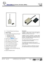
<strong>PC</strong><br />
Parallel port<br />
cable<br />
To mains<br />
adaptor<br />
2.2 Software Installation<br />
®<br />
ST20-PPI <strong>PC</strong> Parallel Port to <strong>OS</strong>-Link Interface<br />
ST20-PPI<br />
Differential<br />
Cable<br />
Figure 2.1 ST20-PP1 connections<br />
Development<br />
Target e.g.<br />
ST20450-SAB<br />
For installation of the DLL and VxD drivers, please refer to the ST20 Toolset software<br />
installation documentation.<br />
3/6
ST20-PPI <strong>PC</strong> Parallel Port to <strong>OS</strong>-Link Interface<br />
3 Connectors<br />
3.1 Differential Link Connector<br />
4/6<br />
Pin Description Pin Description<br />
1 +notSSDownReset 14 GND<br />
2 +notSSDownAnalyse 15 GND<br />
3 +notSSDownError 16 GND<br />
4 +notSSUpReset 17 GND<br />
5 +notSSUpAnalyse 18 GND<br />
6 +notSSUpError 19 -notSSDownReset<br />
7 +LinkOut 20 -notSSDownAnalyse<br />
8 +LinkIn 21 -notSSDownError<br />
9 GND 22 -notSSUpReset<br />
10 GND 23 -notSSUpAnalyse<br />
11 GND 24 -notSSUpError<br />
12 GND 25 -LinkOut<br />
13 GND 26 -LinkIn<br />
3.2 Power Supply Connector<br />
Table 3.1 26 way D-type connector<br />
The ST20-PPI uses a 2.5mm power connector. The voltage range is 8-13V dc.<br />
+V<br />
®<br />
GND
3.3 Parallel Port Connector<br />
4 Field Support<br />
®<br />
ST20-PPI <strong>PC</strong> Parallel Port to <strong>OS</strong>-Link Interface<br />
Pin Description Pin Description<br />
Table 3.2 Parallel port connector pinout<br />
SGS-THOMSON Microelectronics Limited products are supported worldwide through<br />
Sales Offices and authorized distributors.<br />
5 Ordering information<br />
1 notWRITE 10 D3-D7<br />
2 D0 11 notWAIT<br />
3 D1 12 D2-D6<br />
4 D2 13 D1-D5<br />
5 D3 14 notDATA<br />
6 D4 15 D0-D4<br />
7 D5 16 notINIT<br />
8 D6 17 notADDR<br />
9 D7 18..25 Ground<br />
Description Order Number<br />
ST20-PPI Parallel Port to <strong>OS</strong>-Link Interface (US) ST20-PPI/110<br />
ST20-PPI Parallel Port to <strong>OS</strong>-Link Interface (European) ST20-PPI/220<br />
ST20-PPI Parallel Port to <strong>OS</strong>-Link Interface (UK) ST20-PPI/UK<br />
Table 5.1 Ordering information<br />
5/6
Information furnished is believed to be accurate and reliable. However, SGS-THOMSON Microelectronics assumes no responsibility<br />
for the consequences of use of such information nor for any infringement of patents or other rights of third parties which may result<br />
from its use. No license is granted by implication or otherwise under any patent or patent rights of SGS-THOMSON Microelectronics.<br />
Specifications mentioned in this publication are subject to change without notice. This publication supersedes and replaces all<br />
information previously supplied. SGS-THOMSON Microelectronics products are not authorized for use as critical components in<br />
life support devices or systems without express written approval of SGS-THOMSON Microelectronics.<br />
© 1996 SGS-THOMSON Microelectronics - All Rights Reserved<br />
IMS and DS-Link are trademarks of SGS-THOMSON Microelectronics Limited.<br />
6/6<br />
®<br />
is a registered trademark of the SGS-THOMSON Microelectronics Group.<br />
SGS-THOMSON Microelectronics GROUP OF COMPANIES<br />
Australia - Brazil - France - Germany - Hong Kong - Italy - Japan - Korea - Malaysia - Malta - Morocco -<br />
The Netherlands - Singapore - Spain - Sweden - Switzerland - Taiwan - Thailand - United Kingdom - U.S.A.<br />
®