I R 1 2 3 4 5 6 7 8 9 10 11 12 13 T 14 15 A
I R 1 2 3 4 5 6 7 8 9 10 11 12 13 T 14 15 A
I R 1 2 3 4 5 6 7 8 9 10 11 12 13 T 14 15 A

You also want an ePaper? Increase the reach of your titles
YUMPU automatically turns print PDFs into web optimized ePapers that Google loves.
I<br />
R<br />
T<br />
1<br />
2<br />
3<br />
4<br />
5<br />
6<br />
7<br />
8<br />
9<br />
<strong>10</strong><br />
<strong>11</strong><br />
<strong>12</strong><br />
<strong>13</strong><br />
<strong>14</strong><br />
<strong>15</strong><br />
A<br />
ELEMENTS OF METRIC GEAR TECHNOLOGY<br />
T-92<br />
PHONE: 516.328.3300 • FAX: 516.326.8827 • WWW.SDP-SI.COM<br />
Table <strong>10</strong>-16A Equations for Over Pins Measurement of Helical Racks<br />
No. Item Symbol<br />
Formula<br />
Example<br />
1<br />
2<br />
Ideal Pin Diameter<br />
Over Pins<br />
Measurement<br />
dp'<br />
dm<br />
pmn – sj<br />
––––––––<br />
cos an<br />
pmn – sj dp 1<br />
H – –––––––– + ––– (1 + –––––)<br />
2 tan an 2 sin an<br />
mn = 1<br />
sj = 1.5708<br />
Ideal Pin Diameter<br />
Actual Pin Diameter<br />
H = <strong>14</strong>.0000<br />
an = 20°<br />
b = <strong>15</strong>°<br />
dp' = 1.6716<br />
dp = 1.7<br />
dm = <strong>15</strong>.1774<br />
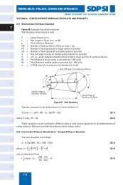
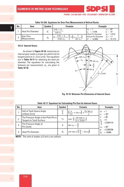
<strong>10</strong>.3.3 Internal Gears<br />
As shown in Figure <strong>10</strong>-<strong>10</strong>, measuring an<br />
internal gear needs a proper pin which has its<br />
tangent point at d + 2xm cir cle. The equations<br />
are in Table <strong>10</strong>-17 for obtaining the ideal pin<br />
diameter. The equations for calculating the<br />
between pin measurement, dm, are given in<br />
Table <strong>10</strong>-18.<br />
f<br />
tan ap<br />
ap<br />
inv ap<br />
ψ<br />
––<br />
2<br />
inv f<br />
Fig. <strong>10</strong>-<strong>10</strong> Between Pin Dimension of Internal Gears<br />
Table <strong>10</strong>-17 Equations for Calculating Pin Size for Internal Gears<br />
NOTE: The units of angles ψ/2 and f are radians.<br />
db<br />
d<br />
d + 2xm<br />
No. Item Symbol<br />
Formula<br />
Example<br />
1<br />
2<br />
3<br />
4<br />
Half of Tooth Space Angle<br />
at Base Circle<br />
The Pressure Angle at the Point Pin is<br />
Tangent to Tooth Surface<br />
The Pressure Angle at<br />
Pin Center<br />
Ideal Pin Diameter<br />
ψ –2<br />
ap<br />
f<br />
dp<br />
p 2x tan a<br />
(––– + inv a) + ––––––<br />
2z z<br />
zm cos a<br />
cos –1 [–––––––––]<br />
(z + 2x)m<br />
ψ<br />
tan ap – ––<br />
2<br />
ψ<br />
zm cos a (–– – inv f) 2<br />
m = 1<br />
a = 20°<br />
z = 40<br />
x = 0<br />
ψ<br />
–– = 0.054174<br />
2<br />
ap = 20°<br />
f = 0.309796<br />
dp = 1.6489<br />
dm