I R 1 2 3 4 5 6 7 8 9 10 11 12 13 T 14 15 A
I R 1 2 3 4 5 6 7 8 9 10 11 12 13 T 14 15 A
I R 1 2 3 4 5 6 7 8 9 10 11 12 13 T 14 15 A

You also want an ePaper? Increase the reach of your titles
YUMPU automatically turns print PDFs into web optimized ePapers that Google loves.
I<br />
R<br />
T<br />
1<br />
2<br />
3<br />
4<br />
5<br />
6<br />
7<br />
8<br />
9<br />
<strong>10</strong><br />
<strong>11</strong><br />
<strong>12</strong><br />
<strong>13</strong><br />
<strong>14</strong><br />
<strong>15</strong><br />
A<br />
ELEMENTS OF METRIC GEAR TECHNOLOGY<br />
T-98<br />
PHONE: 516.328.3300 • FAX: 516.326.8827 • WWW.SDP-SI.COM<br />
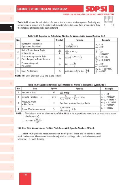
Table <strong>10</strong>-28 shows the calculation of a worm in the normal module system. Basically, the<br />
normal module system and the axial module system have the same form of equations. Only<br />
the notations of module make them different.<br />
Table <strong>10</strong>-28 Equation for Calculating Pin Size for Worms in the Normal System, (b)-3<br />
No. Item Symbol<br />
Formula<br />
Example<br />
1<br />
2<br />
3<br />
4<br />
5<br />
Number of Teeth of an<br />
Equivalent Spur Gear<br />
Half of Tooth Space Angle<br />
at Base Circle<br />
Pressure Angle at the Point<br />
Pin is Tangent to Tooth Surface<br />
Pressure Angle at<br />
Pin Center<br />
Ideal Pin Diameter<br />
NOTE: The units of angles ψv /2 and fv are radians.<br />
zv<br />
ψv<br />
–– 2<br />
av<br />
fv<br />
dp<br />
zw<br />
––––––––––<br />
cos 3 (90 – g )<br />
p<br />
––– – inv an<br />
2zv<br />
zv cos an<br />
cos –1 (–––––––)<br />
zv<br />
ψv<br />
tan av + ––<br />
2<br />
ψv<br />
zv mn cos an(inv fv + ––)<br />
2<br />
mn = 2.5<br />
an = 20°<br />
zw = 1<br />
d1 = 37<br />
g = 3.874288°<br />
zv = 3241.792<br />
ψv<br />
–– = – 0.0<strong>14</strong>420<br />
2<br />
av = 20°<br />
fv = 0.349550<br />
inv fv = 0.0<strong>14</strong>9687<br />
dp = 4.1785<br />
Table <strong>10</strong>-29 Equations for Three Wire Method for Worms in the Normal System, (b)-4<br />
No. Item Symbol<br />
Formula<br />
Example<br />
1<br />
2<br />
3<br />
4<br />
Actual Pin Size<br />
Involute Function f<br />
Pressure Angle<br />
at Pin Center<br />
Three Wire Measurement<br />
dp<br />
inv f<br />
f<br />
dm<br />
See NOTE 1<br />
dp p<br />
––––––––– – ––– + inv at<br />
mn zw cos an 2 zw<br />
Find from Involute Function Table<br />
zw mn cos at<br />
––––––––– + dp<br />
sin g cos f<br />
dp = 4.2<br />
at = 79.48331°<br />
inv at = 3.9995<strong>14</strong><br />
inv f = 4.216536<br />
f = 79.8947°<br />
dm = 42.6897<br />
NOTE: 1. The value of ideal pin diameter from Table <strong>10</strong>-28, or its approximate value, is to be used as the actual<br />
pin diameter, dp.<br />
tan an<br />
2. at = tan –1 (––––––)<br />
sin g<br />
<strong>10</strong>.4 Over Pins Measurements For Fine Pitch Gears With Specific Numbers Of Teeth<br />
Table <strong>10</strong>-30 presents measurements for metric gears. These are for standard ideal<br />
tooth thicknesses. Measurements can be adjusted accordingly to backlash allowance and<br />
tolerance; i.e., tooth thinning.<br />
Metric<br />
0 <strong>10</strong>