Defense structures in avalanche starting zones - SLF
Defense structures in avalanche starting zones - SLF
Defense structures in avalanche starting zones - SLF

Create successful ePaper yourself
Turn your PDF publications into a flip-book with our unique Google optimized e-Paper software.
3 > Plann<strong>in</strong>g of support<strong>in</strong>g <strong>structures</strong> 33<br />
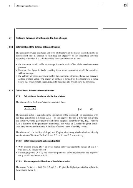
3.7 Distance between <strong>structures</strong> <strong>in</strong> the l<strong>in</strong>e of slope<br />
3.7.1 Determ<strong>in</strong>ation of the distance between <strong>structures</strong><br />
The distance between <strong>structures</strong> and rows of <strong>structures</strong> <strong>in</strong> the l<strong>in</strong>e of slope should be so<br />
dimensioned that <strong>in</strong> addition to fulfill<strong>in</strong>g the objective of the support<strong>in</strong>g structure<br />
accord<strong>in</strong>g to Section 3.2.1, the follow<strong>in</strong>g three conditions are all met:<br />
> the <strong>structures</strong> should suffer no damage from the static effect of the maximum snow<br />
pressure<br />
> likewise, the dynamic loads result<strong>in</strong>g from snow movement should be susta<strong>in</strong>ed<br />
without damage<br />
> the velocity of snow movement with<strong>in</strong> the support<strong>in</strong>g structure should not exceed a<br />
certa<strong>in</strong> limit<strong>in</strong>g value. The energy of motion is limited by the structure to a value<br />
below that which would cause damage to build<strong>in</strong>gs etc. ly<strong>in</strong>g below the structure.<br />
3.7.2 Calculation of distance between <strong>structures</strong><br />
3.7.2.1 Calculation of the distance <strong>in</strong> the l<strong>in</strong>e of slope<br />
The distance L <strong>in</strong> the l<strong>in</strong>e of slope is calculated from:<br />
L = fL<br />
⋅HK<br />
[m] (8)<br />
The distance factor fL depends on the <strong>in</strong>cl<strong>in</strong>ation of the slope and – <strong>in</strong> accordance with<br />
the three conditions <strong>in</strong> Section 3.7.1 – on the angle of friction ϕ between the ground<br />
and the snow, on the glide factor N and on the height of the structure HK. Fig. 13 shows<br />
fL as a function of the parameters mentioned. The value of fL under the given conditions<br />
may be obta<strong>in</strong>ed from the 3 families of curves tan ϕ, N and HK = const.<br />
The distances L (<strong>in</strong> the l<strong>in</strong>e of slope) and L' (plan view) may also be obta<strong>in</strong>ed directly<br />
as a function of DK from Tables 2.1 and 2.2, or 3.1 and 3.2, respectively.<br />
3.7.2.2 Safety requirements and ground surface<br />
> With smooth ground (N > 2) or for higher safety requirements, values of tan ϕ =<br />
0.55 and 0.50 should be used.<br />
> For rough ground (N < 2) and where no particular safety requirements are imposed,<br />
tan ϕ should be chosen as 0.60.<br />
3.7.2.3 Maximum permissible values of the distance factor<br />
The curves for tan ϕ = 0.60, N > 1.3 and fL = 13 give the highest permissible values for<br />
the distance factor fL.