Defense structures in avalanche starting zones - SLF
Defense structures in avalanche starting zones - SLF
Defense structures in avalanche starting zones - SLF

You also want an ePaper? Increase the reach of your titles
YUMPU automatically turns print PDFs into web optimized ePapers that Google loves.
04<br />
07<br />
> The environment <strong>in</strong> practice<br />
> Natural hazards<br />
> <strong>Defense</strong> <strong>structures</strong> <strong>in</strong><br />
<strong>avalanche</strong> start<strong>in</strong>g <strong>zones</strong><br />
Technical guidel<strong>in</strong>e as an aid to enforcement<br />
„“““““““““““““““““““““““““““““,^?0/›,,,““““““““,““““““,““,“,,,,,,,,“,“,,,,,,““,,,““““““““““““““““““““““““““““““,““““““““““““““““““““““<br />
„“““““““““““““““““““““““““““““^???/›,,,““““““““,““,,,,,“,,,,,,,,,,,,,“,,,,,,,,,,,,,“,,,“““,““““““““““““““““““““,,,“,““““““““““““““““““<br />
„“““““““““““““““““““““““““““^,^/??^›,,,“““““““,“,,,,,,,,,,,,,,,,,,,,,,,,,,,,,,“,,,,““,“““,“,““,““““““““““““““““,,,,,,,,,,“““““““““““““<br />
„““““““““““““““““““““““““““,,,“,??^›,,“,“,,,““,,,,,,,,,,,,,,,,,,,,,,,,,,,,,,,,,,,,,,,,,“,,,,“,“„,“““““““““““,““,,,,,,,,,,,,“““““““““““<br />
„““““““““““““““““““““““““,,,,““,&/›;,,“,,,,,,,,,,,,,,,,,,,,,,,,,,,,,,,,,,,,,,,,,,,,,,,,,,,,,,“,,““““,““““,“““,““,,“,,,,,,,,,““““““““““<br />
SNV<br />
„,““““““““,““““““““,,,,,,,,,,;,^0/›;,,““,,,,,,,,,,,,,,,,,,,,,,,,,,,,,,,,,,,,,,,,,,,,,,,,,,,,,,,,,““,,,,,,,,,“,“,“““““,,,,,,,““,“““““““<br />
„““,““““,““,,““,““,“,,,,,/,,;,“,,“““““,“,,,,,,,,,,,,,,,,,,,,,,,,,,,,,,,,,,,,,,,,,,,,,,,,,,,,,,,,,,,,,,,,,,,,,,“,“,“,,,,““,,,,““““,,“““<br />
„,,“““““““““““““““,,,,,,^^““;““;^^,,,“,,,,,,,,,,,,,,,,,,,,,,,,,,,,,,,,,,,,,,,,,,,,,,,,,,,,,,,,,,,,,,,,,,,,,,“,,,,,,,,,,,,“,,““,,,“,,““<br />
,““,““““,“““,,““,“““,,,,,,,“““›,,“,,,““,,,,,,,,,,,,,,,,,,,,,,,,,,,,,,,,,,,,,,,,,,,,,,,,,,,,,,,,,,,,,,,,,,,“,,,,“,,,,,,““,,,,,,,,,,,,,,<br />
%@%“““,“““,,““,,“““,““,,,,,““;,›^““““““,,,,,,,,,,,,,,,,,,,,,,,,,,,,,,,,,,,,,,,,,,,,,,,,,,,,,,,,,,,,,,,,,,,,,,,,,,,,,,,,,,,,,,,,,,,,,,,<br />
@@@@@?“““,“““,“““““““,““,,“,/,/››,“““““““,,,,,,,,,,,,,,,,,,,,,,,,,,,,,,,,,,,,,,,,,,,,,,,,,,,,,,,,,,,,,,,,,,,,,,,,,,,,,,,,,,,,,,,,,,,,,<br />
/%&@@0;,,““,,““,“““,,““,,“““^,?;“^“““,“;,,,,,,,,,,,,,,,,,,,,,,,,,,,,,,,,,,,,,,,,,,,,,,,,,,,,,,,,,,,,,,,,,,,,,,,,,,,,,,,,,,,,,,,,,,,,,,<br />
^/?00?&&/,,“““““““,,““,,;“/;;,,›,,;““,“›“,,,,,,,,,,,,,,,,,,,,,,,,,,,,,,,,,,,,,,,,,,,,,,,,,,,,,,,,,,,,,,,,,,,,,,,,,,,,,,,,,,,,,,,,,,,,,<br />
^›^^??@0&%@^^,““““““;,“,;,,;“0^,““;,,,,›““,,,,,,,,,,,,,,,,,,,,,,,,,,,,,,,,,,,,,,,,,,,,,,,,,,,,,,,,,,,,,,,,,,,,,,,,,,,,,,,,,,,,,,,,,,,,<br />
;,;,;“““&0?^,,“““,;;^›^@@0,^/?^^›,,›@^,;,,““,,,,,,,,,,,,,,,,,,,,,,,,,,,,,,,,,,,,,,,,,,,,,,,,,,,,,,,,,,,,,,,,,,,,,,,,,,,,,,,,,,,,,,,,,,<br />
,“,,,›››??%@%@%&&@@@@›;%&“,//?^›;,,^›@&^,,,,“,,,,,,,,,,,,,,,,,,,,,,,,,,,,,,,,,,,,,,,,,,,,,,,,,,,,,,,,,,,,,,,,,,,,,,,,,,,,,,,,,,,,,,,,,<br />
,,;,;;;›^^^0@%@@%%%@@%›,^“;^//^›;,,““^““;,“,^^^,,,,,,,,,,,,,,,,,,,,,,,,,,,,,,,,,,,,,,,,,,,,,,,,,,,,,,,,,,,,,,,,,,,,,,,,,,,,,,,,,,,,,,,<br />
,,,;;,;››››;/@%@@@@&&%/“^“^///^›,,,›,,›,^,;“,,““,,,,,,,,,,,,,,,,,,,,,,,,,,,,,,,,,,,,,,,,,,,,,,,,,,,,,,,,,,,,,,,,,,,,,,,,,,,,,,,,,,,,,,<br />
,;›,;›;;;;;,^&?%@%@&^//,,›^/?/^›,,,,;›;;^;›;;“,,,,;“,,,,,,,,,,,,,,,,,,,,,,,,,,,,,,,,,,,,,,,,,,,,,,,,,,,,,,,,,,,,,,,,,,,,,,,,,,,,,,,,,,<br />
,››,;;;›››,“^^???%?@%^^;››;/?^›;,,,››››;›/››,;,,,,,,“,,,,,,,,,,,,,,,,,,,,,,,,,,,,,,,,,,,,,,,,,,,,,,,,,,,,,,,,,,,,,,,,,,,,,,,,,,,,,,,,,<br />
››››;;››››^^/^^^/&&%%%?;››/,,^›;,,,;›^^^^/^^››››,,,,,,“,,,,,,,,,,,,,,,,,,,,,,,,,,,,,,,,,,,,,,,,,,,,,,,,,,,,,,,,,,,,,,,,,,,,,,,,,,,,,,,<br />
;›››;;›››^?/^?^^//?%@@@@%›^//››;,,››^^^/›@^;^›^^›;^0,“,,“,,,,,,,,,,,,,,,,,,,,,,,,,,,,,,,,,,,,,,,,,,,,,,,,,,,,,,,,,,,,,,,,,,,,,,,,,,,,,<br />
››››^›››^///??^^^/?0?&@%%?^/^^›,,,;›^^^^›%››^›››^^›^;/??,,,“,,,,,,,,,,,,,,,,,,,,,,,,,,,,,,,,,,,,,,,,,,,,,,,,,,,,,,,,,,,,,,,,,,,,,,,,,,<br />
^^^^^››^^/^/00/^0^^/0&@@0/^^^^;,,›^^^^^››,›^^^^;;,,“““/0&%,,,“,,,,,,,,,,,,,,,,,,,,,,,,,,,,,,,,,,,,,,,,,,,,,,,,,,,,,,,,,,,,,,,,,,,,,,,,<br />
^›^^^›^^^/^//??///^/?0&%0^^^^›;,,,“;›^“›^›;››^^›^^^^^^/&&%%^&,,,“,,,,,,,,,,,,,,,,,,,,,,,,,,,,,,,,,,,,,,,,,,,,,,,,,,,,,,,,,,,,,,,,,,,,,<br />
^/^^^^^^^^^/^›^/^^/›^??//,^/^›;,,;››^››^^^››^^^^^//^&?,%%@@&0,,,,,,,,,,,,,,,,,,,,,,,,,,,,,,,,,,,,,,,,,,,,,,^›,^;,,,,,,,,,,;;;,;;;;;;;;<br />
^^^^///////^^^^^^^^››//?/›,›^›,,,››^^^^›››^›^›^^^/^/0/›@@@@%&@^@%,“,,,,,,,,,,,,,,,,,,,,,,,,,,,,,,,,,,,,,,,›^%?^;,,,,,;;;;;;;;;;;;;;;;;<br />
^/////////^^^^^^^^^^›^^/?,,,›;,,›?^›^^^^^^^;››^/^//^&?^&%%%%?%0›&/@%,,,,,,,,,,,,,,,,,,,,,,,,,,,,,,,,,,,,,;›^“^›,;,;;;;;;;;;;;;;;;;;;;;<br />
/////^///^^^^^^^^^^^^›/›“,,,,,,;^^^^^^^^^^^›,›//?0/???0/%@%&?%0/^0&@@@&,,@^@,›,,,,,,,,,,,,,,,,,,,,,,,,;,,“,;“,;,;;;;;;;;;;;;;;;;;;;;;;<br />
^^//^//^^^^^^^^^^^^^›››““,,,,,,,›^?^^^^/^^/^,/^??%^??0@0&%&&0??0;&@%@@@@@^@%@0,,“,;,,,,,,,,,;;,;;;;;;;;;;›“›“““,;;;;;;;;;;;;;;;;;;;;;;<br />
//^//^^^^^^^/^^›^›^›››;““,,,,,,;›^?^^›^/////›?^?&&/?0@@%^%/&&?/?0%@@@@@@@&@@%@%,,,,“›››;;;;,;;;;;;;;;;;;,“/^›,“;;;?;;;;;;;;;;;;;;;;;;;<br />
^^///^^^////^^;›^^^››››“,,,,,,,››^^^^^^^////&??›0&?0%%@@@@@%&????^@@@%@@@%@@@@%;,,,;;;;,;;,“““,;;;;;;,,,““,“,,,;;›;;;››››;;;;;;;;;;;;;<br />
^/^^^^^^/^^^›^›^^^^^›››“,,,,,,,››^^^^^›^////0???/0?%%&%&%&&0%0??&%%@@@@%&%0%%%0;;;,;,;;;;;;“;;;;;;;;“,“,››&/,“››;;›››››››;;;;;;;;;;;;;<br />
//^^^^/^^^››^^^››››^›^›“,,,,,,,^^››^^^^^^///?//?›?0%&0&?%^000??0%@%@%&%@%%/&@@&/,;›;,,›;;;,;;;›;››;›,;,;^/&^,,;›››,›››››;;;;;;;;;;;;;;<br />
/^^^^/^^›››››^›››››››^,“,,,,,,;^^^^^^^^^^//////?/›&&@&&0&,0/????&&%@%&&&00/?%@%&››;;,›;››››››››››“;;;;,;^?/;,;›››››%››››;;;;;;;;;;;;;;<br />
^^^///^;›››^;›››››^›››““,,,,,,^^^››^^^^^//////???›?000?&?^^?????%%&@&000?0/?&%&/^;;,;›››››››››;››;›,,;›;^^?,,›››››››,››^›;;;;›;;;;;;;;<br />
^^///›››››››^›››^^^›››“,,,,,,,^,“,›^^^^////?////??›????00&›///??00%0?????/?/@%&^›/&››,››››;››››,;›,,,›;››0/;,;›;;›,››;@;›››››;;;;;;;;;<br />
///^›››^›^^^^^^^^›^^›;“,,,,,,,^^^^›^^^^^^///////??/?0000?/;^//???0&00???0?0?%0&/^^&&%?%&››››››;;››“,^^››0?;›››;;›;;;,;,›;›››;;;;;;;;;;<br />
^/^^›››^^^^^^^^^^^^^›,,,,,,,,,^^^^^›^^^///////^^???›????^/“^//??000&00???0%@&%0^0›^%%%&&^››››;;;›,,^^^››/;,;›^,;›;›;;&,;››››;;››;;;;;;<br />
^^››^^^^^^^^^^^^^^^›^““,,,,,,;^^^^^›^^^^^//^///^///^^??/?/,//??000&000&&@&@%^??//;^?&&/%?^›;“››;,,^^^›;^?›^;^›››››;,;,›;››››››››;;;;;;<br />
›››››^^^^^^›››^^^›››^“““;,,,“›^^^^^›^^^^/////////??/›?????^^???00&&&0&&%&&0&/////›^%%@›@%@@@^^›,,;^›^;›^?,››^››››;,;/,;›;;,;››››››››››<br />
››››^^^^^^^›^^^^^›^^›““,,,,,,^^›^›^››^^//////??/›/???›?????;&0000&@@%000000?^////;››^?@^0&??›^^›,^›^››^›;^;››››;;;;;^›››;›,,››››››››››<br />
››^››^^›^^^›^^^^^^^^,“,,,,,,,››;“›^›››^//////??/^/???^????/“?&%@@%@&&?000?00/???^^›^›^%,%@@@@@,,^^››››^?››;›››;›››››,››››,;,;^››^›››››<br />
›››^›^^^^^››^^^›^^^^““,,,;,,;^››^^^^››^/////////^^????›????;???&00%???000??/??///^,^/?%&%%&@%^;›››,;››››^›,›;›››››;/›^›;;›;››^^^^^^^^^<br />
›››^^^^››››››^››^››^““,,,;,,›››^›^^^›^›^^^^/^^///›//?/›^///^//????0??0000?00?///^^^/?&&&???&,%?@,^““›;/;›;,›;›››››?,^^,;›/››››^/^^^^^^<br />
^›^››››››››^^^^›^^^^““,,,,,,›››^^^^^^^^^^^///////^//???›??///???????//???0000?//^^^^/0%@/??/?/^0&0;,›/,/›,››;^^^››?›››;;›;^^^^/,;^^^^^<br />
››››››››››^^^^^››^^^““,,,,,;››^^^^^›^^^^^^//////?//////?›?//??00????//???????//?/?/;^0//////?/%0&??››^›^;;0;^^^^^›;›^;^›^›^^›,›››,›^^^<br />
›››››››^^^›^^^^››^^,““,,;,,›;›››››^^^›^^//////?/??›////?›/???????????/?/?????????//,^/???^^?@@@%^;&;^,0^;›,^^^^^›^››;^^››^^^,;›››^,/^^<br />
››››››››^^››^^››››^““,,,;,,^^,›^›››››^^^^^///^^^^^^^/??//›///????0??????????/???///?^/?//^//&000&0&››^^›,;^^›^,›^;›;^^›^›^;,››››;››,^^<br />
,,;›;›;››››››››››^›“““,,,,,^^“^;›››^^^^^^//////////;////??//^???????//???0&&&????/??/?^^/////&%?//;›^^^›^?/;?/^^/;,^^››?^;;^›^;;›;›^^^<br />
,“,;;,“,,;››››››^››““,,,,,,^^;››^^^^^^^^///////////,/?????›//?00000??/???00&&???????^^^^/^^/0&?0%?›^,/›;?&%00&0,;^^^››››^;^^^;››;;;;›^<br />
,,,,,“,,;;››››››››,““,,,,,›^›››^^^^^^^^///^//////?^^///???/›//??0????????00??/?????^^^^^/^^/%@@@&/^;/^›,@&0/?&&?,&&/^›/››^›;/››^›^,›››<br />
„,“,,,,,;;›››››››;“““,,;,;^^›››^^^^^^///^/,///^^////›//////›/?0/?%&?????/???//???^^^^^^^^/^@%%%%@^^›?^›^&&&/?&›,00?^&^^,&^›^››››;›^?^^<br />
„,““,,,,,;›››››››;““,,,,,,›^››››^^/^/^^^^^›^//^/////›//////?›,//??????//////?^^^^^^^^^›^/^&&@@%%%;›^/›;@@%&^0&›?0%?/&/;&›?/^››^››^›^^^<br />
„,“““,,,,;;››››››,“““,,,,,;›^›;››^/^^^^^^/^^^^^^////^////???/^^//?????/?0^^^^^^^^^^^^^^^^%%&&&&%?,,?^›;?››››››;;;›0%&^&&?0&;›;›^^^^^^^<br />
„,,,“,,,,;››››››;“““,,,,,,,;››^^^^^^›^^^//^›^^^//////›///////››//?/?/›››^›››^›^›^^^^^^^^@&&&&&&&,,›^^;›?&@@%&&%%&^%%@?/^/&^&0›^›;›;^^^<br />
,,“,,,;,;;››››››,““““,,,;,›^^›^^^^^^;›^^^^^^›^^^^////;^^^^///^›^/??›››››››^^^››^^^›^^›^@@@@@&&&%,,^/›,@@@%@@%%%%%%%%%%%&%^%%0/&/^?^^^^<br />
,,“““;;;,;;››››;,“““,,,,,;›^›^^^^^^^,;››^^^^›^^^^^/^^;›^^^^^^^;;“›;;;››,,››››››^^^^^›@@@@@@@@@%›,,;^›/&&&@@@@@@%%%%%%%&%%&&&%%/%@%&^^^<br />
„,“““;;;,;››››;;““““,,,,,››››››^^^^^^;›››^^^›,››^›;;,,“,,;›,,›;›^“,;››,;;››››;››››^››^%@@@@@@@@,,;;^›%&&&&&&@@@%@%%@@%%%%%%%&%%/&0%%&&<br />
„““““,;;;;›››››;““““,,,,,;›››^^^^^^^^^›››^^^^›;“““,“““““““““,,›››››,››››;,›››››››››;;››^%@@@@@@,,,,^;&&&&&&&&&@%%%%@@%%%%@%%%%&&0&%%&&<br />
„“““““;;;››››^^^››““,,,,,;›››››^^^^^^^^›^^^^^^›;“““““““““,,,,;^››››››››““››››,››,,,,;››››››^@@/,,;^››@&%&&&&&&&&&%%@&&%%%&%@%%&%&&&0&0<br />
„“““,,;;››››^^^››^;““““““;›^››^›^^^^^^^^^^^^^^^›“,“““,““,“,,;›^›››››^^›››››››,;;““,,;;››››››››,,,^››@@@@@%%&&&&&&&&&&%&%%%%&%%@%&/&00&<br />
„“““,;››;››››››››››““““““,›^^››››^^^^^^^^^^^^^^^›““,,,“““,;›^^^^^›^››^^››››››››››››;;;››››››››,,;^›;0@@@@@@@%&&&&&&&&&&%&%&%%&%%&&?&00<br />
„“,,,;;›››››››››››››“““““,;›››^››^^^^^^^^^^^^^^^^;“““,““,;^^^^^^^^›^^›^^›››^^^›››››;;›››››››;“,,;^››^@@&@@@@@@@%&&&&&&&&&%&0&&&&%%&&&0<br />
,,,;;››››››››››››››››;“““,,››››^›^^›^^^^^^^^^^^^^^^››“››››^^^^^^^^›^^^^^^››››^^^^›››››^^^^›››“,,;^;›››&/%&00/0&0^0^›/&&&&&&0&?&&&&0?&&<br />
;›››››››››››››››››››“,››“,,;›››^›^^^^^›^^^^^^^^^^^^^^››››^^^^^^^^^^›^^^^^^›››››^^^^^^›››^^^›,,,;;›;0?^›0&?0?00&??^››››^&&&&&000?00&0&&<br />
››››››››››››››››››››››››››,,;;›^›››^›^^^^^^^^›^^^^^^^^^^^^^^^^^^^^/››^^^^^^››››››^^^^^›››››;“,,^^›;0&@&&&%@%%%??^›^^^??@%%&&&&000?00&0<br />
››››››››››››››››››››››››››;;;;››››^^^›^^^^^^^^^^^^^^^^^^^^^^^^^^^?%%›^^^^^^^›^››››››^››››››;“,,^››;;;0%%&&&%?^^›››^/@@@%%&&%%&&&000?0?<br />
››››››››››››››››››››››››^›,,;›››››^››^^^^^^^^^^^^^^^^^^^^^^^^^^^/?%%^›^^^^^^››››››››››››^›››“,;››››;››››&&&››››^^^%%%@@@@%@%&%%%&&0000<br />
›››››››››››››››››››››››››››››››››››^››^^^^^^^^^^^^^^^^^^^^^^^^^/0%%@%›&/&^^^^››››››››^›››^›››,;›››››^%››››››››››^@@%@&%@@@%@@@&&@%&&&0<br />
›››››››››››››››››››››››››››››››››››››››››^^^^^^^^^^^^^^^^^^^^^^/&%@@@@^@&/^^0^^›››››››^^^^^›^^›;›››^/@%?%@&%&&/0%0@@@%@%&%@%@@@@@&&&%&<br />
›››››››››››››››››››››››››››››››››››››››››››^^^^^^^^^^^^^^^^^^^//%@@@@@›&@%%&%@0&&&››››››^^^^^/%^›^@@@@@@@%%@%%&&&%%%%@%%@@%%@@@@@@@%&&<br />
››››››››››››››››››››››››››››››››››››››››^›››^^^^^^^^^^^^^^^^^?0%@@@@@@@›@@%&&%@%/%@@&^››^^?%%&%@@@%@@@@@%%@@%&&%&%&&%@%%%&%%@%%@@@@@@@<br />
›››››;›››››››››››››››››››››››››››››››››^/››››^^^^^^^^^^^^^^^?@@@@@@@@@@%/@^%@@&%?@%%@@%%%&%@@@%%@@@%@@@@@@@@@@%%@&%@&00%@%&@%&@%?@@@@@<br />
››;›››;››››››››››››››››››››››››››››››^^&^^^^^^//^//^^^^^^??&%@%@@@@@@@@@›@@%%%&&&0@@@%@@@%&%@@@%%%@@@@@@@@@%%@%%&&@%%@&&00@@%%&&%&&&@@<br />
<strong>SLF</strong><br />
ENA<br />
SNV<br />
PNL<br />
WSL<br />
Swiss Federal<br />
Institute for Snow<br />
and Avalanche<br />
Research <strong>SLF</strong>
The environment <strong>in</strong> practice > Natural hazards<br />
> <strong>Defense</strong> <strong>structures</strong> <strong>in</strong><br />
<strong>avalanche</strong> start<strong>in</strong>g <strong>zones</strong><br />
Technical guidel<strong>in</strong>e as an aid to enforcement<br />
Editors:<br />
Federal Office for the Environment FOEN<br />
WSL Swiss Federal Institute for Snow and Avalanche Research <strong>SLF</strong><br />
Bern, 2007
Legal status of this publication<br />
This publication is an implementation guide issued by FOEN <strong>in</strong> its capacity<br />
as a supervisory authority, and is addressed primarily to the enforcement<br />
authorities. It seeks to clarify undef<strong>in</strong>ed legal concepts conta<strong>in</strong>ed<br />
<strong>in</strong> the relevant Acts and ord<strong>in</strong>ances so as to facilitate consistent<br />
enforcement practices. Authorities who give due consideration to these<br />
guides can safely assume that federal law is be<strong>in</strong>g correctly implemented.<br />
Alternative approaches are, however, permissible provided they comply<br />
with the legal requirements. Guides of this k<strong>in</strong>d (until now also referred to<br />
as guidel<strong>in</strong>es, guidance, recommendations, handbooks, enforcement aids,<br />
etc.) are published by FOEN <strong>in</strong> the series entitled “Environment <strong>in</strong><br />
Practice”.<br />
Impressum<br />
Published by<br />
Federal Office for the Environment (FOEN)<br />
The FOEN is an office of the Federal Department of Environment,<br />
Transport, Energy and Communications (DETEC).<br />
WSL Swiss Federal Institute for Snow and Avalanche Research <strong>SLF</strong><br />
Revis<strong>in</strong>g Author<br />
Stefan Margreth, Research Unit Warn<strong>in</strong>g and Prevention,<br />
WSL Swiss Federal Institute for Snow and Avalanche Research <strong>SLF</strong>, Davos<br />
Supervision FOEN<br />
Reto Baumann, Department of Risk Prevention, FOEN<br />
Suvervision EKLS<br />
R. Baumann, President of the Expert Commission for Avalanches and<br />
Rockfall (EKLS), Department of Risk Prevention, FOEN<br />
J. Marx, Department of Forestry and Hunt<strong>in</strong>g of the Canton of Uri<br />
H. Buri, Head of the Department of Natural Hazards of the Canton of Bern<br />
<strong>SLF</strong> scientific team<br />
S. Margreth (Project Leader), F. Leuenberger, T. Lundström, M. Auer,<br />
R. Meister<br />
Review<strong>in</strong>g<br />
Dr. W. Ammann, Deputy Director WSL; A. Böll, WSL;<br />
R. Rüegger, Eng<strong>in</strong>eer<strong>in</strong>g Consultant<br />
Suggested form of citation<br />
Margreth, S., 2007: <strong>Defense</strong> <strong>structures</strong> <strong>in</strong> <strong>avalanche</strong> start<strong>in</strong>g <strong>zones</strong>.<br />
Technical guidel<strong>in</strong>e as an aid to enforcement. Environment <strong>in</strong> Practice<br />
no. 0704. Federal Office for the Environment, Bern; WSL Swiss Federal<br />
Institute for Snow and Avalanche Research <strong>SLF</strong>, Davos. 134 pp.<br />
Translation<br />
en-solar, Heimenschwand<br />
Layout<br />
Ursula Nöthiger-Koch, Uerkheim<br />
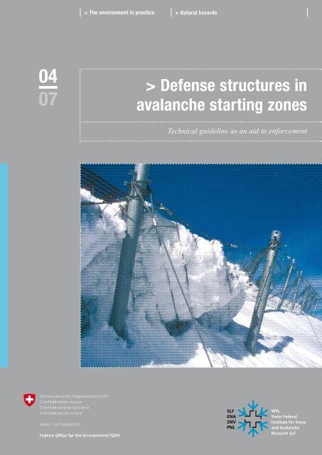
Cover picture<br />
Snow net <strong>in</strong> the Duchli defense area above Davos (2001),<br />
<strong>SLF</strong>, S. Margreth<br />
Orders<br />
FOEN<br />
Documentation<br />
CH-3003 Bern<br />
Fax +41 (0)31 324 02 16<br />
docu@bafu.adm<strong>in</strong>.ch<br />
www.environment-switzerland.ch/uv-0704-e<br />
Order Number:<br />
UV-0704-E<br />
This publication is also obta<strong>in</strong>able <strong>in</strong> German, French and Italian<br />
(UV-0704-D, UV-0704-F, UV-0704-I).<br />
© FOEN / WSL 2007
Table of contents 3<br />
> Table of contents<br />
Abstracts 5<br />
Foreword 7<br />
Purpose and legal basis of the technical guidel<strong>in</strong>e 9<br />
1 Scope 11<br />
1.1 Delimitation 11<br />
1.2 Relationship to the SIA standards 11<br />
1.3 Other protective measures 12<br />
2 Nomenclature 13<br />
2.1 Organizations 13<br />
2.2 Technical Terms 13<br />
2.3 Units and comments on term<strong>in</strong>ology 16<br />
2.4 Symbols 16<br />
3 Plann<strong>in</strong>g of support<strong>in</strong>g <strong>structures</strong> 19<br />
3.1 Avalanche formation mechanisms 19<br />
3.2 Purpose and function of support<strong>in</strong>g <strong>structures</strong> 21<br />
3.3 Structure types 22<br />
3.4 Extent and position<strong>in</strong>g of a support<strong>in</strong>g structure 23<br />
3.5 Snow height 28<br />
3.6 Height of structure 32<br />
3.7 Distance between <strong>structures</strong> <strong>in</strong> the l<strong>in</strong>e of slope 33<br />
3.8 Lateral distance between <strong>structures</strong> 40<br />
3.9 Lengths of cont<strong>in</strong>uous support grates 41<br />
3.10 Site factors for snow pressure 42<br />
3.11 Foundation conditions 44<br />
4 Overview of snow pressure effects 45<br />
4.1 General 45<br />
4.2 Pressure component <strong>in</strong> the l<strong>in</strong>e of slope 45<br />
4.3 Pressure component normal to the slope 46<br />
4.4 Increment for non-normal support<strong>in</strong>g surface 47<br />
4.5 End-effect forces 48<br />
4.6 Snow pressure on slender elements of a<br />
support<strong>in</strong>g structure 49<br />
4.7 Lateral loads 50<br />
5 Dimension<strong>in</strong>g of separated support<strong>in</strong>g<br />
<strong>structures</strong> 51<br />
5.1 Materials 51<br />
5.2 Structural analysis and dimension<strong>in</strong>g 53<br />
5.3 Structural design, detail<strong>in</strong>g 58<br />
5.4 Execution and ma<strong>in</strong>tenance 58<br />
5.5 Loads on the structural system 60<br />
5.6 Loads on the grate 67<br />
5.7 Dimension<strong>in</strong>g and execution of the structural<br />
system 69<br />
5.8 Dimension<strong>in</strong>g and execution of the grate 72<br />
5.9 Execution and dimension<strong>in</strong>g of the foundations 77<br />
6 Use of anchor grout <strong>in</strong> <strong>avalanche</strong> defense 99<br />
6.1 General 99<br />
6.2 Normal anchor grout 100<br />
6.3 Special anchor grout for use <strong>in</strong> permafrost 103<br />
7 Avalanche defense <strong>in</strong> permafrost 105<br />
7.1 General 105<br />
7.2 Inspection of the ground 108<br />
7.3 Assessment of creep probability <strong>in</strong> the ground 113<br />
7.4 <strong>Defense</strong> <strong>structures</strong> <strong>in</strong> permafrost 115<br />
7.5 Anchor<strong>in</strong>g <strong>in</strong> permafrost (loose soil or bedrock) 119<br />
7.6 Use of grout <strong>in</strong> permafrost 122<br />
7.7 Ma<strong>in</strong>tenance 123<br />
7.8 Flow diagram: plann<strong>in</strong>g procedure 124<br />
8 Type approval 125<br />
8.1 Purpose 125<br />
8.2 Test objects 125<br />
8.3 Adm<strong>in</strong>istrative procedure 126<br />
8.4 Requirements 127<br />
8.5 Inspections 127<br />
8.6 Required documentation 129<br />
8.7 Costs of <strong>in</strong>spection 131<br />
8.8 Validity of the test 131<br />
8.9 Type approval list 131<br />
8.10 Confidentiality and disclosure to third parties 131
Technical Guidel<strong>in</strong>e for <strong>Defense</strong> Structures <strong>in</strong> Avalanche Start<strong>in</strong>g Zones FOEN / WSL 2007 4<br />
Index 133<br />
Figures 133<br />
Tables 134
Abstracts 5<br />
> Abstracts<br />
The technical guidel<strong>in</strong>e regulates the plann<strong>in</strong>g of snow support<strong>in</strong>g <strong>structures</strong> and the<br />
dimension<strong>in</strong>g of separated <strong>structures</strong>. The procedures and criteria for type approval,<br />
together with the requirements for support<strong>in</strong>g <strong>structures</strong> and anchor grout are specified.<br />
Further, an overview of the effects of snow pressure and <strong>in</strong>structions on the plann<strong>in</strong>g of<br />
defense <strong>structures</strong> <strong>in</strong> permafrost are given. The guidel<strong>in</strong>e draws heavily on past experience<br />
ga<strong>in</strong>ed with support<strong>in</strong>g <strong>structures</strong>, and is complementary to the relevant SIA<br />
standards. It is directed towards designers and project eng<strong>in</strong>eers.<br />
Die vorliegende technische Richtl<strong>in</strong>ie regelt die Projektierung von Stützverbauungen<br />
und die Bemessung von gegliederten Stützwerken. Der Ablauf der Typenprüfung und<br />
die Prüfkriterien sowie Anforderungen an Stützwerke und Ankermörtel werden festgelegt.<br />
Weiter wird e<strong>in</strong>e allgeme<strong>in</strong>e Übersicht über die Schneedruckwirkung gegeben<br />
sowie Angaben gemacht, wie Law<strong>in</strong>enverbauungen im Permafrost zu planen s<strong>in</strong>d. Die<br />
technische Richtl<strong>in</strong>ie stützt sich stark auf die <strong>in</strong> der Vergangenheit im Stützverbau<br />
gemachten Erfahrungen ab und ergänzt die e<strong>in</strong>schlägigen SIA-Normen. Sie richtet sich<br />
an Konstrukteure und Projektverfasser.<br />
La présente directive réglemente l’élaboration du projet de construction de par<strong>avalanche</strong>s<br />
et le dimensionnement des ouvrages de stabilisation composés. Elle déf<strong>in</strong>it le<br />
déroulement de l’examen des types d’ouvrages, les critères du test a<strong>in</strong>si que les exigences<br />
liées aux ouvrages de protection et aux mortiers d’ancrage. Un aperçu général des<br />
effets de la pression de la neige et des <strong>in</strong>dications sur la planification des par<strong>avalanche</strong>s<br />
dans le pergélisol y sont également présentés. Largement <strong>in</strong>spirée de l’expérience<br />
acquise, cette directive complète les normes SIA en vigueur. Elle s’adresse aux constructeurs<br />
et aux auteurs de projets.<br />
Questa direttiva tecnica discipl<strong>in</strong>a la progettazione delle opere di premunizione e il<br />
dimensionamento di opere di sostegno strutturate, stabilisce lo svolgimento dell’omologazione<br />
dei tipi di strutture e i criteri di esame e fissa i requisiti posti per le opere di<br />
sostegno e la malta di ancoraggio. Inoltre, fornisce una panoramica generale della<br />
pressione esercitata dalla neve sulle opere di sostegno e <strong>in</strong>dica come pianificare le<br />
opere di premunizione contro le valanghe nel permafrost. La direttiva poggia <strong>in</strong> gran<br />
parte sulle esperienze acquisite <strong>in</strong> passato nell’ambito delle opere di premunizione e<br />
<strong>in</strong>tegra le vigenti norme SIA. Si rivolge a costruttori e progettisti.<br />
Keywords:<br />
<strong>Defense</strong> <strong>structures</strong>,<br />
<strong>avalanche</strong> protection,<br />
type approval,<br />
guidel<strong>in</strong>e,<br />
permafrost<br />
Stichwörter:<br />
Stützverbau,<br />
Law<strong>in</strong>enschutz,<br />
Typenprüfung,<br />
Richtl<strong>in</strong>ie,<br />
Permafrost<br />
Mots-clés :<br />
Ouvrage de stabilisation,<br />
protection contre les <strong>avalanche</strong>s,<br />
examen des types d’ouvrages,<br />
directive,<br />
pergélisol<br />
Parole chiave:<br />
opere di premunizione,<br />
protezione contro le valanghe,<br />
omologazione dei tipi di strutture,<br />
direttiva,<br />
permafrost
Foreword 7<br />
> Foreword<br />
Alongside protective forest – a biological protective measure – support<strong>in</strong>g <strong>structures</strong><br />
represent the primary form of protection from <strong>avalanche</strong>s <strong>in</strong> Switzerland. Technical<br />
and biological protective measures are often comb<strong>in</strong>ed. Today, over 500 km of permanent<br />
support<strong>in</strong>g <strong>structures</strong> are <strong>in</strong> service. In addition, about 150 km of temporary<br />
support<strong>in</strong>g <strong>structures</strong> are <strong>in</strong> use <strong>in</strong> comb<strong>in</strong>ation with reforestation measures. The modern<br />
support<strong>in</strong>g <strong>structures</strong> withstood the severe test <strong>in</strong> the <strong>avalanche</strong> w<strong>in</strong>ter of 1999,<br />
dur<strong>in</strong>g which numerous <strong>avalanche</strong>s hav<strong>in</strong>g high damage potential could be prevented.<br />
In Switzerland, the most important support<strong>in</strong>g <strong>structures</strong> have now been realized, so<br />
that the pr<strong>in</strong>cipal challenge for the future will be the ma<strong>in</strong>tenance of exist<strong>in</strong>g works.<br />
Present-day support<strong>in</strong>g <strong>structures</strong>, which started life as terrace walls, to be followed by<br />
concrete and alum<strong>in</strong>um support<strong>in</strong>g <strong>structures</strong>, and f<strong>in</strong>ally by modern snow bridges<br />
fastened to anchors and micropiles, requir<strong>in</strong>g a long period of development. Current<br />
build<strong>in</strong>g materials together with new research knowledge and experience all reflect the<br />
cont<strong>in</strong>ually chang<strong>in</strong>g status of technology. Work on the technical guidel<strong>in</strong>e, a recognized<br />
work both at home and abroad, began <strong>in</strong> the 1950s by Dr. Bruno Salm and was<br />
later <strong>in</strong>fluenced substantially by the work of Stefan Margreth of the Federal Institute<br />
for Snow and Avalanche Research (<strong>SLF</strong>) <strong>in</strong> collaboration with the Federal Laboratories<br />
for Materials Test<strong>in</strong>g and Research (EMPA) and specialists from the Expert Commission<br />
for Avalanches and Rockfall (EKLS). The present updated version of the technical<br />
guidel<strong>in</strong>e is the product of over 50 years' development. The previous edition of 1990<br />
was extended to <strong>in</strong>clude the latest SIA structural codes, the layout has been revised,<br />
knowledge result<strong>in</strong>g from the <strong>avalanche</strong> w<strong>in</strong>ter of 1999 <strong>in</strong>cluded, and the chapters on<br />
type approval tests and the use of anchor grout <strong>in</strong> support<strong>in</strong>g <strong>structures</strong> added.<br />
When apply<strong>in</strong>g for federal subsidies for <strong>avalanche</strong> support<strong>in</strong>g <strong>structures</strong> accord<strong>in</strong>g to<br />
art. 36 WaG (Law on Forests), officially tested and approved types of structure and<br />
anchor grout must be implemented. The requirements for this are specified <strong>in</strong> the<br />
present guidel<strong>in</strong>e. The Federal Office for the Environment ma<strong>in</strong>ta<strong>in</strong>s a list of approved<br />
types of structure and anchor grout.<br />
The effect of snow pressure on support<strong>in</strong>g <strong>structures</strong> is complex. To permit simple<br />
implementation of the guidel<strong>in</strong>e by eng<strong>in</strong>eers, loads and analytical load models have<br />
been heavily simplified. Note, however, that <strong>in</strong> practical cases other loads and load<br />
cases may occur that are not covered by the present guidel<strong>in</strong>e. Those us<strong>in</strong>g the technical<br />
guidel<strong>in</strong>e must always rema<strong>in</strong> aware of this fact, which makes a correspond<strong>in</strong>g high<br />
level of competence on their part essential.<br />
Andreas Götz Dr. Walter J. Ammann<br />
Deputy Director Deputy Director<br />
Swiss Federal Office Swiss Federal Institute for Forest,<br />
for the Environment (FOEN) Snow and Landscape Research (WSL)
Purpose and legal basis of the technical guidel<strong>in</strong>e 9<br />
> Purpose and legal basis<br />
of the technical guidel<strong>in</strong>e<br />
The present technical guidel<strong>in</strong>e for defense <strong>structures</strong> <strong>in</strong> <strong>avalanche</strong> start<strong>in</strong>g <strong>zones</strong> issues<br />
from the Federal Law on Forests (WaG, SR 921.0) of 4 October 1991, which specifies<br />
the general and specific conditions for the grant<strong>in</strong>g of federal subsidies for measures<br />
for the protection of humans and material assets from natural hazards (arts. 35 and 36<br />
WaG). The Ord<strong>in</strong>ance relat<strong>in</strong>g to Forest (WaV; SR 921.01) of 30 November 1992<br />
specifies particular conditions for the grant<strong>in</strong>g of federal subsidies, and also covers the<br />
competency of the FOEN to issue guidel<strong>in</strong>es <strong>in</strong> this field (art. 39, para. 3 WaV). Where<br />
applications are made for federal subsidies for <strong>avalanche</strong> defense <strong>structures</strong> under art.<br />
36 WaG, these must basically implement officially tested and approved types of structure<br />
and anchor grout. The present technical guidel<strong>in</strong>e specifies the relevant requirements.<br />
The follow<strong>in</strong>g objectives are thereby pursued:<br />
> Advice to those responsible for the plann<strong>in</strong>g, build<strong>in</strong>g and ma<strong>in</strong>tenance of support<strong>in</strong>g<br />
<strong>structures</strong><br />
> Overview of snow pressure effects<br />
> Procedure for dimension<strong>in</strong>g separated support<strong>in</strong>g <strong>structures</strong><br />
> Specification of the requirements for anchor grout<br />
> Specification of requirements for <strong>avalanche</strong> defense <strong>structures</strong> <strong>in</strong> permafrost<br />
> Specification of procedures for type approval tests<br />
Avalanche support<strong>in</strong>g <strong>structures</strong> are mostly erected at high altitudes on highly <strong>in</strong>accessible<br />
slopes hav<strong>in</strong>g a variety of different ground characteristics. Simple, <strong>in</strong>expensive,<br />
robust and well-proven structural methods are therefore essential for successful, durable,<br />
implementation of <strong>avalanche</strong> defense <strong>structures</strong>. The technical guidel<strong>in</strong>e draws<br />
heavily on the experience obta<strong>in</strong>ed <strong>in</strong> the past with support<strong>in</strong>g <strong>structures</strong>. For this<br />
reason, differences have arisen from SIA 267 Geotechnology, particularly <strong>in</strong> connection<br />
with the dimension<strong>in</strong>g of foundations and anchors.<br />
The effects of snow pressure on support<strong>in</strong>g <strong>structures</strong> are very varied. Often, situations<br />
occur that are not well understood, and it is not always possible to clarify these despite<br />
careful observation and measurement. The <strong>in</strong>formation conta<strong>in</strong>ed <strong>in</strong> this guidel<strong>in</strong>e is<br />
based on heavy simplifications of the true situation. Users should be aware that this<br />
requires a high level of competency on their part.<br />
The technical guidel<strong>in</strong>e is aimed at designers and project eng<strong>in</strong>eers. Section 4 “Dimension<strong>in</strong>g<br />
of separated support<strong>in</strong>g <strong>structures</strong>” and Section 8 “Type approval tests” are<br />
addressed particularly to designers. Section 3 “Plann<strong>in</strong>g” and <strong>in</strong> relevant situations,<br />
Section 7 “Avalanche defense <strong>structures</strong> <strong>in</strong> permafrost”, must be observed by project<br />
eng<strong>in</strong>eers.
Technical Guidel<strong>in</strong>e for <strong>Defense</strong> Structures <strong>in</strong> Avalanche Start<strong>in</strong>g Zones FOEN / WSL 2007 10<br />
Federal subsidies may be granted for measures other than those given <strong>in</strong> the present<br />
technical guidel<strong>in</strong>e provided that the applicant can show <strong>in</strong> the application that the<br />
m<strong>in</strong>imum requirements of the guidel<strong>in</strong>e are complied with.
1 > Scope 11<br />
1 > Scope<br />
1.1 Delimitation<br />
The technical guidel<strong>in</strong>e applies to the plann<strong>in</strong>g of support<strong>in</strong>g <strong>structures</strong> <strong>in</strong> the <strong>avalanche</strong><br />
start<strong>in</strong>g zone.<br />
The computational and dimension<strong>in</strong>g procedures apply to separated support<strong>in</strong>g <strong>structures</strong><br />
hav<strong>in</strong>g rigid or flexible support<strong>in</strong>g surfaces <strong>in</strong>stalled normal to the l<strong>in</strong>e of slope,<br />
or which deviate from the normal by an angle δ.<br />
The technical guidel<strong>in</strong>e specifies:<br />
> the plann<strong>in</strong>g of support<strong>in</strong>g <strong>structures</strong> <strong>in</strong> the terra<strong>in</strong><br />
> requirements on build<strong>in</strong>g materials<br />
> determ<strong>in</strong>ation of loads on the support<strong>in</strong>g <strong>structures</strong> result<strong>in</strong>g from snow pressure<br />
> dimension<strong>in</strong>g of support<strong>in</strong>g <strong>structures</strong> and their foundations/anchors<br />
> use of anchor grout <strong>in</strong> <strong>avalanche</strong> defense <strong>structures</strong><br />
> the <strong>in</strong>stallation of <strong>avalanche</strong> support<strong>in</strong>g <strong>structures</strong> <strong>in</strong> permafrost<br />
> type approval tests on <strong>avalanche</strong> defense <strong>structures</strong><br />
1.2 Relationship to the SIA standards<br />
1.2.1 General<br />
The present technical guidel<strong>in</strong>e supplements SIA 261 and/or 261/1. Where not otherwise<br />
stated, the relevant SIA standards apply. The SIA standards are the recognized<br />
codes of build<strong>in</strong>g practice <strong>in</strong> Switzerland and form the official set of build<strong>in</strong>g standards<br />
(cf. www.sia.ch).<br />
1.2.2 Dimension<strong>in</strong>g of the superstructure of support<strong>in</strong>g <strong>structures</strong><br />
Where no further <strong>in</strong>formation is given <strong>in</strong> the technical guidel<strong>in</strong>e, the SIA standards<br />
262, 263 and 265 are applicable to the dimension<strong>in</strong>g of the superstructure of support<strong>in</strong>g<br />
<strong>structures</strong>.<br />
1.2.3 Dimension<strong>in</strong>g of the foundations of support<strong>in</strong>g <strong>structures</strong><br />
For the dimension<strong>in</strong>g of the foundations of support<strong>in</strong>g <strong>structures</strong>, the provisions of the<br />
guidel<strong>in</strong>e apply. In special cases, SIA 267 (Geotechnology) can be used.
Technical Guidel<strong>in</strong>e for <strong>Defense</strong> Structures <strong>in</strong> Avalanche Start<strong>in</strong>g Zones FOEN / WSL 2007 12<br />
1.3 Other protective measures<br />
Under certa<strong>in</strong> site conditions, other protective measures may supplement, or, <strong>in</strong>deed,<br />
replace, the support<strong>in</strong>g <strong>structures</strong>:<br />
1.3.1 Anti-drift<strong>in</strong>g <strong>structures</strong><br />
Structures (walls, panels, fences, etc.), which exploit w<strong>in</strong>d effects to control snow<br />
deposition with the objective either of<br />
> prevent<strong>in</strong>g the formation of cornices, or<br />
> reduc<strong>in</strong>g the deposition of snow <strong>in</strong> start<strong>in</strong>g <strong>zones</strong>.<br />
1.3.2 Deflect<strong>in</strong>g <strong>structures</strong><br />
Structures designed to withstand <strong>avalanche</strong> forces (dams, walls, wedges, sheds, ramp<br />
roofs), whose purpose is to guide over, divert, divide or restrict the lateral extent of an<br />
<strong>avalanche</strong> <strong>in</strong> motion.<br />
1.3.3 Brak<strong>in</strong>g <strong>structures</strong><br />
Structures designed to withstand <strong>avalanche</strong> forces placed directly <strong>in</strong> the path of the<br />
<strong>avalanche</strong> with the objective of restra<strong>in</strong><strong>in</strong>g its mass (us<strong>in</strong>g retention dams) or shorten<strong>in</strong>g<br />
the runout zone (us<strong>in</strong>g retard<strong>in</strong>g wedges, retard<strong>in</strong>g mounds or flow retarders).
2 > Nomenclature 13<br />
2 > Nomenclature<br />
2.1 Organizations<br />
FOEN Federal Office for the Environment, Bern<br />
EKLS Expert Commission for Avalanches and Rockfall, Bern<br />
EMPA Federal Laboratories for Materials Test<strong>in</strong>g and Research, Dübendorf and St.Gall<br />
SIA Swiss Society of Eng<strong>in</strong>eers and Architects, Zurich<br />
<strong>SLF</strong> Swiss Federal Institute for Snow and Avalanche Research, Davos<br />
(The <strong>SLF</strong> forms a part of the Swiss Federal Institute for Forest, Snow and Landscape Research (WSL), Birmensdorf)<br />
VSE Swiss Electricity Supply Association<br />
WSL Swiss Federal Institute for Forest, Snow and Landscape Research, Birmensdorf<br />
2.2 Technical Terms<br />
General<br />
Effect Reaction of the support<strong>in</strong>g structure to actions<br />
(load<strong>in</strong>g, stresses, <strong>in</strong>ternal forces, reactions, deformations, etc.; accord<strong>in</strong>g to SIA 260: 2003).<br />
Total ground<br />
resistance<br />
Limit<strong>in</strong>g strength of the ground<br />
(ground resistance, base failure resistance, glide resistance, shear strength; accord<strong>in</strong>g to SIA 267: 2003).<br />
Dimension<strong>in</strong>g Specification of dimensions, build<strong>in</strong>g materials (<strong>in</strong>cl. material properties) and the structural design of a support<strong>in</strong>g structure on the<br />
basis of structural or implementational considerations and/or computational verification procedures (accord<strong>in</strong>g to SIA 260: 2003).<br />
Design value Value derived from a characteristic or other representative value, or from a function of design values <strong>in</strong> conjunction with partial and<br />
conversion factors or (where appropriate) directly specified value used <strong>in</strong> a verification procedure (accord<strong>in</strong>g to SIA 260: 2003).<br />
Characteristic<br />
value<br />
Value of an action, a geometrical dimension or property of a build<strong>in</strong>g material or the ground (average, upper or lower value) normally<br />
determ<strong>in</strong>ed by statistical methods, or (where appropriate) the nom<strong>in</strong>al or tentative (anticipated) value (accord<strong>in</strong>g to SIA 260: 2003).<br />
Characteristic values do not <strong>in</strong>clude coefficients of resistance. The values for snow pressure given <strong>in</strong> this guidel<strong>in</strong>e are characteristic<br />
values.<br />
Influence factor The <strong>in</strong>fluence factor of an element of f<strong>in</strong>ite width is the ratio of the snow pressure effectively susta<strong>in</strong>ed by the element to the snow<br />
pressure that would imp<strong>in</strong>ge on a section of a cont<strong>in</strong>uous wall of equal width.<br />
S<strong>in</strong>gle structure Independent structure usually hav<strong>in</strong>g 2 supports and girders.<br />
Load Gravitational force imp<strong>in</strong>g<strong>in</strong>g on a support<strong>in</strong>g structure (accord<strong>in</strong>g to SIA 261: 2003).<br />
End of structure Area over which the end-effect loads imp<strong>in</strong>ge with a distance between <strong>structures</strong> of 2 m.<br />
Solifluction Ground creep, downward creep or creep <strong>in</strong> the loose upper ground layers saturated with water.<br />
Support<strong>in</strong>g<br />
structure<br />
Arrangement of several support<strong>in</strong>g <strong>structures</strong>.<br />
Ultimate limit state Maximum resistance (accord<strong>in</strong>g to SIA 260 or SIA 262, 263, 265 and 267: 2003).<br />
Variable action Action that is not cont<strong>in</strong>uously present, not constant, or not chang<strong>in</strong>g monotonically (accord<strong>in</strong>g to SIA 260: 2003); e.g. snow pressure.<br />
Unprotected end<br />
of a structure<br />
Area on which the end-effect loads imp<strong>in</strong>ge.
Technical Guidel<strong>in</strong>e for <strong>Defense</strong> Structures <strong>in</strong> Avalanche Start<strong>in</strong>g Zones FOEN / WSL 2007 14<br />
Superstructure<br />
Crossbeam Grate element of snow bridge and snow rake<br />
Net Support<strong>in</strong>g surface formed by wire ropes.<br />
Purl<strong>in</strong> Part of the support<strong>in</strong>g structure not touch<strong>in</strong>g the ground to which the steel or timber crossbeams of a snow rake are attached.<br />
Grate Support<strong>in</strong>g surface consist<strong>in</strong>g of ribs, steel or timber crossbeams.<br />
Snow bridge Structure with crossbeams parallel to the ground.<br />
Snow net Structure with a support<strong>in</strong>g surface formed by a net.<br />
Snow rake Structure with crossbeams at right angles to the ground.<br />
Support Part of the support<strong>in</strong>g structure used to brace the girder or the purl<strong>in</strong> at the underside.<br />
Support<strong>in</strong>g surface Total surface available to support the snow cover (surface with<strong>in</strong> the periphery of a grate or net).<br />
Support<strong>in</strong>g structure Aggregate of structural elements that transfer the forces from the grate or net to the foundations.<br />
Girder Part of the support<strong>in</strong>g structure to which the crossbeams of a snow bridge or the purl<strong>in</strong>s of a snow rake are attached.<br />
Foundation<br />
Anchor Drilled foundation element for the transfer of tension forces.<br />
Concrete foundation Foundation fabricated on site (e.g. with concrete).<br />
Ground anchor Drilled anchor for the transfer of tension forces to the ground.<br />
Rock anchor Drilled anchor for the transfer of tension forces <strong>in</strong> compact or slightly fissured rock.<br />
Prefabricated foundation Prefabricated foundation, e.g. ground plate consist<strong>in</strong>g of steel profiles that is <strong>in</strong>stalled at the site.<br />
Foundations Totality of the measures for transferr<strong>in</strong>g the loads and forces of a structure to the ground (accord<strong>in</strong>g to SIA 267: 2003).<br />
Micropile Drilled foundation element for the transfer of compression forces.<br />
Net anchor Non-explosive anchor with a stock<strong>in</strong>g to prevent loss of grout.<br />
Non-explosive anchor Ground anchor for coarse gravel or ground with one or more large outcrops of rock.<br />
Surface zone Zone parallel to the slope with a thickness of 0.5 m <strong>in</strong> which the load-bear<strong>in</strong>g capacity of the ground is very marg<strong>in</strong>al.<br />
Pressure bar Connect<strong>in</strong>g element between the girder and lower foundations to resist compression and tension forces.<br />
Sleeper Part of the support<strong>in</strong>g structure ly<strong>in</strong>g on, or <strong>in</strong>, the ground to support the steel or timber crossbeams (snow rake).<br />
Explosive anchor Ground anchor for gravelly or sandy ground, whose lower end is placed <strong>in</strong> a blasted cavity subsequently filled with grout.<br />
Anchor length Length over which the force is transferred to the body of the anchor (accord<strong>in</strong>g to SIA 267: 2003).
2 > Nomenclature 15<br />
Fig. 1 > Snow bridge.<br />
Support<strong>in</strong>g<br />
surface<br />
Fig. 2 > Snow rake.<br />
Foundation<br />
Upper foundation<br />
Pressure bar<br />
Lower foundation<br />
Fig. 3 > Snow net.<br />
Crossbeam<br />
Net<br />
Swivel support<br />
Girder<br />
Support<br />
Guy<br />
Crossbeam (steel)<br />
Crossbeam (timber)<br />
Upper purl<strong>in</strong><br />
Lower purl<strong>in</strong><br />
Girder<br />
Support<br />
Support<strong>in</strong>g structure
Technical Guidel<strong>in</strong>e for <strong>Defense</strong> Structures <strong>in</strong> Avalanche Start<strong>in</strong>g Zones FOEN / WSL 2007 16<br />
2.3 Units and comments on term<strong>in</strong>ology<br />
SI units are used throughout this technical guidel<strong>in</strong>e as follows:<br />
> actions: kN, kN/m, kN/m²<br />
> stresses and strengths: N/mm², kN/m²<br />
> the density is def<strong>in</strong>ed as mass per unit volume 1 t/m³ = 1000 kg/m³.<br />
Comments on the term<strong>in</strong>ology and notation used <strong>in</strong> this guidel<strong>in</strong>e:<br />
> angles are given <strong>in</strong> degrees (a circle has 360°).<br />
> a dash (') <strong>in</strong> designat<strong>in</strong>g forces always signifies force per unit length (distributed<br />
load).<br />
> forces not designated with a dash refer to resultant forces over a specified length.<br />
> forces <strong>in</strong> upper case apply to the whole height of the structure, whereas those <strong>in</strong><br />
lower case apply to elements of the structure or the load per unit area (pressure).<br />
> the technical terms relat<strong>in</strong>g to <strong>avalanche</strong>s were taken from the Avalanche Atlas, an<br />
illustrated <strong>in</strong>ternational <strong>avalanche</strong> classification published <strong>in</strong> 1981 by the UNESCO.<br />
2.4 Symbols<br />
The symbols used <strong>in</strong> the present technical guidel<strong>in</strong>e may differ from those used <strong>in</strong> the<br />
SIA standards.<br />
Symbol<br />
Unit Description Section<br />
A m Lateral distance between <strong>structures</strong> (measured along the contour l<strong>in</strong>e) 3.8.1, 5.5.2.4, 8.2.1<br />
a - Coefficient for the determ<strong>in</strong>ation of ε (dependent on the type of snow) 4.3, 5.5.2.2<br />
BK m Height of grate or net<br />
(average height of the support<strong>in</strong>g surface normal to the contour l<strong>in</strong>e)<br />
3.6.3, 5.6.1.2, 5.6.1.4<br />
b m Load<strong>in</strong>g width for crossbeams 5.6.1.2, 5.8.1.1, 5.8.2.1.1<br />
Dext m Extreme snow thickness (peak value of the maximum snow thickness over a period of<br />
many years at a particular po<strong>in</strong>t)<br />
3.5.3, 3.6.3<br />
DK m Effective height of grate or net (measured average distance of the upper edge of the 3.6.3, 5.5.2.3, 5.5.2.4, 5.6.1.2,<br />
support<strong>in</strong>g surface from the ground – analogous to the snow thickness)<br />
5.8.1.2.1, 8.2.1<br />
Dmax m Maximum snow thickness<br />
(maximum snow thickness dur<strong>in</strong>g the w<strong>in</strong>ter at a particular po<strong>in</strong>t)<br />
3.5.3<br />
D m General snow thickness (measured at right angles to the slope) 3.5.3, 3.6.3, 4.4<br />
E N/mm² Elasticity module of the anchor grout 6.2.1.3, 6.2.1.4<br />
Ed kN Design value of an action (load<strong>in</strong>g) 5.2.2.1, 5.9.7.1.8<br />
FS - Frost resistance of anchor grout 6.2.1.3, 6.2.1.4, 6.2.2.9, 6.3.1.5<br />
FC m² Area of foundation 5.9.5.3.1, 5.9.6.5<br />
Fk kN Characteristic value of the tension or compression force <strong>in</strong> an anchor or micropile 5.9.7.1.6, 5.9.7.1.8, 7.5.4.4, 7.5.4.5,<br />
7.5.4.7<br />
fc N/mm² Compressive strength of anchor grout 6.2.1.4, 6.2.2.9, 6.3.1.5
2 > Nomenclature 17<br />
Symbol<br />
Unit Description Section<br />
fC - Height factor<br />
(accounts for the dependency of the density and the creep factor on altitude)<br />
3.10.1, 3.10.6, 5.5.2.1, 5.5.4, 5.7.4.1,<br />
8.2.1<br />
fL - Distance factor (for the determ<strong>in</strong>ation of L) 3.7.2<br />
fR - End-effect factor (for the determ<strong>in</strong>ation of end-effect loads) 3.10.1, 5.5.2.4, 5.5.3.3<br />
fS - Reduction factor for the components of snow pressure parallel to the slope with<br />
flexible support<strong>in</strong>g surface<br />
5.7.4.1<br />
G' kN/m' Weight of snow prism bounded by the support<strong>in</strong>g surface and the vertical plane<br />
pass<strong>in</strong>g through the <strong>in</strong>tersection of the support<strong>in</strong>g surface and the ground<br />
4.4, 5.5.2.3, 5.7.4.4<br />
G'N, G'Q kN/m' Components of G' parallel and normal to the slope respectively 4.4, 5.5.2.5<br />
g m/s² Gravitational acceleration 4.2, 4.4<br />
Hext m Extreme snow height (peak value of the maximum snow height over a period of many<br />
years at a particular po<strong>in</strong>t)<br />
3.5.2, 3.5.4, 3.6.2, 3.10.3, 5.5.1<br />
H⎯ ext m Extreme snow height averaged over the area (average of the extreme snow heights<br />
Hext over a section of the terra<strong>in</strong>, analogous to Hmax)<br />
3.5.2, 3.5.4<br />
HK m Height of structure (vertical height) 3.4.2.1, 3.6.2, 3.7.2.1, 3.10.3, 5.5.2.1,<br />
5.5.3.1, 5.5.3.4, 5.5.4, 5.7.4.1,<br />
5.8.1.3.3, 5.8.2.3.2, 5.8.3.4<br />
Hmax m Maximum snow height (maximum snow height dur<strong>in</strong>g the w<strong>in</strong>ter at a particular po<strong>in</strong>t) 3.5.1, 3.5.2, 3.5.4<br />
H⎯ max m Maximum snow height averaged over the area<br />
(average of the maximum snow heights Hmax over a section of the terra<strong>in</strong>)<br />
3.5.2, 3.5.4<br />
H m General snow height (vertical height) 3.10.1, 4.2,<br />
h m Snow height correspond<strong>in</strong>g to the snow pressure <strong>in</strong> load case 2 5.5.3.1, 5.5.3.2<br />
K - Creep factor (dependent on the density and the <strong>in</strong>cl<strong>in</strong>ation) 3.10.1, 3.10.4, 4.2, 5.5.2.1<br />
L m Distance between <strong>structures</strong> (measured along the l<strong>in</strong>e of slope) 3.4.5.2, 3.7.2.1, 3.8.2<br />
l m Length of structure<br />
(effective length of a s<strong>in</strong>gle structure measured along the contour l<strong>in</strong>e)<br />
3.9.1, 5.8.1.3.4, 5.8.3.5<br />
Δl m Length over which the end-effect loads imp<strong>in</strong>ge (measured along the contour l<strong>in</strong>e) 4.5, 5.5.2.4, 5.5.3.3<br />
N - Glide factor (dependent on ground roughness and slope exposure) 3.7.2.3, 3.10.1, 3.10.5, 4.2, 4.3, 4.6.1,<br />
5.5.2.1, 5.5.2.2, 5.5.2.4, 5.5.4, 5.7.4.1,<br />
8.2.1<br />
P' kN/m' Component of R' normal to the support<strong>in</strong>g surface 5.6.1.2<br />
p'B kN/m' Force on a crossbeam normal to the support<strong>in</strong>g surface 5.6.1.2, 5.8.1.2.2, 5.8.1.2.4, 5.8.2.2<br />
ph kN/m² Snow pressure normal to the support<strong>in</strong>g surface <strong>in</strong> load case 2 5.6.1.2, 5.6.1.3, 5.8.1.2.2, 5.8.2.2<br />
Q' kN/m' Component of R' parallel to the support<strong>in</strong>g surface 5.8.1.2.1<br />
Qk kN Characteristic value of a variable action 5.2.2.1<br />
q'B kN/m' Load on a crossbeam parallel to the support<strong>in</strong>g surface 5.8.1.2.1, 5.8.1.2.2, 5.8.1.2.3,<br />
5.8.1.2.4<br />
qh kN/m² Snow pressure parallel to the support<strong>in</strong>g surface <strong>in</strong> load case 2 5.8.1.2.1<br />
q'S kN/m' Lateral load<strong>in</strong>g of support normal to the axis of the support 4.6.1, 5.5.4<br />
R' kN/m' Resultant of all snow pressure forces 5.5.2.5, 5.5.2.6, 5.6.1.2, 5.8.1.2.1,<br />
Rd kN Design resistance as specified <strong>in</strong> the SIA standards 5.2.2.1, 5.2.2.2, 5.2.2.4, 5.2.3.2,<br />
5.2.3.3, 5.9.7.1.8<br />
Rk kN Characteristic value of the load-bear<strong>in</strong>g capacity accord<strong>in</strong>g to the SIA standards 5.2.2.1, 5.2.3.3<br />
Ra,k kN Characteristic external resistance of an anchor 5.9.7.1.5, 5.9.7.1.8, 5.9.7.2.5,
Technical Guidel<strong>in</strong>e for <strong>Defense</strong> Structures <strong>in</strong> Avalanche Start<strong>in</strong>g Zones FOEN / WSL 2007 18<br />
Symbol<br />
Unit Description Section<br />
S'N kN/m' Component of snow pressure <strong>in</strong> the l<strong>in</strong>e of slope (creep and glide pressure)<br />
5.9.7.4.4, 5.9.7.5.5, 7.5.4.4<br />
4.2, 4.3, 4.5, 4.6.1, 5.5.2.1, 5.5.2.2,<br />
5.5.2.4, 5.5.2.5, 5.5.6, 5.7.4.1<br />
S'Q kN/m' Snow pressure component normal to the slope (creep pressure) 4.3, 5.5.2.2, 5.5.2.5, 5.7.4.3<br />
S'R kN/m' Additional snow pressure component <strong>in</strong> the l<strong>in</strong>e of slope at the end of a support<strong>in</strong>g<br />
surface (end-effect force)<br />
4.5, 5.5.2.4, 5.5.2.5, 5.6.1.4<br />
SS kN Lateral load of a support<strong>in</strong>g structure (parallel to the contour l<strong>in</strong>e) 4.7, 5.5.6, 5.7.4.3, 5.9.7.3.2<br />
sB kN/m² Ultimate shear resistance <strong>in</strong> the undisturbed ground along the surface of a concrete<br />
foundation (tension load)<br />
5.9.5.4, 5.9.6.4<br />
s*B kN/m² Ultimate shear resistance <strong>in</strong> the refilled ground material along the surface of a<br />
prefabricated foundation (tension load<strong>in</strong>g)<br />
5.9.6.4<br />
Tk kN Characteristic value of the resultant foundation force imp<strong>in</strong>g<strong>in</strong>g on the upper founda- 5.9.5.3.1, 5.9.5.3.2, 5.9.5.4, 5.9.6.3,<br />
tion<br />
5.9.6.4<br />
t m Foundation depth (measured <strong>in</strong> the vertical) 5.9.5.4, 5.9.6.4<br />
Uk kN Characteristic value of the resultant foundation force imp<strong>in</strong>g<strong>in</strong>g on the lower foundation<br />
5.9.4.2, 5.9.6.5, 5.9.6.6<br />
w m Width of open<strong>in</strong>g between members of the grate 5.8.1.3.1, 5.8.2.3.1, 5.8.3.3<br />
Z m a.sl Altitude 3.5.4, 3.10.6<br />
α ° Angle between direction of force and the l<strong>in</strong>e of slope (refers to foundations) 8.9.6.6, 5.9.4.4, 5.9.4.5<br />
δ ° Angle between the support<strong>in</strong>g surface and the plane normal to the slope 4.4, 5.3.2, 5.5.2.3, 5.6.1.2, 5.8.1.2.1<br />
γM - Coefficient of resistance 5.2.2.1, 5.2.2.2, 5.2.2.4, 5.2.3.2,<br />
5.2.3.3, 5.9.4.1, 5.9.7.1.8<br />
γQ - Load coefficient for variable action 5.2.2.1, 5.2.3.1, 5.9.4.1, 5.9.7.1.8<br />
ε ° Angle between the snow pressure result<strong>in</strong>g from S'N and S'Q (vectorial addition) and<br />
the l<strong>in</strong>e of slope<br />
4.3, 5.5.2.2,<br />
εR ° Angle between the resultant of all snow pressure forces and the l<strong>in</strong>e of slope 5.5.2.6, 5.6.1.2, 5.8.1.2.1<br />
εcs % Change <strong>in</strong> length (shr<strong>in</strong>kage) of anchor grout 6.2.1.4<br />
η - Influence factor of a support<strong>in</strong>g structure <strong>in</strong> regard to snow pressure 4.6.1, 4.6.2, 5.5.4<br />
ρH t/m³ Average density of snow correspond<strong>in</strong>g to snow height Hext 3.10.2, 5.5.2.1, 5.5.3.4<br />
ρh t/m³ Average density of snow correspond<strong>in</strong>g to snow height h 5.5.3.4<br />
ρ t/m³ General average density of snow 3.10.1, 4.2, 4.4, 5.7.4.4<br />
σα kN/m² Specific total ground resistance 5.9.5.3.1, 5.9.4.4, 5.9.6.5<br />
σ90° kN/m² Total ground resistance normal to the slope 5.9.4.4, 5.9.4.6<br />
σΟ kN/m² Total ground resistance <strong>in</strong> the l<strong>in</strong>e of slope 5.9.4.4<br />
ϕ ° Angle of friction for glide motion of snow over the ground 3.7.2.1, 3.7.2.2, 3.7.2.3<br />
ϕEk ° Characteristic angle of friction for transfer of pressure forces (applies to foundations) 5.9.5.4, 5.9.6.4, 5.9.6.6<br />
ψ ° Incl<strong>in</strong>ation of slope 3.5.3, 4.2, 4.3, 4.4, 5.5.2.2, 5.5.2.3,<br />
5.9.4.4, 8.2.1
3 > Plann<strong>in</strong>g of support<strong>in</strong>g <strong>structures</strong> 19<br />
3 > Plann<strong>in</strong>g of support<strong>in</strong>g <strong>structures</strong><br />
3.1 Avalanche formation mechanisms<br />
3.1.1 Snow slab <strong>avalanche</strong>s<br />
3.1.1.1 Creep and glide formation<br />
Fig. 4 shows a layer of snow rest<strong>in</strong>g on a slope. In the layer, creep movement takes<br />
place and – under certa<strong>in</strong> conditions between the ground and the snow – glide motion<br />
may occur at the ground surface.<br />
The motion depends on the follow<strong>in</strong>g factors:<br />
> <strong>in</strong>cl<strong>in</strong>ation of slope<br />
> snow thickness<br />
> ground roughness<br />
> snow characteristics (deformability, friction, and <strong>in</strong> particular wett<strong>in</strong>g of the boundary<br />
between the ground and the snow).<br />
Fig. 4 > Creep and glide velocities <strong>in</strong> the snow cover.<br />
v (u,v,w) resultant velocity vector<br />
u Velocity component <strong>in</strong> the l<strong>in</strong>e of slope<br />
uu Glide velocity<br />
u-uu Glide velocity <strong>in</strong> the l<strong>in</strong>e of slope<br />
w Creep velocity normal to the slope
Technical Guidel<strong>in</strong>e for <strong>Defense</strong> Structures <strong>in</strong> Avalanche Start<strong>in</strong>g Zones FOEN / WSL 2007 20<br />
3.1.1.2 Neutral zone<br />
Where no local changes <strong>in</strong> these factors occur, the velocity profiles are identical from<br />
one po<strong>in</strong>t to another. In this case, the weight of the snow cover is transferred directly to<br />
the ground by normal pressure and shear stress at each po<strong>in</strong>t. These conditions characterize<br />
the so-called neutral zone, <strong>in</strong> which no changes <strong>in</strong> stress occur <strong>in</strong> directions<br />
parallel to the l<strong>in</strong>e of slope. As opposed to this, local changes <strong>in</strong> these factors result <strong>in</strong><br />
<strong>zones</strong> hav<strong>in</strong>g <strong>in</strong>creased tension, compression and shear stresses <strong>in</strong> planes normal to the<br />
slope.<br />
3.1.1.3 Initiation of snow slab <strong>avalanche</strong>s<br />
In snow slab <strong>avalanche</strong>s, a slab of snow glides down <strong>in</strong> its entirety, rapidly ga<strong>in</strong><strong>in</strong>g<br />
speed. This can only occur when a compact layer of snow lies above a th<strong>in</strong>, weak, layer<br />
or boundary. The break – characterized by a primary shear fracture – starts <strong>in</strong> the weak<br />
layer or boundary, where the local stresses exceed the strength of the snow. Start<strong>in</strong>g<br />
from this <strong>in</strong>itial fracture, the break spreads rapidly <strong>in</strong> all directions. With <strong>in</strong>creas<strong>in</strong>g<br />
propagation of the break, secondary cracks occur <strong>in</strong> the upper snow layer. These result<br />
<strong>in</strong> an upper tensile and a lateral shear fracture. The lower edge of the mov<strong>in</strong>g slab (the<br />
snow slab as such) forms a stauchwall. The <strong>in</strong>itial break may be triggered either by<br />
natural mechanisms (e.g. additional load<strong>in</strong>g by fresh snow, or a reduction <strong>in</strong> strength<br />
caused by a rapid rise <strong>in</strong> temperature), or by artificial causes such as skiers.<br />
3.1.2 Loose snow <strong>avalanche</strong>s<br />
Loose snow <strong>avalanche</strong>s occur <strong>in</strong> very loose snow over a m<strong>in</strong>ute area when a small<br />
packet of snow is loosened spontaneously or by a weak action (fall<strong>in</strong>g stone or lump of<br />
snow), thereby sett<strong>in</strong>g snow particles below it <strong>in</strong> motion. This movement propagates<br />
over a narrow (pear-shaped) region, whereby the mass of snow <strong>in</strong>volved cont<strong>in</strong>ually<br />
<strong>in</strong>creases.<br />
3.1.3 Avalanche formation and <strong>in</strong>cl<strong>in</strong>ation<br />
The lowest <strong>in</strong>cl<strong>in</strong>ation at which <strong>avalanche</strong>s have been observed is 17° (31 %). This<br />
particular case may be neglected for practical purposes. Fractures seldom occur at<br />
<strong>in</strong>cl<strong>in</strong>ations below 30° (58 %). For <strong>in</strong>cl<strong>in</strong>ations above 45°, loose snow <strong>avalanche</strong>s<br />
predom<strong>in</strong>ate. These lead to a more frequent relief of the slope and h<strong>in</strong>der the formation<br />
of a stressed snow cover, thereby prevent<strong>in</strong>g the occurrence of snow slab <strong>avalanche</strong>s.
3 > Plann<strong>in</strong>g of support<strong>in</strong>g <strong>structures</strong> 21<br />
3.2 Purpose and function of support<strong>in</strong>g <strong>structures</strong><br />
3.2.1 Purpose<br />
The purpose of support<strong>in</strong>g <strong>structures</strong> is to prevent <strong>avalanche</strong>s be<strong>in</strong>g triggered, or at<br />
least to prevent snow movements occurr<strong>in</strong>g that could lead to damage. Snow movements<br />
cannot be completely prevented. In fully developed <strong>avalanche</strong>s, forces arise that<br />
cannot normally be withstood by the support<strong>in</strong>g <strong>structures</strong>.<br />
3.2.2 Function<br />
Avalanche support<strong>in</strong>g <strong>structures</strong> are designed to withstand the creep<strong>in</strong>g and (at times)<br />
slid<strong>in</strong>g snow layer. The <strong>structures</strong> are anchored <strong>in</strong> the ground approximately normal to<br />
the slope and extend up to the surface of the snow. Thus a restra<strong>in</strong><strong>in</strong>g effect occurs, so<br />
that the creep and glide velocities decrease steadily <strong>in</strong> the downslope direction towards<br />
the structure. With<strong>in</strong> this so-called back-pressure zone, which normally extends over a<br />
distance measured <strong>in</strong> the l<strong>in</strong>e of slope of at least 3 times the vertical snow height<br />
(depends to a large extent on the slid<strong>in</strong>g motion), additional compressive stresses <strong>in</strong> the<br />
l<strong>in</strong>e of slope develop. These are withstood by the support<strong>in</strong>g surface, lead<strong>in</strong>g to a<br />
reduction of the shear (and possibly tension) stresses <strong>in</strong> the back-pressure zone <strong>in</strong> front<br />
of the support<strong>in</strong>g structure that are responsible for the formation of snow slabs.<br />
When fractures occur, the support<strong>in</strong>g structure prevents the old snow pack be<strong>in</strong>g<br />
dragged downwards, and limits the area of the region <strong>in</strong> which shear cracks can propagate.<br />
Through their brak<strong>in</strong>g effect, the support<strong>in</strong>g <strong>structures</strong> keep the velocity <strong>in</strong> check,<br />
the chief variable responsible for the occurrence of damage. F<strong>in</strong>ally, the retention<br />
capacity of the support<strong>in</strong>g <strong>structures</strong> has a beneficial effect.<br />
3.2.3 Freedom <strong>in</strong> design<strong>in</strong>g and dimension<strong>in</strong>g the <strong>structures</strong><br />
The present technical guidel<strong>in</strong>e allows considerable leeway <strong>in</strong> lay<strong>in</strong>g out and dimension<strong>in</strong>g<br />
the <strong>structures</strong>. This should be exploited to configure the <strong>structures</strong> <strong>in</strong> accordance<br />
with the requirements of the objects to be protected and/or with the acceptable<br />
residual risk. In determ<strong>in</strong><strong>in</strong>g these requirements, both the characteristics of the<br />
objects to be protected (e.g. occupied or unoccupied) and their topographical sit<strong>in</strong>g<br />
<strong>in</strong> relation to the start<strong>in</strong>g zone, the <strong>avalanche</strong> track and deposition zone must be considered<br />
(NB: special requirements apply when the object to be protected lies with<strong>in</strong> the<br />
<strong>avalanche</strong> track).
Technical Guidel<strong>in</strong>e for <strong>Defense</strong> Structures <strong>in</strong> Avalanche Start<strong>in</strong>g Zones FOEN / WSL 2007 22<br />
3.3 Structure types<br />
3.3.1 Rigid <strong>structures</strong><br />
Where the creep and slid<strong>in</strong>g motion of a snow layer is arrested by a support<strong>in</strong>g surface<br />
that is subject to only slight elastic deformation, it is referred to as a rigid support<strong>in</strong>g<br />
surface or a rigid support<strong>in</strong>g structure (e.g. snow bridge with steel crossbeams, see<br />
Fig. 1).<br />
3.3.2 Flexible <strong>structures</strong><br />
If the support<strong>in</strong>g surface is to a certa<strong>in</strong> extent able to follow the movement of the snow<br />
layer, the surface or support<strong>in</strong>g structure is said to be flexible (e.g. snow nets, see<br />
Fig. 3).<br />
3.3.3 Load<strong>in</strong>g of a support<strong>in</strong>g structure<br />
As expla<strong>in</strong>ed <strong>in</strong> Section 3.2.2, a support<strong>in</strong>g structure must withstand both the snow<br />
pressure and the dynamic forces. Whereas dimension<strong>in</strong>g of the <strong>structures</strong> is based on<br />
the static snow pressure (Section 5), the magnitude of the dynamic forces may be<br />
<strong>in</strong>fluenced by suitable arrangement of the <strong>structures</strong> (see Section 3.7) to ensure that<br />
they suffer no or very little damage.<br />
3.3.4 Choice of structure<br />
The structure should be chosen <strong>in</strong> accordance with the requirements of the objects to be<br />
protected (Section 3.2.3) and <strong>in</strong> relation to the local snow, terra<strong>in</strong> and ground conditions.<br />
Snow nets are less sensitive to creep movement and rockfall (cf. Section 7.4.3.1),<br />
but more difficult to anchor <strong>in</strong> loose ground.
3 > Plann<strong>in</strong>g of support<strong>in</strong>g <strong>structures</strong> 23<br />
3.4 Extent and position<strong>in</strong>g of a support<strong>in</strong>g structure<br />
3.4.1 Slopes to be controlled by <strong>structures</strong><br />
Support<strong>in</strong>g <strong>structures</strong> are generally required for slope <strong>in</strong>cl<strong>in</strong>ations between 30° and 50°<br />
(58 % and 119 %).<br />
In exceptional cases, flatter or steeper terra<strong>in</strong> <strong>in</strong> a start<strong>in</strong>g region may need to be controlled,<br />
e.g. flatter shoulders above steeper slopes, or flatter sections of the slope.<br />
3.4.2 Position<strong>in</strong>g of the uppermost <strong>structures</strong><br />
3.4.2.1 General<br />
Support<strong>in</strong>g <strong>structures</strong> should ma<strong>in</strong>ly be <strong>in</strong>stalled below the highest observed or anticipated<br />
fracture l<strong>in</strong>es of snow slab <strong>avalanche</strong>s (Section 3.1.1), <strong>in</strong> such a way that these<br />
still lie with<strong>in</strong> the actual back-pressure zone of the <strong>structures</strong>. As expla<strong>in</strong>ed <strong>in</strong> Section<br />
3.2.2, this is the case when the <strong>structures</strong> are <strong>in</strong>stalled not more than 2–3 HK below the<br />
fracture l<strong>in</strong>es.<br />
3.4.2.2 Cornices<br />
Where the slope to be controlled is bounded by a ridge known to form a heavy cornice,<br />
the uppermost <strong>structures</strong> should be positioned as near as possible to the foot of the<br />
cornice, without, however, com<strong>in</strong>g to lie with<strong>in</strong> the cornice itself. The <strong>structures</strong> should<br />
be dimensioned very generously to accept the large volume of snow and withstand<br />
fall<strong>in</strong>g sections of the cornice. In many cases, the mass of the cornice can be reduced<br />
by anti-drift<strong>in</strong>g <strong>structures</strong>. If appropriate, these should be <strong>in</strong>stalled prior to erection of<br />
the support<strong>in</strong>g <strong>structures</strong>.<br />
3.4.2.3 Rocky terra<strong>in</strong><br />
Where the upper edge of the slope to be controlled is bounded by very steep, rocky,<br />
terra<strong>in</strong>, the uppermost <strong>structures</strong> should likewise be very generously dimensioned.<br />
Furthermore, where there is a danger of rockfall, they should be provided with a support<strong>in</strong>g<br />
surface hav<strong>in</strong>g the highest possible resistance to rockfall (for example: snow<br />
nets, massive steel grates or timber cover<strong>in</strong>g). Where there is a danger of damage to the<br />
support<strong>in</strong>g <strong>structures</strong> from snow, rock or ice falls from higher ground that cannot be<br />
secured, this may be reduced with the help of deflect<strong>in</strong>g or reta<strong>in</strong><strong>in</strong>g <strong>structures</strong> (earth<br />
dam or rockfall protection net).<br />
3.4.2.4 Secondary start<strong>in</strong>g <strong>zones</strong><br />
Support<strong>in</strong>g <strong>structures</strong> should ma<strong>in</strong>ly be located at the highest observed or anticipated<br />
start<strong>in</strong>g <strong>zones</strong> of snow slab <strong>avalanche</strong>s. Depend<strong>in</strong>g on the situation, a check should be<br />
made whether <strong>avalanche</strong>s could be triggered <strong>in</strong> secondary start<strong>in</strong>g <strong>zones</strong> further above,
Technical Guidel<strong>in</strong>e for <strong>Defense</strong> Structures <strong>in</strong> Avalanche Start<strong>in</strong>g Zones FOEN / WSL 2007 24<br />
and which could imp<strong>in</strong>ge on the support<strong>in</strong>g structure. For this, an extreme <strong>avalanche</strong><br />
situation should be assumed.<br />
3.4.3 Position<strong>in</strong>g of the lowermost <strong>structures</strong><br />
As a result of the support<strong>in</strong>g <strong>structures</strong>, new, secondary, start<strong>in</strong>g <strong>zones</strong> usually occur<br />
further down, so that the support<strong>in</strong>g structure should be extended downslope until<br />
either<br />
> the <strong>in</strong>cl<strong>in</strong>ation of the slope has f<strong>in</strong>ally dropped below approx. 30° (58 %)<br />
> it may be safely assumed that no damage effect could arise from <strong>avalanche</strong>s triggered<br />
further below and/or from snow volumes orig<strong>in</strong>at<strong>in</strong>g from with<strong>in</strong> the controlled<br />
area.<br />
In mak<strong>in</strong>g this assessment, the topographical situation and the characteristics of the<br />
objects to be protected should be taken <strong>in</strong>to account (see Section 3.2.3).<br />
3.4.4 Arrangement of the <strong>structures</strong> <strong>in</strong> relation to the direction of the snow pressure<br />
In plan view, the support<strong>in</strong>g surfaces of the <strong>structures</strong> should be positioned as far as<br />
possible normal to the anticipated direction of the resultant snow pressure (especially<br />
important <strong>in</strong> narrow gullies).
3 > Plann<strong>in</strong>g of support<strong>in</strong>g <strong>structures</strong> 25<br />
3.4.5 Lateral extent of support<strong>in</strong>g <strong>structures</strong><br />
3.4.5.1 Fundamental pr<strong>in</strong>ciples<br />
It should always be the objective to position support<strong>in</strong>g <strong>structures</strong> well above <strong>in</strong> the<br />
start<strong>in</strong>g zone and design it wide enough to cover an entire natural terra<strong>in</strong> unit so that it<br />
abuts the natural, lateral, boundary l<strong>in</strong>es (i.e. the terra<strong>in</strong> ribs, Fig. 5). Where the <strong>structures</strong><br />
term<strong>in</strong>ate <strong>in</strong> open terra<strong>in</strong>, re<strong>in</strong>forced end <strong>structures</strong> should be used (Section<br />
5.5.2.4).<br />
3.4.5.2 Taper<strong>in</strong>g-back of <strong>structures</strong>, and separat<strong>in</strong>g walls<br />
If ow<strong>in</strong>g to the circumstances of the terra<strong>in</strong> or for economic reasons it is not possible to<br />
secure an entire natural terra<strong>in</strong> unit, the unprotected flank should be heavily tapered<br />
back <strong>in</strong> the downward direction. This is to ensure that the lower <strong>structures</strong> are not<br />
damaged by <strong>avalanche</strong>s descend<strong>in</strong>g immediately adjacent to the defense structure. To<br />
h<strong>in</strong>der adjacent snow slab <strong>avalanche</strong>s from spread<strong>in</strong>g <strong>in</strong>to the defense zone, additional<br />
<strong>structures</strong> may be placed at the edge of the zone. These should be positioned <strong>in</strong> the gap<br />
between the normal <strong>structures</strong> (distance L) and have a total length of at least 2 DK.<br />
Separation walls arranged <strong>in</strong> the l<strong>in</strong>e of slope at the side of the structure should have a<br />
vertical height of approx. HK/2 to prevent full-depth <strong>avalanche</strong>s spread<strong>in</strong>g to the structure.<br />
They substantially reduce the end-effect loads as shown <strong>in</strong> Section 45. Also, to<br />
prevent damage to the supports, the separation walls should be extended down to the<br />
downslope foundations (Fig. 6).<br />
Fig. 5 > Complete coverage of a natural terra<strong>in</strong><br />
unit.<br />
Fig. 6 > Partial coverage. Taper<strong>in</strong>g back and<br />
delimitation of the unprotected flank of a structure.
Technical Guidel<strong>in</strong>e for <strong>Defense</strong> Structures <strong>in</strong> Avalanche Start<strong>in</strong>g Zones FOEN / WSL 2007 26<br />
3.4.6 General arrangement of <strong>structures</strong><br />
3.4.6.1 Cont<strong>in</strong>uous <strong>structures</strong><br />
With cont<strong>in</strong>uous <strong>structures</strong>, these consist of long horizontal rows of <strong>structures</strong> extend<strong>in</strong>g<br />
across the entire controlled area. They are <strong>in</strong>terrupted only <strong>in</strong> those sections of the<br />
terra<strong>in</strong> that are unaffected by start<strong>in</strong>g <strong>zones</strong> (Fig. 7). Cont<strong>in</strong>uous <strong>structures</strong> are the<br />
preferred arrangement for permanent protection.<br />
3.4.6.2 Separated <strong>structures</strong><br />
With separated <strong>structures</strong>, a dist<strong>in</strong>ction must be made between <strong>in</strong>terrupted and staggered<br />
arrangements.<br />
3.4.6.2.1 Separated, <strong>in</strong>terrupted <strong>structures</strong><br />
With <strong>in</strong>terrupted <strong>structures</strong>, the arrangement is derived from that of cont<strong>in</strong>uous <strong>structures</strong><br />
by <strong>in</strong>sert<strong>in</strong>g gaps <strong>in</strong> the horizontal rows (Fig. 8).<br />
3.4.6.2.2 Separated, staggered <strong>structures</strong><br />
Staggered <strong>structures</strong> differ from <strong>in</strong>terrupted <strong>structures</strong> <strong>in</strong> that the <strong>in</strong>dividual sections<br />
alternate <strong>in</strong> height (Fig. 9).<br />
Fig. 7 > Cont<strong>in</strong>uous structure. Fig. 8 > Separated, <strong>in</strong>terrupted structure.<br />
Fig. 9 > Separated, staggered structure. Fig. 10 > Separated, comb<strong>in</strong>ed structure.
3 > Plann<strong>in</strong>g of support<strong>in</strong>g <strong>structures</strong> 27<br />
3.4.6.3 Advantages and disadvantages of the different arrangements<br />
All three arrangements have their advantages and disadvantages. These are listed <strong>in</strong> the<br />
follow<strong>in</strong>g Table 1.<br />
3.4.6.4 Choice of arrangement<br />
The arrangement should be chosen <strong>in</strong> accordance with the requirements of the objects<br />
to be protected (Section 3.2.3) and take account of the local snow conditions and the<br />
terra<strong>in</strong>. Where the safety demands are high, and where loose snow <strong>avalanche</strong>s frequently<br />
occur (e.g. at high altitudes and with north-fac<strong>in</strong>g start<strong>in</strong>g <strong>zones</strong>), cont<strong>in</strong>uous<br />
<strong>structures</strong> are strongly recommended.<br />
Tab. 1 > Advantages and disadvantages of the various arrangements.<br />
Arrangement<br />
Cont<strong>in</strong>uous<br />
(Section 3.4.6.1)<br />
Separated,<br />
<strong>in</strong>terrupted<br />
(Section 3.4.6.2.1)<br />
Separated, staggered<br />
(Section 3.4.6.2.2)<br />
Advantages Disadvantages Application<br />
• Propagation of shear fractures <strong>in</strong> the snow<br />
cover largely h<strong>in</strong>dered beyond the rows both<br />
<strong>in</strong> the upward and downward directions<br />
• Cont<strong>in</strong>uous barrier aga<strong>in</strong>st snow slides<br />
• Tension stresses <strong>in</strong> the snow cover largely<br />
avoided<br />
• Load<strong>in</strong>g of the <strong>structures</strong> by end-effect loads<br />
only at the ends of the rows (m<strong>in</strong>imum total<br />
load<strong>in</strong>g caused by snow pressure)<br />
• Good horizontal adaptability to the horizontal<br />
terra<strong>in</strong> features and to locally chang<strong>in</strong>g snow<br />
conditions<br />
• Restriction of damage to <strong>in</strong>dividual sections<br />
• Possible cost sav<strong>in</strong>gs (as aga<strong>in</strong>st cont<strong>in</strong>uous<br />
<strong>structures</strong>)<br />
• Good adaptation to the terra<strong>in</strong> <strong>in</strong> all directions<br />
• Distribution of rema<strong>in</strong><strong>in</strong>g tension and shear<br />
stress <strong>zones</strong><br />
• On average, reduced snow glide as aga<strong>in</strong>st<br />
cont<strong>in</strong>uous, and separated, <strong>in</strong>terrupted,<br />
arrangements<br />
• Large-scale lateral distribution of rema<strong>in</strong><strong>in</strong>g<br />
shear and tension <strong>zones</strong> <strong>in</strong> the snow cover<br />
• Possible lateral propagation of damage to the<br />
<strong>structures</strong><br />
• Limited adaptability to heavily irregular terra<strong>in</strong><br />
and large local variations <strong>in</strong> snow conditions<br />
(more or less relevant depend<strong>in</strong>g on the type<br />
of structure used)<br />
• Partial penetration of snow between the gaps<br />
<strong>in</strong> the <strong>structures</strong><br />
• Load<strong>in</strong>g of the <strong>structures</strong> by end-effect loads<br />
as a function of the distance between the<br />
<strong>structures</strong><br />
• More prone to propagation of shear fractures<br />
<strong>in</strong> the snow cover beyond the rows both <strong>in</strong><br />
the upward and downward directions (as<br />
aga<strong>in</strong>st cont<strong>in</strong>uous construction)<br />
• Load<strong>in</strong>g of the <strong>structures</strong> by end-effect loads<br />
correspond<strong>in</strong>g to those on an <strong>in</strong>dependent<br />
structure<br />
• Higher cost per m (as aga<strong>in</strong>st cont<strong>in</strong>uous,<br />
and separated, <strong>in</strong>terrupted, <strong>structures</strong>)<br />
• Possible propagation of shear fractures <strong>in</strong> all<br />
directions<br />
• Normal case<br />
• In exceptional cases <strong>in</strong> <strong>zones</strong><br />
with (e.g.) rock ribs or local<br />
steps <strong>in</strong> the terra<strong>in</strong><br />
• In exceptional cases <strong>in</strong> very<br />
steep and heavily irregular<br />
terra<strong>in</strong>, and also where there<br />
is a concentration of older<br />
support<strong>in</strong>g <strong>structures</strong> not<br />
conform<strong>in</strong>g to the guidel<strong>in</strong>e
Technical Guidel<strong>in</strong>e for <strong>Defense</strong> Structures <strong>in</strong> Avalanche Start<strong>in</strong>g Zones FOEN / WSL 2007 28<br />
3.5 Snow height<br />
3.5.1 General def<strong>in</strong>ition<br />
The snow height H is measured <strong>in</strong> the vertical direction. It is characteristic of the snow<br />
cover <strong>in</strong> the terra<strong>in</strong>. When the snowfall is uniform and vertical (no w<strong>in</strong>d), the snow<br />
height is <strong>in</strong>dependent of the <strong>in</strong>cl<strong>in</strong>ation.<br />
3.5.2 Def<strong>in</strong>ition of snow heights<br />
> Maximum snow height Hmax: maximum height of snow dur<strong>in</strong>g the w<strong>in</strong>ter at a<br />
particular po<strong>in</strong>t (e.g. at the site of a support<strong>in</strong>g structure).<br />
> Maximum snow height H⎯ max averaged over the area: average of the maximum<br />
snow heights Hmax over an extended section of the terra<strong>in</strong> at the time of occurrence<br />
of the general maximum snow height dur<strong>in</strong>g the w<strong>in</strong>ter.<br />
> Extreme snow height Hext: the anticipated maximum value of the maximum snow<br />
heights Hmax over a long period at a particular po<strong>in</strong>t (e.g. at the site of a support<strong>in</strong>g<br />
structure).<br />
> Extreme snow height H⎯ ext averaged over the area: average of the extreme snow<br />
heights Hext over an extended section of the terra<strong>in</strong> at the time of occurrence of extreme<br />
snow cover (occurs on average not more than once <strong>in</strong> 100 years).<br />
3.5.3 Def<strong>in</strong>ition of snow thickness<br />
The snow thickness is the height of snow cover measured normal to the surface of the<br />
ground and is designated by the symbol D (D, Dmax, Dext, etc.). The snow thickness D<br />
is a function of snow height H as follows:<br />
D = H⋅<br />
cos ψ<br />
[m] (1)<br />
3.5.4 Determ<strong>in</strong>ation of extreme snow height<br />
The extreme snow heights Hext at the site of the structure are decisive <strong>in</strong> plann<strong>in</strong>g it<br />
(Section 3.6.2). The effectiveness of a support<strong>in</strong>g structure depends primarily on a<br />
reliable determ<strong>in</strong>ation of these values. However, <strong>in</strong> most cases long-period observations<br />
of snow heights at the sites of support<strong>in</strong>g <strong>structures</strong> are not available, so that the<br />
required measurement series must be taken from neighbour<strong>in</strong>g observation stations.<br />
For this purpose, the <strong>SLF</strong> reference stations may, for example, be used (see <strong>SLF</strong> w<strong>in</strong>ter<br />
reports). The snow heights or the precipitation measured there are representative of a<br />
wider area, largely enabl<strong>in</strong>g perturbations due to local topographical conditions to be<br />
avoided (e.g. with a station <strong>in</strong> a horizontal location at the foot of a valley). Values<br />
measured <strong>in</strong> this way at a s<strong>in</strong>gle po<strong>in</strong>t may therefore be regarded as average values
3 > Plann<strong>in</strong>g of support<strong>in</strong>g <strong>structures</strong> 29<br />
(area average). The large-scale distribution of the area averages of the extreme snow<br />
heights H⎯ ext measured <strong>in</strong> this way is shown <strong>in</strong> Fig. 11 for the region of the Swiss Alps.<br />
The figure is based on measurements of snow height at <strong>SLF</strong> reference stations and the<br />
automatic ENET stations (<strong>SLF</strong>/MeteoSchweiz), for which measurements over periods<br />
of between 10 and 66 years are available. The snow heights quoted do not take account<br />
of w<strong>in</strong>d effect. The chart was converted to a common recurrence <strong>in</strong>terval of 100<br />
years, and applies to the region of the Swiss Alps. The dependency of H⎯ ext on altitude<br />
<strong>in</strong> the four <strong>zones</strong> is as follows (see Fig. 11):<br />
Zone 1: H⎯ ext = 1.00 (0.15 · Z–20) (2)<br />
Zone 2: H⎯ ext = 1.30 (0.15 · Z–20) (3)<br />
Zone 3: H⎯ ext = 1.65 (0.15 · Z–20) (4)<br />
Zone 4: H⎯ ext = 2.00 (0.15 · Z–20) (5)<br />
H⎯ ext is the area average of the extreme snow heights <strong>in</strong> cm and Z is the altitude <strong>in</strong> m<br />
a.s.l.<br />
The calculation of the extreme snow height to be used at the site of the support<strong>in</strong>g<br />
structure is performed as follows:<br />
> Measurement of the maximum snow height Hmax at the site of the <strong>in</strong>tended structure,<br />
if possible dur<strong>in</strong>g several w<strong>in</strong>ters, with the aid of depth probes or with snow<br />
stakes. We are concerned here with local variations. The number of measurement<br />
po<strong>in</strong>ts should therefore be adjusted to suit the terra<strong>in</strong> <strong>in</strong> such a way that any local<br />
changes <strong>in</strong> snow height (e.g. <strong>in</strong> narrow gullies) can be detected. As a general rule<br />
25–100 depth probes or snow stakes per hectare should be taken. Useful observations<br />
of the variation <strong>in</strong> snow height can often be made dur<strong>in</strong>g the snow melt period.<br />
> Simultaneously with the measurement of the maximum snow heights, the area<br />
average of the maximum snow height H⎯ max <strong>in</strong> a section of the terra<strong>in</strong> must be<br />
measured, and this should as far as possible be representative of the snow height<br />
over a wider area. In addition, the observations from one or more <strong>SLF</strong> reference stations<br />
<strong>in</strong> the vic<strong>in</strong>ity, or values from suitably positioned snow stakes, can be <strong>in</strong>corporated.<br />
In general, the area covered by the support<strong>in</strong>g <strong>structures</strong> is not suitable for<br />
these measurements s<strong>in</strong>ce the whole of this is located at an exceptional po<strong>in</strong>t, e.g. on<br />
the w<strong>in</strong>dward or leeward side of a slope (medium-scale distribution).<br />
> Determ<strong>in</strong>ation of the area average of the extreme snow height H⎯ ext us<strong>in</strong>g Fig. 11<br />
or employ<strong>in</strong>g other reliable data (large-scale distribution). Further <strong>in</strong>formation may<br />
be obta<strong>in</strong>ed on request from the <strong>SLF</strong>.<br />
> Calculation of the extreme snow height Hext at the site of a structure on the assumption<br />
that the distribution of snow heights rema<strong>in</strong>s similar from one year to the next<br />
<strong>in</strong>dependently of the snow height:<br />
H<br />
H ext<br />
ext = Hmax<br />
[m] (6)<br />
H<br />
max
Technical Guidel<strong>in</strong>e for <strong>Defense</strong> Structures <strong>in</strong> Avalanche Start<strong>in</strong>g Zones FOEN / WSL 2007 30<br />
Where measurements are made over several years – which should always be the objective<br />
– the values of Hext will be found to vary from year to year. In these cases, the<br />
most reliable value is that calculated from the largest measured value of H⎯ max. Where,<br />
however, the snow heights rema<strong>in</strong> approximately the same over several years, the<br />
largest value of Hext calculated should be used for dimension<strong>in</strong>g purposes.<br />
Example:<br />
On the Dorfberg above Davos at an altitude of 2266 m a.s.l. at the site of a future<br />
support<strong>in</strong>g structure, the maximum snow heights H⎯ max were measured dur<strong>in</strong>g 3 w<strong>in</strong>ters<br />
with a snow stake. The <strong>SLF</strong> test area on the Weissfluhjoch at 2540 m a.s.l., which lies<br />
not far from the site, provides snow height values Hmax valid over a wide area for the<br />
same days as measured at the above site (this assumes, however, that the snow stake<br />
measurements are <strong>in</strong> accordance with the large-area snow heights!).<br />
Fig. 11 shows that the <strong>SLF</strong> test area belongs to zone 2. The area average of the extreme<br />
snow heights H⎯ ext may therefore be calculated from (3) as follows:<br />
H⎯ ext = 1.30 (0.15 · 2540 – 20) = 469 cm<br />
Date 8.2.1961 7.4.1962 17.1.1963<br />
Snow heights m:<br />
- Hmax 1.50 2.20 1.20<br />
- H⎯ max 2.38 2.75 1.40<br />
- H⎯ ext 4.69 4.69 4.69<br />
Daraus:<br />
- Hext<br />
4.<br />
69<br />
1 . 50 = 2.<br />
96<br />
2.<br />
38<br />
4.<br />
69<br />
2 . 20 = 3.<br />
75<br />
2.<br />
75<br />
4.<br />
69<br />
1 . 20 = 4.<br />
02<br />
1.<br />
40<br />
A design value of 3.75 m should be used. The largest absolute value of 4.02 m is<br />
<strong>in</strong>sufficiently reliable s<strong>in</strong>ce it was calculated from a much smaller value of Hmax.
3 > Plann<strong>in</strong>g of support<strong>in</strong>g <strong>structures</strong> 31<br />
Fig. 11 > Area average of the extreme snow heights Hext.
Technical Guidel<strong>in</strong>e for <strong>Defense</strong> Structures <strong>in</strong> Avalanche Start<strong>in</strong>g Zones FOEN / WSL 2007 32<br />
3.6 Height of structure<br />
3.6.1 Def<strong>in</strong>ition of height of structure<br />
The height of the structure HK is def<strong>in</strong>ed as the average vertical distance from the<br />
upper edge of the support<strong>in</strong>g surface to the ground. Def<strong>in</strong>itions of the different types of<br />
structure are given <strong>in</strong> Section 5 (snow bridge: Section 5.8.1.3.3; snow rake: Section<br />
5.8.2.3.2 and snow net: Section 5.8.3.4).<br />
3.6.2 Determ<strong>in</strong>ation of height of structure<br />
The height of the structure HK must be at least as great as the extreme snow height<br />
anticipated at the site of the support<strong>in</strong>g structure.<br />
H ≥ [m] (7)<br />
K<br />
Hext<br />
This is the fundamental condition to be fulfilled to provide protection from <strong>avalanche</strong>s<br />
dur<strong>in</strong>g natural catastrophes, and dictates the procedures for dimension<strong>in</strong>g the defense<br />
<strong>structures</strong>. Where HK>Hext is chosen, the support<strong>in</strong>g <strong>structures</strong> must be dimensioned<br />
based on HK throughout. Note that depend<strong>in</strong>g on the design of the support<strong>in</strong>g <strong>structures</strong><br />
and the w<strong>in</strong>d conditions, these may have a substantial <strong>in</strong>fluence on the quantity of<br />
snow deposited.<br />
3.6.3 Def<strong>in</strong>ition of grate and net heights<br />
The grate or net height BK is def<strong>in</strong>ed as the average width of the support<strong>in</strong>g surface<br />
normal to the contour l<strong>in</strong>e. It is bounded at the lower end by the surface of the ground<br />
(Fig. 12).<br />
The effective grate or net height DK is def<strong>in</strong>ed <strong>in</strong> a similar way to the snow thickness as<br />
the average distance of the upper edge of the support<strong>in</strong>g surface from the ground<br />
normal to the l<strong>in</strong>e of slope.<br />
Fig. 12 > Grate and net heights.<br />
Grate height<br />
Net height
3 > Plann<strong>in</strong>g of support<strong>in</strong>g <strong>structures</strong> 33<br />
3.7 Distance between <strong>structures</strong> <strong>in</strong> the l<strong>in</strong>e of slope<br />
3.7.1 Determ<strong>in</strong>ation of the distance between <strong>structures</strong><br />
The distance between <strong>structures</strong> and rows of <strong>structures</strong> <strong>in</strong> the l<strong>in</strong>e of slope should be so<br />
dimensioned that <strong>in</strong> addition to fulfill<strong>in</strong>g the objective of the support<strong>in</strong>g structure<br />
accord<strong>in</strong>g to Section 3.2.1, the follow<strong>in</strong>g three conditions are all met:<br />
> the <strong>structures</strong> should suffer no damage from the static effect of the maximum snow<br />
pressure<br />
> likewise, the dynamic loads result<strong>in</strong>g from snow movement should be susta<strong>in</strong>ed<br />
without damage<br />
> the velocity of snow movement with<strong>in</strong> the support<strong>in</strong>g structure should not exceed a<br />
certa<strong>in</strong> limit<strong>in</strong>g value. The energy of motion is limited by the structure to a value<br />
below that which would cause damage to build<strong>in</strong>gs etc. ly<strong>in</strong>g below the structure.<br />
3.7.2 Calculation of distance between <strong>structures</strong><br />
3.7.2.1 Calculation of the distance <strong>in</strong> the l<strong>in</strong>e of slope<br />
The distance L <strong>in</strong> the l<strong>in</strong>e of slope is calculated from:<br />
L = fL<br />
⋅HK<br />
[m] (8)<br />
The distance factor fL depends on the <strong>in</strong>cl<strong>in</strong>ation of the slope and – <strong>in</strong> accordance with<br />
the three conditions <strong>in</strong> Section 3.7.1 – on the angle of friction ϕ between the ground<br />
and the snow, on the glide factor N and on the height of the structure HK. Fig. 13 shows<br />
fL as a function of the parameters mentioned. The value of fL under the given conditions<br />
may be obta<strong>in</strong>ed from the 3 families of curves tan ϕ, N and HK = const.<br />
The distances L (<strong>in</strong> the l<strong>in</strong>e of slope) and L' (plan view) may also be obta<strong>in</strong>ed directly<br />
as a function of DK from Tables 2.1 and 2.2, or 3.1 and 3.2, respectively.<br />
3.7.2.2 Safety requirements and ground surface<br />
> With smooth ground (N > 2) or for higher safety requirements, values of tan ϕ =<br />
0.55 and 0.50 should be used.<br />
> For rough ground (N < 2) and where no particular safety requirements are imposed,<br />
tan ϕ should be chosen as 0.60.<br />
3.7.2.3 Maximum permissible values of the distance factor<br />
The curves for tan ϕ = 0.60, N > 1.3 and fL = 13 give the highest permissible values for<br />
the distance factor fL.
Technical Guidel<strong>in</strong>e for <strong>Defense</strong> Structures <strong>in</strong> Avalanche Start<strong>in</strong>g Zones FOEN / WSL 2007 34<br />
3.7.2.4 Lowest glide factor for dimension<strong>in</strong>g the <strong>structures</strong><br />
Where the <strong>structures</strong> are dimensioned based on a glide factor N = 1.2, the distance<br />
factor must not be chosen to lie above the curve for this value.<br />
3.7.2.5 Large structure heights<br />
Where the vertical structure heights HK exceed 4.5 m, the maximum permissible values<br />
for fL lie on the curves correspond<strong>in</strong>gly designated.<br />
3.7.2.6 Freedom of action<br />
The freedom of action permitted <strong>in</strong> the distance calculation accord<strong>in</strong>g to Section 3.2.3<br />
should be exploited to configure the support<strong>in</strong>g structure <strong>in</strong> a way commensurate with<br />
the requirements of the objects to be protected. It is normally recommended to choose<br />
fL for tan ϕ between 0.55 and 0.50.<br />
3.7.2.7 Climate<br />
To achieve sufficient protection from <strong>avalanche</strong>s be<strong>in</strong>g triggered, the climate should<br />
also be taken <strong>in</strong>to account <strong>in</strong> determ<strong>in</strong><strong>in</strong>g the distance between <strong>structures</strong>. Particularly<br />
on north-fac<strong>in</strong>g slopes and/or <strong>in</strong> pre-Alp<strong>in</strong>e regions with heavy precipitation, values<br />
lower than for tan ϕ = 0.50 may <strong>in</strong> certa<strong>in</strong> circumstances have to be chosen.<br />
3.7.2.8 Variable slope <strong>in</strong>cl<strong>in</strong>ation<br />
Where the <strong>in</strong>cl<strong>in</strong>ation varies with<strong>in</strong> the <strong>structures</strong>, ψ is chosen as the <strong>in</strong>cl<strong>in</strong>ation of the<br />
straight l<strong>in</strong>e between the foundations of the relevant <strong>structures</strong> <strong>in</strong> calculat<strong>in</strong>g L.
3 > Plann<strong>in</strong>g of support<strong>in</strong>g <strong>structures</strong> 35<br />
Fig. 13 > Distance factor fL.<br />
Distance factor f L<br />
13<br />
12<br />
11<br />
10<br />
9<br />
8<br />
7<br />
6<br />
5<br />
4<br />
3<br />
2<br />
1<br />
N ≥ 1.3<br />
N = 1.2<br />
H K =6m<br />
H K =7m<br />
H K =5m<br />
H K =5.5m<br />
H K =6.5m<br />
50 60 70 80 90 100 110 120 130<br />
Incl<strong>in</strong>ation %<br />
LL<br />
tanϕ = 0.60<br />
ψ<br />
L'<br />
tanϕ = 0.55<br />
tanϕ = 0.50
Technical Guidel<strong>in</strong>e for <strong>Defense</strong> Structures <strong>in</strong> Avalanche Start<strong>in</strong>g Zones FOEN / WSL 2007 36<br />
Tab. 2.1 > Distance between <strong>structures</strong> <strong>in</strong> the l<strong>in</strong>e of slope L [m] accord<strong>in</strong>g to Fig. 13.<br />
Incl<strong>in</strong>ation of<br />
slope<br />
DK [m] HK [m]<br />
L [m]<br />
N = 1.2 N ≥ 1.3<br />
tan φ = tan φ =<br />
0.60 0.55 0.50 0.60 0.55 0.50<br />
60 % (31°) 1.5 1.75 15.3 18.4<br />
2.0 2.33 20.3 24.6<br />
2.5 2.92 25.4 30.7<br />
3.0 3.50 30.5 36.9<br />
3.5 4.08 35.6 43.1<br />
4.0 4.66 40.7 49.2<br />
4.5 5.25 45.8 49.1<br />
5.0 5.83 43.3 43.3<br />
70 % (35°) 1.5 1.83 13.6 12.8 16.4 12.8<br />
2.0 2.44 18.1 17.1 21.8 17.1<br />
2.5 3.05 22.7 21.4 27.3 21.4<br />
3.0 3.66 27.2 25.6 32.7 25.6<br />
3.5 4.27 31.8 29.9 38.2 29.9<br />
4.0 4.88 36.3 34.2 43.6 34.2<br />
4.5 5.49 35.9 35.9<br />
5.0 6.10 32.5 32.5<br />
80 % (38.7°) 1.5 1.92 13.1 12.3 10.2 15.4 12.3 10.2<br />
2.0 2.56 17.4 16.4 13.7 20.5 16.4 13.7<br />
2.5 3.20 21.8 20.5 17.1 25.6 20.5 17.1<br />
3.0 3.84 26.2 24.6 20.5 30.7 24.6 20.5<br />
3.5 4.48 30.5 28.7 23.9 35.9 28.7 23.9<br />
4.0 5.12 32.1 27.3 32.1 27.3<br />
4.5 5.76 28.6 28.6<br />
5.0 6.40 26.4 26.4
3 > Plann<strong>in</strong>g of support<strong>in</strong>g <strong>structures</strong> 37<br />
Tab. 2.2 > Distance between <strong>structures</strong> <strong>in</strong> the l<strong>in</strong>e of slope L [m] accord<strong>in</strong>g to Fig. 13.<br />
Incl<strong>in</strong>ation of<br />
slope<br />
DK [m] HK [m]<br />
0.60<br />
L [m]<br />
N ≥ 1.2<br />
tan φ =<br />
0.55 0.50<br />
90 % (42°) 1.5 2.02 12.1 10.4 9.1<br />
2.0 2.69 16.1 13.8 12.1<br />
2.5 3.36 20.2 17.3 15.1<br />
3.0 4.04 24.2 20.8 18.2<br />
3.5 4.71 28.2 24.2 21.2<br />
4.0 5.38 26.5 24.2<br />
4.5 6.05 24.1<br />
5.0 6.73 22.4<br />
100 % (45°) 1.5 2.12 10.6 9.4 8.5<br />
2.0 2.83 14.1 12.6 11.3<br />
2.5 3.54 17.7 15.7 14.1<br />
3.0 4.24 21.2 18.9 17.0<br />
3.5 4.95 24.7 22.0 19.8<br />
4.0 5.66 22.8 22.6<br />
4.5 6.36 21.0<br />
5.0 7.07 19.7<br />
110 % (47.7°) 1.5 2.23 9.8 8.9 8.2<br />
2.0 2.97 13.1 11.9 10.9<br />
2.5 3.72 16.3 14.9 13.6<br />
3.0 4.46 19.6 17.8 16.3<br />
3.5 5.20 22.5 20.8 19.1<br />
4.0 5.95 20.2<br />
4.5 6.69 18.8<br />
5.0 7.43 17.7<br />
120 % (50.2°) 1.5 2.34 9.4 8.6 8.0<br />
2.0 3.12 12.5 11.5 10.7<br />
2.5 3.91 15.6 14.4 13.4<br />
3.0 4.69 18.7 17.3 16.1<br />
3.5 5.47 20.1 18.7<br />
4.0 6.25 18.3<br />
4.5 7.03 17.1<br />
5.0 7.81 16.2<br />
130 % (52.4°) 1.5 2.46 9.1 8.5 8.0<br />
2.0 3.28 12.2 11.4 10.7<br />
2.5 4.10 15.2 14.2 13.3<br />
3.0 4.92 18.3 17.1 16.0<br />
3.5 5.74 18.3<br />
4.0 6.56 16.8<br />
4.5 7.38 15.8<br />
5.0 8.20 15.1
Technical Guidel<strong>in</strong>e for <strong>Defense</strong> Structures <strong>in</strong> Avalanche Start<strong>in</strong>g Zones FOEN / WSL 2007 38<br />
Tab. 3.1 > Distance between <strong>structures</strong> L' [m] <strong>in</strong> plan view accord<strong>in</strong>g to Fig. 13.<br />
Incl<strong>in</strong>ation of<br />
slope<br />
DK [m] HK [m]<br />
L' = L · cos ψ [m]<br />
N = 1.2 N ≥ 1.3<br />
tan φ = tan φ =<br />
0.60 0.55 0.50 0.60 0.55 0.50<br />
60 % (31°) 1.5 1.75 13.1 15.8<br />
2.0 2.33 17.4 21.1<br />
2.5 2.92 21.8 26.4<br />
3.0 3.50 26.2 31.6<br />
3.5 4.08 30.5 36.9<br />
4.0 4.66 34.9 42.2<br />
4.5 5.25 39.3 42.1<br />
5.0 5.83 37.1 37.1<br />
70 % (35°) 1.5 1.83 11.1 10.5 13.4 10.5<br />
2.0 2.44 14.9 14.0 17.9 14.0<br />
2.5 3.05 18.6 17.5 22.3 17.5<br />
3.0 3.66 22.3 21.0 26.8 21.0<br />
3.5 4.27 26.0 24.5 31.3 24.5<br />
4.0 4.88 29.7 28.0 35.7 28.0<br />
4.5 5.49 29.4 29.4<br />
5.0 6.10 26.6 26.6<br />
80 % (38.7°) 1.5 1.92 10.2 9.6 8.0 12.0 9.6 8.0<br />
2.0 2.56 13.6 12.8 10.7 16.0 12.8 10.7<br />
2.5 3.20 17.0 16.0 13.3 20.0 16.0 13.3<br />
3.0 3.84 20.4 19.2 16.0 24.0 19.2 16.0<br />
3.5 4.48 23.8 22.4 18.7 28.0 22.4 18.7<br />
4.0 5.12 25.1 21.3 25.1 21.3<br />
4.5 5.76 22.4 22.4<br />
5.0 6.40 20.6 20.6
3 > Plann<strong>in</strong>g of support<strong>in</strong>g <strong>structures</strong> 39<br />
Tab. 3.2 > Distance between <strong>structures</strong> L' [m] <strong>in</strong> plan view accord<strong>in</strong>g to Fig. 13.<br />
Incl<strong>in</strong>ation of<br />
slope<br />
DK [m] HK [m]<br />
L' = L · cos ψ [m]<br />
N ≥ 1.2<br />
tan φ =<br />
0.60 0.55 0.50<br />
90 % (42°) 1.5 2.02 9.0 7.7 6.7<br />
2.0 2.69 12.0 10.3 9.0<br />
2.5 3.36 15.0 12.9 11.2<br />
3.0 4.04 18.0 15.4 13.5<br />
3.5 4.71 21.0 18.0 15.7<br />
4.0 5.38 19.7 18.0<br />
4.5 6.05 17.9<br />
5.0 6.73 16.7<br />
100 % (45°) 1.5 2.12 7.5 6.7 6.0<br />
2.0 2.83 10.0 8.9 8.0<br />
2.5 3.54 12.5 11.1 10.0<br />
3.0 4.24 15.0 13.3 12.0<br />
3.5 4.95 17.5 15.6 14.0<br />
4.0 5.66 16.1 16.0<br />
4.5 6.36 14.8<br />
5.0 7.07 13.9<br />
110 % (47.7°) 1.5 2.23 6.6 6.0 5.5<br />
2.0 2.97 8.8 8.0 7.3<br />
2.5 3.72 11.0 10.0 9.2<br />
3.0 4.46 13.2 12.0 11.0<br />
3.5 5.20 15.1 14.0 12.8<br />
4.0 5.95 13.6<br />
4.5 6.69 12.6<br />
5.0 7.43 11.9<br />
120 % (50.2°) 1.5 2.34 6.0 5.5 5.1<br />
2.0 3.12 8.0 7.4 6.9<br />
2.5 3.91 10.0 9.2 8.6<br />
3.0 4.69 12.0 11.1 10.3<br />
3.5 5.47 12.8 12.0<br />
4.0 6.25 11.7<br />
4.5 7.03 10.9<br />
5.0 7.81 10.4<br />
130 % (52.4°) 1.5 2.46 5.6 5.2 4.9<br />
2.0 3.28 7.4 6.9 6.5<br />
2.5 4.10 9.3 8.7 8.1<br />
3.0 4.92 11.1 10.4 9.7<br />
3.5 5.74 11.1<br />
4.0 6.56 10.2<br />
4.5 7.38 9.6<br />
5.0 8.20 9.2
Technical Guidel<strong>in</strong>e for <strong>Defense</strong> Structures <strong>in</strong> Avalanche Start<strong>in</strong>g Zones FOEN / WSL 2007 40<br />
3.8 Lateral distance between <strong>structures</strong><br />
3.8.1 Interrupted arrangement<br />
With <strong>in</strong>terrupted arrangement, the lateral distance A between neighbor<strong>in</strong>g <strong>structures</strong><br />
(does not apply to sections of the terra<strong>in</strong> not affected by <strong>avalanche</strong>s) is limited to 2 m.<br />
A ≤ 2 m<br />
[m] (9)<br />
The <strong>structures</strong> must be fully protected from above by <strong>structures</strong> spaced at a distance of<br />
L (does not apply to the upper row of <strong>structures</strong>).<br />
Where laterally adjacent <strong>structures</strong> are displaced slightly with respect to one another <strong>in</strong><br />
the l<strong>in</strong>e of slope, the gap (or more precisely its projection <strong>in</strong> the l<strong>in</strong>e of slope) must be<br />
closed <strong>in</strong>creas<strong>in</strong>gly <strong>in</strong> relation to the displacement as shown <strong>in</strong> Fig. 14.<br />
Fig. 14 > Partial closure of the gap between <strong>structures</strong>.<br />
max. 6 m<br />
3.8.2 Staggered <strong>structures</strong><br />
A=0 m<br />
A=2 m<br />
With staggered <strong>structures</strong>, the gaps may be chosen at will, whereby gaps of over 2 m<br />
must either be fully protected from above by <strong>structures</strong> with the normal gap L (Fig.<br />
15), or partially closed as given <strong>in</strong> Section 3.8.1.<br />
Fig. 15 > Distances between <strong>structures</strong> for staggered arrangement.
3 > Plann<strong>in</strong>g of support<strong>in</strong>g <strong>structures</strong> 41<br />
3.9 Lengths of cont<strong>in</strong>uous support grates<br />
3.9.1 Def<strong>in</strong>ition<br />
Cont<strong>in</strong>uous support grates consist of a cont<strong>in</strong>uous arrangement of s<strong>in</strong>gle <strong>structures</strong>.<br />
The length l of a s<strong>in</strong>gle structure (without <strong>in</strong>termediate <strong>structures</strong>) is the average effective<br />
length of the support<strong>in</strong>g surface measured along the contour l<strong>in</strong>e (snow bridge: see<br />
Section 5.8.1.3.4; snow net: see Section 5.8.3.5).<br />
3.9.2 Maximum and m<strong>in</strong>imum lengths<br />
Normally, the m<strong>in</strong>imum length of a cont<strong>in</strong>uous support grate should not be less than 16<br />
to 22 m. This applies to all categories of arrangement.<br />
For practical reasons (i.e. to permit access) they should not exceed a length of approx.<br />
50 m.
Technical Guidel<strong>in</strong>e for <strong>Defense</strong> Structures <strong>in</strong> Avalanche Start<strong>in</strong>g Zones FOEN / WSL 2007 42<br />
3.10 Site factors for snow pressure<br />
3.10.1 Def<strong>in</strong>itions<br />
The snow pressure on a support<strong>in</strong>g structure depends on the follow<strong>in</strong>g site factors:<br />
> ρ average density of snow*<br />
> H vertical snow height at site of structure<br />
> K creep factor*, dependent on density and <strong>in</strong>cl<strong>in</strong>ation of the slope<br />
> N glide factor, dependent on vegetation, roughness and solar exposure of the<br />
ground<br />
> fc altitude factor, characteriz<strong>in</strong>g the dependency of the density on altitude<br />
> fR end-effect factor, dependent on the lateral distance between <strong>structures</strong><br />
(and on the arrangement of the <strong>structures</strong>) and on the glide factor.<br />
Certa<strong>in</strong> of these factors must be determ<strong>in</strong>ed for all <strong>avalanche</strong> defense projects, and <strong>in</strong><br />
some cases for every structure <strong>in</strong> the terra<strong>in</strong>. Certa<strong>in</strong> other factors are set based on<br />
generally valid relationships. The latter are marked by an asterisk* <strong>in</strong> the above list.<br />
The calculation of snow pressure from the above factors is given <strong>in</strong> Sections 4 and 5.<br />
3.10.2 Snow density<br />
The average snow density is set to a uniform value of ρH = 0.270 t/m³, a value which<br />
would occur <strong>in</strong> the case of an extreme snow height. This value applies <strong>in</strong> the Swiss<br />
Alps at an altitude of 1500 m a.s.l. and an exposure of WNW-N-ENE. The variation of<br />
this basic value with altitude and slope exposure is expressed by the altitude factor fc<br />
(Section 3.10.6) and the glide factor N (Section 3.10.5). The <strong>in</strong>crease <strong>in</strong> density as a<br />
result of settl<strong>in</strong>g of the snow cover, start<strong>in</strong>g from the above basic value, is accounted<br />
for <strong>in</strong> the dimension<strong>in</strong>g <strong>in</strong>structions (Section 5.5.3).<br />
3.10.3 Snow height at site of structure<br />
The basic start<strong>in</strong>g value for the calculation of snow pressure is the structure height HK,<br />
which is calculated from the extreme snow height Hext as given <strong>in</strong> Section 3.6.2.<br />
3.10.4 Creep factor<br />
The values for the creep factor K as a function of the density and the <strong>in</strong>cl<strong>in</strong>ation of the<br />
slope are given <strong>in</strong> Section 4.2 (Tab. 6). In practice, the dependency on <strong>in</strong>cl<strong>in</strong>ation <strong>in</strong> the<br />
region 35°–45° is neglected (assumption: s<strong>in</strong>2ψ = 1).
3 > Plann<strong>in</strong>g of support<strong>in</strong>g <strong>structures</strong> 43<br />
3.10.5 Glide conditions and glide factor<br />
The glide factor N, which expresses the <strong>in</strong>crease <strong>in</strong> snow pressure for movement of the<br />
snow cover along the ground (see Section 3.1.1.1), depends on the ground roughness<br />
and the slope exposure (solar exposure). It is classified <strong>in</strong> 4 ground classes and 2<br />
exposure sectors (see Tab. 5).<br />
For surface types ly<strong>in</strong>g between the specified classes, <strong>in</strong>termediate values of N can be<br />
<strong>in</strong>terpolated. When the <strong>in</strong>cl<strong>in</strong>ation of the terra<strong>in</strong> lies above 45°, fairly strict conditions<br />
must be applied <strong>in</strong> determ<strong>in</strong><strong>in</strong>g N; for <strong>in</strong>cl<strong>in</strong>ations below 35°, the conditions can be<br />
somewhat relaxed. At high glide factors, an assessment should always be made as to<br />
whether an artificial <strong>in</strong>crease <strong>in</strong> ground roughness (terrac<strong>in</strong>g, pil<strong>in</strong>g etc.) might be<br />
more economical than more generous dimension<strong>in</strong>g of the <strong>structures</strong>. In cases where<br />
one of the usual types of wooden snow rake are erected temporarily, whose upper<br />
foundations can normally only withstand small tension forces, an <strong>in</strong>crease <strong>in</strong> roughness<br />
should <strong>in</strong> any case be provided (applies only under these particular circumstances).<br />
3.10.6 Altitude factor<br />
The altitude factor fc is not an <strong>in</strong>dependent constituent of the snow pressure formula,<br />
but is coupled to the determ<strong>in</strong>ation of the density. It represents the generally observed<br />
<strong>in</strong>crease <strong>in</strong> average density with altitude Z (m a.s.l.) and <strong>in</strong>cludes the related <strong>in</strong>crease <strong>in</strong><br />
the creep factor. The <strong>in</strong>crement <strong>in</strong> snow pressure with altitude between 1500 and 3000<br />
m a.s.l. is set to 2 % per 100 m as follows:<br />
f c<br />
Z<br />
= 1+<br />
0.<br />
02(<br />
−15)<br />
(10)<br />
100<br />
Tab. 4 > Altitude factor as a function of altitude.<br />
For altitudes below 1500 m a.s.l., f c is set to 1.00, and above 3000 m a.s.l. to 1.30.<br />
Z: m a.s.l. 1500 1600 1800 2000 2200 2400 2600 2800 3000<br />
fc: - 1.00 1.02 1.06 1.10 1.14 1.18 1.22 1.26 1.30
Technical Guidel<strong>in</strong>e for <strong>Defense</strong> Structures <strong>in</strong> Avalanche Start<strong>in</strong>g Zones FOEN / WSL 2007 44<br />
3.11 Foundation conditions<br />
The plann<strong>in</strong>g procedure comprises, among other th<strong>in</strong>gs, a thorough assessment of the<br />
foundation conditions. This must <strong>in</strong>clude<br />
> An assessment of the geological structure of the ground (depth of rock, type and<br />
fissur<strong>in</strong>g of the rock, type of rock cover, humidity and frost conditions, movement of<br />
loose ground [solifluction], possible chemical reactions <strong>in</strong> the ground, and its compatibility<br />
with the foundation material).<br />
> Determ<strong>in</strong>ation of the total ground resistance (e.g. by means of anchor tests).<br />
> Choice of structure type. As the different types of structure place different demands<br />
on the foundations, the foundation conditions must be assessed prior to the choice of<br />
structure type, and these taken <strong>in</strong>to account (e.g. by means of exploratory drill<strong>in</strong>gs<br />
and test anchors).<br />
> Type of foundations (anchors, micropiles, or concrete or prefabricated foundations).<br />
Tab. 5 > Ground classes and glide factors.<br />
Ground classes<br />
Class 1<br />
• Coarse scree (d* ≥ 30 cm)<br />
• Terra<strong>in</strong> heavily populated with smaller and larger boulders<br />
Class 2<br />
• Areas covered with larger alder bushes or dwarf p<strong>in</strong>e at least 1 m <strong>in</strong> height<br />
• Prom<strong>in</strong>ent mounds covered with grass and low bushes (height of mounds over 50 cm)<br />
• Prom<strong>in</strong>ent cow trails<br />
• Coarse scree (d* ca. 10–30 cm)<br />
Class 3<br />
• Short grass <strong>in</strong>terspersed with low bushes (heather, rhododendron, bilberry, alder bushes and dwarf p<strong>in</strong>e below<br />
approx. 1 m <strong>in</strong> height)<br />
• F<strong>in</strong>e scree (d* ≤ 10 cm) alternat<strong>in</strong>g with grass and low bushes<br />
• Smallish mounds of up to 50 cm <strong>in</strong> height covered with grass and low bushes, and also those alternat<strong>in</strong>g with<br />
smooth grass and low bushes<br />
• Grass with shallow cow trails<br />
Class 4<br />
• Smooth, long-bladed, compact grass cover<br />
• Smooth outcropp<strong>in</strong>g rock plates with stratification planes parallel to the slope<br />
• Smooth scree mixed with earth<br />
• Swampy depressions<br />
d* is the boulder diameter characteristic of the roughness of the ground surface.<br />
Exposure<br />
WNW-N-ENE<br />
Glide factor<br />
Exposure<br />
ENE-S-WNW<br />
1.2 1.3<br />
1.6 1.8<br />
2.0 2.4<br />
2.6 3.2
4 > Overview of snow pressure effects 45<br />
4 > Overview of snow pressure effects<br />
4.1 General<br />
This section provides only a general overview of the forces aris<strong>in</strong>g. Dimension<strong>in</strong>g of<br />
the <strong>structures</strong> is covered <strong>in</strong> Section 5. In general, the snow pressure <strong>in</strong> a plane perpendicular<br />
to the slope, is attributable to the pressure aris<strong>in</strong>g from local retardation of the<br />
> creep movement (creep pressure) and, where present,<br />
> glide movement (glide pressure).<br />
4.2 Pressure component <strong>in</strong> the l<strong>in</strong>e of slope<br />
The component of creep and glide pressure <strong>in</strong> the l<strong>in</strong>e of slope on a rigid support<strong>in</strong>g<br />
surface ly<strong>in</strong>g normal to the slope and of <strong>in</strong>f<strong>in</strong>ite length <strong>in</strong> the contour l<strong>in</strong>e amounts to<br />
2<br />
H<br />
S'N<br />
= ρ ⋅ g⋅<br />
⋅K<br />
⋅N<br />
[kN/m'] (11)<br />
2<br />
S'N snow pressure component <strong>in</strong> the l<strong>in</strong>e of slope per meter run of the support<strong>in</strong>g<br />
surface along the contour l<strong>in</strong>e [kN/m']<br />
ρ average density of the snow cover (dependent on altitude and slope exposure)<br />
[t/m³]<br />
g gravitational acceleration (=10 m/s²)<br />
H vertical snow height [m]<br />
K creep factor (dependent on the slope <strong>in</strong>cl<strong>in</strong>ation ψ and the density ρ given <strong>in</strong><br />
Tab. 6)<br />
N glide factor as given <strong>in</strong> Section 3.10.5<br />
The values given <strong>in</strong> Tab. 6 multiplied by s<strong>in</strong>2ψ give the approximate K values at the<br />
densities stated.<br />
In general, S'N is assumed to be uniformly distributed over the height (simplification of<br />
the complex pressure distribution present both <strong>in</strong> homogeneous and non-homogeneous<br />
snow cover).<br />
Tab. 6 > Creep factor K as a function of average snow density (ρ) and slope <strong>in</strong>cl<strong>in</strong>ation (ψ).<br />
ρ [t/m³] 0.2 0.30 0.40 0.50 0.60<br />
K/s<strong>in</strong>2ψ 0.7 0.76 0.83 0.92 1.05
Technical Guidel<strong>in</strong>e for <strong>Defense</strong> Structures <strong>in</strong> Avalanche Start<strong>in</strong>g Zones FOEN / WSL 2007 46<br />
4.3 Pressure component normal to the slope<br />
The pressure component normal to the slope on a rigid support<strong>in</strong>g surface normal to<br />
the slope occurs when the settl<strong>in</strong>g movement of the snow at the surface is prevented by<br />
adhesion and surface roughness. It has the value:<br />
a<br />
S'Q = S'N<br />
[kN/m'] (12)<br />
N⋅<br />
tan ψ<br />
a<br />
S'Q<br />
= tan ε =<br />
N ⋅ tan ψ S'N<br />
S'Q Snow pressure component normal to the slope per meter run of the support<strong>in</strong>g<br />
surface along the contour l<strong>in</strong>e [kN/m']<br />
ε Angle between the resultant snow pressure aris<strong>in</strong>g from vectorial addition of<br />
S'N and S'Q and the l<strong>in</strong>e of slope [°]<br />
a Coefficient dependent on snow type (can vary with<strong>in</strong> the region 0.2 to 0.5)<br />
S'Q is likewise assumed to be distributed uniformly over the height.<br />
(13)
4 > Overview of snow pressure effects 47<br />
4.4 Increment for non-normal support<strong>in</strong>g surface<br />
When the support<strong>in</strong>g surface is not normal to the slope, the components S'N and S'Q<br />
must be <strong>in</strong>cremented by the weight G' of the snow prism formed between the support<strong>in</strong>g<br />
surface and the plane normal to the slope. When the support<strong>in</strong>g surface is tilted<br />
downslope, this second plane passes through the <strong>in</strong>tersection of the support<strong>in</strong>g surface<br />
and the ground, whereas when it is tilted upslope, it passes through the upper edge of<br />
the support<strong>in</strong>g surface (snow fence).<br />
For a plane support<strong>in</strong>g surface (see Fig. 16):<br />
2<br />
D<br />
G'<br />
= ρ ⋅ g⋅<br />
⋅ tanδ<br />
2<br />
[kN/m'] (14)<br />
G' weight of snow prism per meter run (vertical force <strong>in</strong> the contour l<strong>in</strong>e) [kN/m']<br />
D snow thickness measured normal to the slope [m]<br />
δ angle between support<strong>in</strong>g surface and the normal to the slope [°]<br />
G'N, G'Q components of G' parallel and normal to the slope, respectively [kN/m']<br />
ρ average density of the snow cover [t/m³]<br />
Fig. 16 > Snow pressure <strong>in</strong>crement with non-normal support<strong>in</strong>g surface.
Technical Guidel<strong>in</strong>e for <strong>Defense</strong> Structures <strong>in</strong> Avalanche Start<strong>in</strong>g Zones FOEN / WSL 2007 48<br />
4.5 End-effect loads<br />
With f<strong>in</strong>ite width of the support<strong>in</strong>g surface <strong>in</strong> the contour l<strong>in</strong>e, <strong>in</strong>cremental end-effect<br />
loads occur by virtue of the fact that the snow can flow laterally around the surface, so<br />
that a lateral restra<strong>in</strong><strong>in</strong>g effect occurs. The end-effect loads are dependent not only on<br />
the factors determ<strong>in</strong><strong>in</strong>g the snow pressure on an <strong>in</strong>f<strong>in</strong>itely wide surface, but also on the<br />
dimensions, shape and surface roughness of the grate, and even more so on the glide<br />
factor. The basic snow pressure distribution is shown <strong>in</strong> Fig. 17. For practical calculations,<br />
the end-effect force is substituted by an equivalent, constant, force per meter run<br />
S'R act<strong>in</strong>g over the length Δl (see Section 5.5.2.4).<br />
The <strong>in</strong>fluence factor η relat<strong>in</strong>g to the pressure transfer to a support<strong>in</strong>g structure or a<br />
slender element can be def<strong>in</strong>ed as the ratio of the effective snow pressure <strong>in</strong>clud<strong>in</strong>g<br />
end-effect loads to the snow pressure exclud<strong>in</strong>g end-effect loads.<br />
Fig. 17 > Snow pressure distribution on a support<strong>in</strong>g surface of f<strong>in</strong>ite width.<br />
Assumption for calculation<br />
Actual distribution
4 > Overview of snow pressure effects 49<br />
4.6 Snow pressure on slender elements of a support<strong>in</strong>g structure<br />
4.6.1 Snow pressure on supports<br />
The supports of rigid support<strong>in</strong>g <strong>structures</strong> and snow nets are subject to downslope<br />
forces due to snow masses attached to the underside of the structure (Fig. 18). The<br />
magnitude of the transverse load is strongly dependent on the <strong>in</strong>fluence factor η of the<br />
support. With heavy snow glide, the <strong>in</strong>fluence factor <strong>in</strong>creases. The snow pressure on<br />
the supports can be assumed as a uniformly distributed l<strong>in</strong>e load q'S:<br />
support<br />
diameter<br />
= η ⋅ S' ⋅<br />
⋅ s<strong>in</strong> α<br />
[kN/m'] (15)<br />
support<br />
length<br />
q'S N<br />
q's snow pressure on support represented by a l<strong>in</strong>e load. The direction of q's is<br />
normal to the axis of the support. The load imp<strong>in</strong>ges along the axis of the support<br />
[kN/m'].<br />
η <strong>in</strong>fluence factor of the support.<br />
S'N snow pressure component <strong>in</strong> the l<strong>in</strong>e of slope per meter run of the support<strong>in</strong>g<br />
surface [kN/m'], equation (11).<br />
- diameter and length of support [m].<br />
α Angle between the support axis and the surface of the ground [°].<br />
Fig. 18 > Snow pressure q'S on the support of a snow net.<br />
Swivel support<br />
q' q' q'SS S<br />
Length Length Length of of of support support support<br />
α<br />
S' S' S'NN N<br />
Net<br />
Diameter of support
Technical Guidel<strong>in</strong>e for <strong>Defense</strong> Structures <strong>in</strong> Avalanche Start<strong>in</strong>g Zones FOEN / WSL 2007 50<br />
The <strong>in</strong>fluence factor η can be assumed to be 1. For extreme snow glide, the <strong>in</strong>fluence<br />
factor η can <strong>in</strong>crease up to a value of 5. At sites with low snow glide (N
5 > Dimension<strong>in</strong>g of separated support<strong>in</strong>g <strong>structures</strong> 51<br />
5 > Dimension<strong>in</strong>g of<br />
separated support<strong>in</strong>g <strong>structures</strong><br />
5.1 Materials<br />
5.1.1 Steel<br />
5.1.1.1 Steel quality class<br />
The choice of steel quality class is made accord<strong>in</strong>g to SIA 263 for the field of application<br />
A2 (e.g. build<strong>in</strong>gs). Table 18, p. 81 of SIA 263 (2003 edition) specifies use of<br />
quality class JR or higher.<br />
5.1.1.2 Safety from brittle fracture<br />
Where special designs, components with sensitive welds, large metal thicknesses, colddrawn<br />
components, <strong>in</strong>ternal stresses etc., are <strong>in</strong>volved, steel quality classes hav<strong>in</strong>g<br />
adequate resistance to brittle fracture should be chosen.<br />
5.1.2 Timber<br />
5.1.2.1 Timber selection:<br />
Timber selection is performed based on SIA 265/1, Section 5: Selection of round and<br />
sawn timber.<br />
5.1.2.2 Resistance of timber types<br />
The service life of a support<strong>in</strong>g structure can be substantially <strong>in</strong>creased by the choice<br />
of fungus resistant timber, for example sweet chestnut, oak and English tree. With<br />
heartwood from the larch, which is less resistant to fungus, a service life of at least 10<br />
years can be achieved depend<strong>in</strong>g on the site. However, the sapwood of these woods is<br />
equally vulnerable to fungus as the entire wood mass of spruce, fir, Douglas fir, red<br />
beech and ash.<br />
5.1.2.3 Chemical timber preservation<br />
With spruce, fir and p<strong>in</strong>e, <strong>in</strong>dustrial impregnation based on the so-called alternat<strong>in</strong>g<br />
pressure process is used to achieve the required m<strong>in</strong>imum impregnation depth (15 mm)
Technical Guidel<strong>in</strong>e for <strong>Defense</strong> Structures <strong>in</strong> Avalanche Start<strong>in</strong>g Zones FOEN / WSL 2007 52<br />
of the preservative <strong>in</strong> these woods. A substantial <strong>in</strong>crease <strong>in</strong> the service life of the<br />
supports and timber crossbeams may be achieved by mechanical pre-treatment (e.g.<br />
drilled perforation) or additionally applied two-layer protection (Ger.: Doppelstockschutz)<br />
<strong>in</strong> the transition region between the air and the ground as is common practice<br />
with telephone masts (see for example VSE/SWISSCOM, 1999: Guidel<strong>in</strong>e for use of<br />
the drill<strong>in</strong>g process for the mechanical pre-treatment of telephone masts [German:<br />
Richtl<strong>in</strong>ie für die Anwendung des Bohrverfahrens als mechanische Vorbehandlung von<br />
Leitungsmasten], VSE no. 2.59, Swiss Electricity Supply Association (VSE), Zurich.<br />
Note that the legislation on the use of toxic substances as well as environmental legislation<br />
require that products compatible with human health and the environment be<br />
used. Where impregnated timber is used, it is essential to ensure that the timber is<br />
labeled with the LIGNUM quality seal for pressure impregnated timber, ensur<strong>in</strong>g that it<br />
conta<strong>in</strong>s the required quantity of preservative. The Ord<strong>in</strong>ance on Air Pollution Control<br />
stipulates that pressure impregnated timber must be disposed of <strong>in</strong> plant especially<br />
designed for this purpose (municipal waste <strong>in</strong>c<strong>in</strong>eration plant or cement factory). The<br />
manual impregnation of timber should be avoided for technical and ecological reasons.<br />
Furthermore, manual impregnation is prohibited <strong>in</strong> the “Chemikalien-Risikoreduktions-Verordnung”<br />
(ChemRRV, 2005), except with specialist cantonal approval.<br />
Non-impregnated <strong>structures</strong> must be made exclusively from the timber of the sweet<br />
chestnut, English tree or oak. Where a service life of less than 20 years suffices, larch<br />
(without sapwood) from slow-growth sites can also be used.<br />
5.1.3 Other build<strong>in</strong>g materials<br />
Where materials such as wire ropes, light metals, cement, and plastics are used, the<br />
strength and deformation characteristics of these must be precisely specified.
5 > Dimension<strong>in</strong>g of separated support<strong>in</strong>g <strong>structures</strong> 53<br />
5.2 Structural analysis and dimension<strong>in</strong>g<br />
5.2.1 Pr<strong>in</strong>ciples<br />
5.2.1.1 Approval procedure<br />
In dist<strong>in</strong>ction to the SIA standards, only the ultimate limit state of the <strong>structures</strong> must<br />
be complied with <strong>in</strong> accordance with the loads specified <strong>in</strong> the present technical guidel<strong>in</strong>e.<br />
Proof of the serviceability is not required. The service life of the materials used<br />
must accord with the <strong>in</strong>tended duration of use.<br />
5.2.1.2 Loads<br />
The loads due to snow pressure calculated accord<strong>in</strong>g to the technical guidel<strong>in</strong>e should<br />
be regarded as characteristic values.<br />
5.2.2 Verification of ultimate limit state of the structural system and grate<br />
5.2.2.1 Dimension<strong>in</strong>g<br />
The load assumptions <strong>in</strong> the present technical guidel<strong>in</strong>e are to be regarded as variable<br />
actions, Qk. For approval purposes, the load coefficient γQ = 1.5. The ultimate limit<br />
state is fulfilled when the follow<strong>in</strong>g dimension<strong>in</strong>g criterion is complied with:<br />
Ed ≤ Rd (16)<br />
Ed = γQ·Qk: Design effect of actions (load<strong>in</strong>g), where Qk is the characteristic value of<br />
the variable action (e.g. snow pressure) and γQ =1.5 load coefficient.<br />
Rd = Rk/γM: Design resistance, whereby Rk is the characteristic value of the resistance<br />
(e.g. of the steel profile) and γM the coefficient of resistance.<br />
5.2.2.2 Design resistance for steel<br />
For steel, the design resistance Rd is calculated as specified <strong>in</strong> SIA 263. Normally, the<br />
coefficients of resistance are as follows:<br />
> γM1 = 1.05 for strength and stability approval purposes<br />
> γM2 = 1.25 for connections and verification <strong>in</strong> net section.
Technical Guidel<strong>in</strong>e for <strong>Defense</strong> Structures <strong>in</strong> Avalanche Start<strong>in</strong>g Zones FOEN / WSL 2007 54<br />
5.2.2.3 Design resistance for timber<br />
For timber, the design resistance fd accord<strong>in</strong>g to SIA 265 are to be used. In dimension<strong>in</strong>g<br />
the structural system, these values must be reduced by a timber humidity coefficient<br />
ηw of 0.7. In dimension<strong>in</strong>g the crossbeams, the strengths specified need not be<br />
reduced. The crossbeams, which are easy to replace, therefore have a slightly lower<br />
break<strong>in</strong>g strength than the support<strong>in</strong>g structure.<br />
5.2.2.4 Design resistance of wire ropes<br />
For wire ropes, the design resistance Rd is determ<strong>in</strong>ed us<strong>in</strong>g a coefficient of resistance<br />
γM of 1.35 times the m<strong>in</strong>imum break<strong>in</strong>g strength.<br />
5.2.2.5 Design resistance of other build<strong>in</strong>g materials<br />
For other build<strong>in</strong>g materials, the design resistance is determ<strong>in</strong>ed based on the data<br />
given <strong>in</strong> Section 5.1.3 on a case-by-case basis <strong>in</strong> consultation with professional advisors.<br />
5.2.3 Verification of ultimate limit state of the foundations<br />
5.2.3.1 Dimension<strong>in</strong>g<br />
The ultimate limit state of the foundations is also fulfilled us<strong>in</strong>g the dimension<strong>in</strong>g<br />
criterion given by equation (16). For the purposes of simplification, for all load<strong>in</strong>g<br />
conditions (permanent and variable actions), a uniform load coefficient γQ = γG,sup = 1.5<br />
is applied. For permanent actions (e.g. earth load), a higher load coefficient is therefore<br />
used than specified <strong>in</strong> SIA 261.<br />
5.2.3.2 Internal ultimate limit state<br />
Proof of the <strong>in</strong>ternal ultimate limit states of the foundations is made analogous to that<br />
of the support<strong>in</strong>g structure. The <strong>in</strong>ternal design resistance Rd of prefabricated foundations<br />
<strong>in</strong> steel, and steel tension<strong>in</strong>g members (anchors and micropiles), is determ<strong>in</strong>ed<br />
us<strong>in</strong>g a constant coefficient of resistance γM = 1.05.<br />
5.2.3.3 External ultimate limit state<br />
Proof of the external ultimate limit states of the foundations is made us<strong>in</strong>g a simplified<br />
procedure <strong>in</strong> relation to SIA 267, <strong>in</strong> that the total ground resistance Rk is determ<strong>in</strong>ed<br />
us<strong>in</strong>g the characteristic ground parameters and/or total ground resistance. The<br />
external design resistance Rd is determ<strong>in</strong>ed us<strong>in</strong>g a constant coefficient of resistance for<br />
shallow foundations, anchors and micropiles, of γM = 1.35.<br />
A safety factor of 1.5 is to be used to take account of excessively large deformation<br />
rates.
5 > Dimension<strong>in</strong>g of separated support<strong>in</strong>g <strong>structures</strong> 55<br />
5.2.4 Notes on the dimension<strong>in</strong>g and execution of steel <strong>structures</strong><br />
5.2.4.1 Determ<strong>in</strong>ation of <strong>in</strong>ternal forces<br />
In verify<strong>in</strong>g the ultimate limit state, the <strong>in</strong>ternal forces must be determ<strong>in</strong>ed elastically.<br />
The <strong>structures</strong> must be supported on statically determ<strong>in</strong>ed bear<strong>in</strong>gs.<br />
5.2.4.2 General corrosion resistance<br />
In general, the superstructure need not be corrosion resistant and no allowance is<br />
necessary for rust. However, the structure should be designed <strong>in</strong> accordance with anticorrosion<br />
pr<strong>in</strong>ciples (e.g. to ensure effective runoff of water).<br />
5.2.4.3 Corrosion resistance at and <strong>in</strong> the ground<br />
At the ground (i.e. up to 40 cm above ground level) non-replaceable parts (e.g. anchors)<br />
and parts of the foundations <strong>in</strong> direct contact with the ground must be provided<br />
with corrosion protection. This can be achieved via a rust allowance of 2 mm per<br />
external surface. The galvanization of anchor bars is not recommended.<br />
For anchors that are located <strong>in</strong> a chemically aggressive environment and/or subject to a<br />
critical stray current load, corrosion protection level 2 accord<strong>in</strong>g to SIA 267 must be<br />
provided (provision of an additional sleeve pipe <strong>in</strong> plastic).<br />
5.2.4.4 Note to designers<br />
In design<strong>in</strong>g the structure, note that for certa<strong>in</strong> types of steel, heavy corrosion must be<br />
expected at welded jo<strong>in</strong>ts (if any) or overlaps.<br />
5.2.4.5 Requirements for crossbeam profiles<br />
Crossbeams should not have a material thickness less than 5 mm. They can also be<br />
subjected to an impact test with an impact energy of 3.5 kNm. The resultant reduction<br />
of the <strong>in</strong>ertia moment must not exceed 15 %. This provision does not apply to the<br />
structural system.<br />
5.2.4.6 Wall thickness of supports<br />
With hollow profiles, a wall thickness of 4 mm must be ma<strong>in</strong>ta<strong>in</strong>ed to avoid damage<br />
dur<strong>in</strong>g transport.
Technical Guidel<strong>in</strong>e for <strong>Defense</strong> Structures <strong>in</strong> Avalanche Start<strong>in</strong>g Zones FOEN / WSL 2007 56<br />
5.2.5 Notes on the dimension<strong>in</strong>g and execution of wooden <strong>structures</strong><br />
5.2.5.1 Pr<strong>in</strong>ciples<br />
The service life of the wooden components not <strong>in</strong> contact with the ground can be<br />
substantially <strong>in</strong>creased by pay<strong>in</strong>g attention to the details of structural design. The<br />
primary objective should be to avoid the <strong>in</strong>gress and retention of ra<strong>in</strong>water <strong>in</strong> the<br />
timber and/or to promote dry<strong>in</strong>g. Attention should be paid to good runoff of the water.<br />
For support<strong>in</strong>g <strong>structures</strong> <strong>in</strong> wood, a snow rake is preferable to a snow bridge.<br />
5.2.5.2 Mechanical protection measures for wood<br />
For wood, mechanical protection is extremely important. The follow<strong>in</strong>g pr<strong>in</strong>ciples<br />
must always be followed:<br />
> use only sound timber.<br />
> avoid unnecessarily large diameters, thereby facilitat<strong>in</strong>g rapid dry<strong>in</strong>g.<br />
> use of upright or at least <strong>in</strong>cl<strong>in</strong>ed arrangement.<br />
> cover<strong>in</strong>g of horizontal timbers (e.g. purl<strong>in</strong>s).<br />
> types of timber with highest possible durability to be used for the support<strong>in</strong>g structure<br />
(supports, purl<strong>in</strong>s). Sweet chestnut should be used as far as possible for horizontal<br />
purl<strong>in</strong>s, even when the rema<strong>in</strong><strong>in</strong>g structural elements are (for example) <strong>in</strong> larch or<br />
impregnated spruce.<br />
However, design measures of this type are not a substitute for impregnation with wood<br />
preservatives or the choice of resistant heartwoods. This is particularly the case for<br />
timber <strong>in</strong> contact with the ground.<br />
5.2.6 Notes on the dimension<strong>in</strong>g and execution of <strong>structures</strong> with wire ropes<br />
5.2.6.1 Deflection<br />
For <strong>in</strong>termediate supports, the wire ropes should be passed over circular segments with<br />
a radius not less than 2.5 times the diameter of the wire rope. For angles of deflection<br />
less than 5°, no restrictions apply to the radius. The lateral load (l<strong>in</strong>e load) on the<br />
support must not exceed 1 kN/mm'.<br />
5.2.6.2 Connections<br />
Connections us<strong>in</strong>g cable clips, loops and cable eye stiffeners must be designed as<br />
stipulated <strong>in</strong> the relevant EN and DIN standards.
5 > Dimension<strong>in</strong>g of separated support<strong>in</strong>g <strong>structures</strong> 57<br />
5.2.6.3 Wire ropes<br />
The steel strands of replaceable wire ropes and nets must be z<strong>in</strong>c plated as specified <strong>in</strong><br />
EN 10264, Class B, or alternatively galvanized as specified <strong>in</strong> DIN 2078, or provided<br />
with equivalent corrosion protection.<br />
5.2.6.4 Wire rope anchors<br />
For wire rope anchors, spiral cables must be used as the tension element. The steel<br />
strands must be z<strong>in</strong>c plated as specified <strong>in</strong> EN 10264, Class A, or alternatively, heavily<br />
galvanized as specified <strong>in</strong> DIN 2078. The head of the wire rope anchor must be protected<br />
additionally with a closed steel pipe imbedded <strong>in</strong> the anchor grout, or with equivalent<br />
corrosion protection.<br />
For wire rope anchors located <strong>in</strong> a chemically aggressive environment and/or subject to<br />
a critical stray current load, corrosion protection level 2 accord<strong>in</strong>g to SIA 267 must be<br />
provided (provision of an additional sleeve pipe <strong>in</strong> plastic).
Technical Guidel<strong>in</strong>e for <strong>Defense</strong> Structures <strong>in</strong> Avalanche Start<strong>in</strong>g Zones FOEN / WSL 2007 58<br />
5.3 Structural design<br />
5.3.1 General<br />
In pr<strong>in</strong>ciple, the design of the support<strong>in</strong>g structure may be chosen at will. This also<br />
applies to the geometry (<strong>in</strong>cl<strong>in</strong>ation and connection po<strong>in</strong>ts of supports, angle to the<br />
terra<strong>in</strong>, field widths, etc.). For optimum solutions, not only the external forces and the<br />
slope <strong>in</strong>cl<strong>in</strong>ation must be considered, but also the foundations and the erection procedure.<br />
To achieve a uniform safety level for all components of the structure (<strong>in</strong>cl. foundations)<br />
with vary<strong>in</strong>g slope <strong>in</strong>cl<strong>in</strong>ation, the angles of the triangle formed by the grate,<br />
support and ground surface should be kept constant.<br />
5.3.2 Incl<strong>in</strong>ation of the support<strong>in</strong>g surface to the plane normal to the slope<br />
5.3.2.1 Rigid support<strong>in</strong>g surface<br />
For rigid support<strong>in</strong>g surfaces, the angle to the plane normal to the slope should be<br />
chosen as δ = 15° <strong>in</strong> the downslope direction (Fig. 16).<br />
5.3.2.2 Flexible support<strong>in</strong>g surface<br />
For flexible support<strong>in</strong>g surfaces (nets), the angle δ of the plane connect<strong>in</strong>g the lower<br />
edge and upper fasten<strong>in</strong>gs of a net of approx. 30° is used.<br />
5.3.2.3 Steep terra<strong>in</strong><br />
In very steep terra<strong>in</strong>, the angle δ should be chosen somewhat smaller than the values<br />
given <strong>in</strong> Sections 5.3.2.1 and 5.3.2.2, s<strong>in</strong>ce otherwise the grate would lie too flat.<br />
5.4 Execution and ma<strong>in</strong>tenance<br />
5.4.1 Execution<br />
5.4.1.1 Materials and dimensions<br />
All dimensions and materials used must correspond to the draw<strong>in</strong>gs/plans <strong>in</strong> the type<br />
approval procedure.<br />
5.4.1.2 Service life<br />
The design value of the service life of permanent support<strong>in</strong>g <strong>structures</strong> is 80 years.
5 > Dimension<strong>in</strong>g of separated support<strong>in</strong>g <strong>structures</strong> 59<br />
5.4.2 Ma<strong>in</strong>tenance<br />
5.4.2.1 Annual <strong>in</strong>spection<br />
Normally, the <strong>structures</strong> should be <strong>in</strong>spected visually once yearly.<br />
5.4.2.2 Periodic <strong>in</strong>spection<br />
The physical condition of the support<strong>in</strong>g <strong>structures</strong> must be <strong>in</strong>spected <strong>in</strong> detail at least<br />
every 3–5 years and after each major load<strong>in</strong>g event. For critical components (e.g.<br />
connection po<strong>in</strong>ts between the anchors and the superstructure), the <strong>in</strong>spection should<br />
be performed at close range.<br />
5.4.2.3 Assessment of physical condition and plann<strong>in</strong>g of measures<br />
Any damage identified is to be assessed as given <strong>in</strong> Tab. 7 and, where necessary,<br />
repaired with<strong>in</strong> a reasonable period.<br />
Tab. 7 > Assessment of the physical condition of support<strong>in</strong>g <strong>structures</strong>.<br />
Assessment of the<br />
need for repairs and<br />
action to be taken<br />
Condition Class 1 “good”<br />
Not urgent:<br />
keep under observation<br />
Condition Class 2 “damaged”<br />
Moderately urgent:<br />
repair with<strong>in</strong> 1–3 years<br />
Condition Class e 3 “poor”<br />
Very urgent:<br />
immediate repairs or<br />
replacement before the<br />
w<strong>in</strong>ter<br />
Effect on structural safety (maximum<br />
resistance reached and/or loss of<br />
overall stability of the support<strong>in</strong>g<br />
structure)<br />
Time frame for<br />
appearance of<br />
consequential<br />
damage<br />
Consequences for<br />
the viability of the<br />
support<strong>in</strong>g structure<br />
(serviceability)<br />
Examples:<br />
Low > 5 years No impairment • Deformed crossbeams<br />
• Erosion of foundation block < 10–20 cm<br />
• Collection of debris on grate, thickness < 50 cm<br />
• Uniform surface corrosion (rust)<br />
Average 2–5 years No immediate<br />
impairment<br />
Large, danger of collapse 1 year Extreme impairment:<br />
support<strong>in</strong>g function<br />
nil or very limited<br />
• Slightly deformed supports<br />
• Displaced cable clips<br />
• Micropile anchors pushed <strong>in</strong>to the ground<br />
• Exposed anchors > 20–40 cm (still <strong>in</strong>tact)<br />
• Buckled supports<br />
• Heavily deformed or broken girder<br />
• Broken or pulled out anchors<br />
• Buckled micropiles<br />
• Broken wire ropes
Technical Guidel<strong>in</strong>e for <strong>Defense</strong> Structures <strong>in</strong> Avalanche Start<strong>in</strong>g Zones FOEN / WSL 2007 60<br />
5.5 Loads on the structural system<br />
5.5.1 General<br />
When HK > Hext is chosen, the dimension<strong>in</strong>g must be based entirely on HK (cf. Section<br />
3.6.2).<br />
5.5.2 Snow pressure <strong>in</strong> load case 1<br />
5.5.2.1 Snow pressure component <strong>in</strong> the l<strong>in</strong>e of slope<br />
Load case 1 assumes that the structure is subject to full snow load<strong>in</strong>g with snow height<br />
HK. The snow pressure component <strong>in</strong> the l<strong>in</strong>e of slope at po<strong>in</strong>ts where no end-effect<br />
loads act is:<br />
N<br />
2<br />
K<br />
S' = H ⋅N<br />
⋅ f<br />
[kN/m'] (17)<br />
c<br />
HK vertical structure height [m]<br />
N glide factor as specified <strong>in</strong> Section 3.10.5.<br />
altitude factor as specified <strong>in</strong> Section 3.10.6.<br />
fc<br />
Equation (17) was derived from equation (11), whereby a relatively small value of ρH =<br />
0.270 t/m³ was chosen for the average density. This value applies to a basic site altitude<br />
of 1500 m a.s.l. and an exposure of WNW-N-ENE (cf. Section 3.10.2). Furthermore, K<br />
= 0.74 and s<strong>in</strong>2ψ = 1.00 were set (cf. Section 4.2). These values apply to a slope<br />
<strong>in</strong>cl<strong>in</strong>ation of 45°.<br />
5.5.2.2 Snow pressure component normal to the slope<br />
The snow pressure component normal to the slope is:<br />
a<br />
S'Q = S'N<br />
[kN/m'] (18)<br />
N⋅<br />
tan ψ<br />
a<br />
S'Q<br />
= tan ε =<br />
N ⋅ tan ψ S'N<br />
(19)<br />
whereby the most unfavorable case as between a = 0.35 and a = 0.50 must be chosen.
5 > Dimension<strong>in</strong>g of separated support<strong>in</strong>g <strong>structures</strong> 61<br />
5.5.2.3 Supplementary value for non-normal support<strong>in</strong>g surface<br />
The vertically act<strong>in</strong>g weight of the snow prism on a plane grate (whereby a somewhat<br />
higher density is assumed at the support<strong>in</strong>g surface) amounts to:<br />
2<br />
G'<br />
= 1.<br />
50 ⋅ DK<br />
⋅ tan δ<br />
[kN/m'] (20)<br />
DK Effective grate height <strong>in</strong> m, where DK = HK · cos ψ<br />
δ Angle between support<strong>in</strong>g surface and the normal to the slope<br />
5.5.2.4 End-effect loads<br />
The end-effect loads S'R are applied as a supplementary distributed load <strong>in</strong> the l<strong>in</strong>e of<br />
slope over a distance Δl (no supplementary end-effect loads are applied normal to the<br />
slope) as follows, Fig. 20.<br />
S' = f ⋅ S'<br />
[kN/m'] (21)<br />
R<br />
R<br />
where fR is the end-effect factor:<br />
f R<br />
N<br />
A<br />
= ( 0.<br />
92 + 0.<br />
65 ⋅N)<br />
≤ ( 1.<br />
00 + 1.<br />
25 ⋅N)<br />
(22)<br />
2<br />
N glide factor as specified <strong>in</strong> Section 3.10.5<br />
A distance between <strong>structures</strong> [m]<br />
The upper limit on the right of equation (22) applies to a separated structure (A > 2 m)<br />
and must not be exceeded (Fig. 19).<br />
A DK<br />
Δ l = 0.<br />
60 ⋅ ≤<br />
[m] (23)<br />
2 3<br />
Δl length of applied load of S'R [m]<br />
effective grate or net height [m]<br />
DK<br />
The upper limit value on the right of equation (23) applies to a separated structure (A ><br />
2 m) and must not be exceeded.
Technical Guidel<strong>in</strong>e for <strong>Defense</strong> Structures <strong>in</strong> Avalanche Start<strong>in</strong>g Zones FOEN / WSL 2007 62<br />
Examples:<br />
The relevant values for fR and Δl (underscored) are obta<strong>in</strong>ed from equations (22) or<br />
(23):<br />
Calculation of the end-effect factor fR us<strong>in</strong>g equation (22).<br />
N = 2.4 A = 2 m<br />
A<br />
fR = ( 0.<br />
92 + 0.<br />
65 ⋅N)<br />
= 2.<br />
48<br />
2<br />
≤ 1.<br />
00 + 1.<br />
25 ⋅N<br />
= 4.<br />
00<br />
N = 2.4 A = 4 m<br />
A<br />
fR = ( 0.<br />
92 + 0.<br />
65 ⋅N)<br />
= 4.<br />
96<br />
2<br />
≤ 1.<br />
00 + 1.<br />
25 ⋅N<br />
= 4.<br />
00<br />
f R<br />
f R<br />
Calculation of the length Δl of the end-effect force us<strong>in</strong>g equation (23.<br />
A = 2 m DK = 4 m<br />
A<br />
Δ l = 0.<br />
6 = 0.<br />
60m<br />
2<br />
DK<br />
Δ l ≤ = 1.<br />
33m<br />
3<br />
A = 2 m DK = 1.5 m<br />
A<br />
Δ l = 0.<br />
6 = 0.<br />
60m<br />
2<br />
DK<br />
Δ l ≤ = 0.<br />
50m<br />
3<br />
Fig. 19 > End-effect factor as specified by equation (22). Fig. 20 > Distribution of the end-effect loads at the unprotected end of the<br />
structure and for a distance between <strong>structures</strong> of 2 m (ends of <strong>structures</strong>).
5 > Dimension<strong>in</strong>g of separated support<strong>in</strong>g <strong>structures</strong> 63<br />
In cases where adjacent <strong>structures</strong> are slightly displaced <strong>in</strong> the l<strong>in</strong>e of slope (as specified<br />
<strong>in</strong> Section 3.8.1), the same end-effect loads are applied as on non-displaced <strong>structures</strong>.<br />
In certa<strong>in</strong> cases, a symmetrical layout should be chosen despite non-uniform load<strong>in</strong>g<br />
of the two ends of the structure based on the higher of the two end-effect loads. This is<br />
particularly the case for shorter <strong>structures</strong> at their unprotected ends when there is an<br />
<strong>in</strong>creased risk from dynamic loads.<br />
5.5.2.5 Magnitude of resultant<br />
The magnitude of the resultant R' is obta<strong>in</strong>ed by vectorial addition of the sums of the<br />
components parallel and normal to the slope obta<strong>in</strong>ed from Sections 5.5.2.1, 5.5.2.2,<br />
5.5.2.3 and 5.5.2.4 (Figs. 20 and 21).<br />
For an <strong>in</strong>f<strong>in</strong>ite wall:<br />
R'N = S'N + G'N (24)<br />
R'Q = S'Q + G'Q (25)<br />
2<br />
'N<br />
2<br />
'Q<br />
R ' = R + R<br />
[kN/m'] (26)<br />
In the region where the end-effect loads are active, the end-effect force S'R should be<br />
added to the components S'N and G'N that act <strong>in</strong> the l<strong>in</strong>e of slope.<br />
R'N = S'N + S'R + G'N (27)<br />
Fig. 21 > Resultant snow pressure.
Technical Guidel<strong>in</strong>e for <strong>Defense</strong> Structures <strong>in</strong> Avalanche Start<strong>in</strong>g Zones FOEN / WSL 2007 64<br />
5.5.2.6 Direction of the resultant<br />
The direction of the resultant <strong>in</strong> the plane normal to the contour l<strong>in</strong>e is obta<strong>in</strong>ed from<br />
R'Q<br />
tan ε R =<br />
(28)<br />
R'N<br />
where εR is the angle between the resultant and the l<strong>in</strong>e of slope. Note that with<strong>in</strong> the<br />
region affected by the end-effect loads, R' is <strong>in</strong>cl<strong>in</strong>ed differently from the region where<br />
no end-effect loads act. In verify<strong>in</strong>g the ultimate limit state of the structure, the direction<br />
of the resultant should be determ<strong>in</strong>ed <strong>in</strong> proportion to the areas over which the<br />
loads are applied.<br />
5.5.2.7 Po<strong>in</strong>t of application of the resultant<br />
The po<strong>in</strong>t of application of the resultant R' may be assumed at the center height of the<br />
structure.<br />
5.5.3 Snow pressure <strong>in</strong> load case 2<br />
5.5.3.1 Specification<br />
Load case 2 assumes partial snow load<strong>in</strong>g of the structure with snow height h of<br />
h = 0.<br />
77 ⋅H<br />
[m] (29)<br />
K<br />
and a resultant R' hav<strong>in</strong>g the same magnitude and direction as with load case 1<br />
(Fig. 22).<br />
5.5.3.2 Exceptions<br />
Load case 2 differs from load case 1 <strong>in</strong> that<br />
> the po<strong>in</strong>t of application of the resultant lies lower, namely at height h/2 = 0.385 · HK,<br />
> the snow pressure [kN/m²] is higher (<strong>in</strong>creased by a factor 1/0.77 = 1.3).<br />
5.5.3.3 End-effect loads<br />
The end-effect factors fR and the lengths Δl over which the loads are applied are assumed<br />
equal <strong>in</strong> both load cases.
5 > Dimension<strong>in</strong>g of separated support<strong>in</strong>g <strong>structures</strong> 65<br />
Fig. 22 > Po<strong>in</strong>ts of action of the resultants and snow pressure distribution for the two load cases.<br />
Load case 2<br />
Load case 1<br />
5.5.3.4 Note<br />
The snow conditions of load case 2 are derived from load case 1 through settlement of<br />
the snow cover and a supplement for additional snowfall. The result<strong>in</strong>g <strong>in</strong>creased<br />
average density is ρh = 0.400 t/m³. This value applies to a basic altitude of 1500 m a.s.l.<br />
and an exposure of WNW-N-ENE. Note that <strong>in</strong> this case ρh · h > ρH · HK.<br />
5.5.4 Snow pressure on supports<br />
The snow layer below the structure can cl<strong>in</strong>g to the supports of rigid support<strong>in</strong>g <strong>structures</strong><br />
and snow nets. As a result, downslope pressure forces occur. These are relatively<br />
small and are applied <strong>in</strong> the form of a uniformly distributed load q'S as follows (cf. Fig.<br />
18):<br />
support<br />
diameter<br />
= η ⋅ S' ⋅<br />
⋅ s<strong>in</strong> α<br />
[kN/m'] (30)<br />
sup port length<br />
q'S N<br />
η <strong>in</strong>fluence factor: depends ma<strong>in</strong>ly on the glide factor and is assumed to be 1.0.<br />
At sites of extreme snow glide, higher <strong>in</strong>fluence factors must be expected (cf.<br />
Section 4.6.1).<br />
HK<br />
height of structure [m]<br />
– support diameter and length [m]<br />
α angle between support axis and ground surface [°].<br />
The transverse load q's acts at right angles to the support axis (where the rotation of the<br />
support about the lower pivot is restra<strong>in</strong>ed, the direction is <strong>in</strong> the l<strong>in</strong>e of slope). The<br />
l<strong>in</strong>e of action lies <strong>in</strong> the support axis.
Technical Guidel<strong>in</strong>e for <strong>Defense</strong> Structures <strong>in</strong> Avalanche Start<strong>in</strong>g Zones FOEN / WSL 2007 66<br />
5.5.5 Dead loads<br />
The dead loads of the <strong>structures</strong> should be taken <strong>in</strong>to account where these are significant.<br />
5.5.6 Lateral loads<br />
To ensure sufficient lateral stiffness of the <strong>structures</strong>, a lateral force Ss should be<br />
assumed to act at both ends of the structure <strong>in</strong> a direction parallel to the contour l<strong>in</strong>e<br />
(see Section 4.7). Where the resultant snow pressure on the protected or unprotected<br />
end of a structure seen <strong>in</strong> plan view does not act normally to the support<strong>in</strong>g surface<br />
(e.g. <strong>in</strong> depressions), the lateral force SS must be multiplied by the end-effect factor fR.<br />
The lateral force on each s<strong>in</strong>gle structure of length l amounts to:<br />
SS N<br />
= 0.<br />
10 ⋅ S'<br />
⋅ l<br />
[kN] (31)<br />
The po<strong>in</strong>t of action of the force is assumed at mid-height of the structure (load uniformly<br />
distributed over the height).<br />
Steps should be taken to ensure adequate transfer of this load from the grate (or net) to<br />
the support<strong>in</strong>g structure and the foundations.<br />
For foundations with anchors and micropiles, Sections 5.9.7.1.4, 5.9.7.2.1, 5.9.7.3.2<br />
and 5.9.7.3.3 apply.<br />
5.5.7 Lift<strong>in</strong>g loads<br />
Support<strong>in</strong>g <strong>structures</strong> can be subject to upslope w<strong>in</strong>d loads. Steps should be taken to<br />
ensure adequate transfer of these lift<strong>in</strong>g forces from the support<strong>in</strong>g structure to the<br />
foundations and the ground (cf. Section 5.9.3.6). The w<strong>in</strong>d loads are determ<strong>in</strong>ed as<br />
specified <strong>in</strong> SIA 261, Chapter 6: W<strong>in</strong>d.
5 > Dimension<strong>in</strong>g of separated support<strong>in</strong>g <strong>structures</strong> 67<br />
5.6 Loads on the grate<br />
5.6.1 Loads normal to the plane of the grate<br />
5.6.1.1 Pr<strong>in</strong>ciples<br />
In nature, the pressure distribution on the support<strong>in</strong>g surface is often irregular. This<br />
makes more str<strong>in</strong>gent assumptions necessary for the specific load<strong>in</strong>g of the elements of<br />
the grate.<br />
5.6.1.2 Specific load<strong>in</strong>g<br />
In both load cases, a base load correspond<strong>in</strong>g to the snow pressure <strong>in</strong> load case 2 is<br />
assumed. For a plane grate (see Fig. 23):<br />
P' = R'· cos(δ-εR) [kN/m'] (32)<br />
P' component of R' normal to the grate (equation 26)<br />
εR angle between R' and the l<strong>in</strong>e of slope, calculated as specified <strong>in</strong> Section<br />
5.5.2.6 with a = 0.35<br />
From this, the snow pressure ph normal to the grate is given by<br />
ph<br />
P'⋅<br />
cos δ P'<br />
=<br />
0.<br />
77 ⋅Dk<br />
0.<br />
77 ⋅BK<br />
= [kN/m²] (33)<br />
(a higher value applies with<strong>in</strong> regions where the end-effect loads act)<br />
The required distributed normal load on a crossbeam applied over a width b (= crossbeam<br />
width + percentage of the distance to the neighbor<strong>in</strong>g structure) amounts to:<br />
p'B = ph'·b [kN/m'] (34)<br />
Fig. 23 > Load normal to the grate.
Technical Guidel<strong>in</strong>e for <strong>Defense</strong> Structures <strong>in</strong> Avalanche Start<strong>in</strong>g Zones FOEN / WSL 2007 68<br />
5.6.1.3 Supplementary load<br />
In addition to the specific load<strong>in</strong>g <strong>in</strong> Section 5.6.1.2, a supplementary load should be<br />
applied over an area extend<strong>in</strong>g from the surface of the ground up to ¼ of the grate<br />
height and over the entire length of the structure. The supplementary load amounts to<br />
25 % of the snow pressure ph ly<strong>in</strong>g outside the region where the end-effect loads act<br />
(Fig. 24).<br />
5.6.1.4 End-effect loads and load cases<br />
For grates for which the conditions for the occurrence of end-effect loads apply (Section<br />
4.5), two dist<strong>in</strong>ct load cases apply (Fig. 25):<br />
> load case with end-effect loads S'R calculated as specified <strong>in</strong> Section 5.5.2.4<br />
> load case without end-effect loads S'R<br />
5.6.2 Loads parallel to the grate surface (transverse loads)<br />
The magnitudes of the transverse loads to be applied depend on the design of the grate,<br />
i.e. on the type of structure. These are therefore treated under the characteristics of the<br />
<strong>in</strong>dividual types of structure.<br />
Fig. 24 > Load case 1 for the grate. Fig. 25 > Load cases with and without end-effect loads.<br />
With edge forces Without edge forces
5 > Dimension<strong>in</strong>g of separated support<strong>in</strong>g <strong>structures</strong> 69<br />
5.7 Dimension<strong>in</strong>g and execution of the structural system<br />
5.7.1 General<br />
5.7.1.1 Pr<strong>in</strong>ciples<br />
In dimension<strong>in</strong>g the structural system, the loads and load cases as specified <strong>in</strong> Sections<br />
5.5.2, 5.5.3, 5.5.4, 5.5.5 and 5.5.6 apply. Where appropriate, the load cases with and<br />
without end-effect loads S'R specified <strong>in</strong> Section 5.6.1.4 must also be taken <strong>in</strong>to account.<br />
5.7.1.2 Span<br />
For components attached rigidly to the upper foundation, the span extends downwards<br />
to the po<strong>in</strong>t B, about which the structure is assumed to be freely rotatable (see Sections<br />
5.9.5.3.1 and 5.9.6.3). Between the ground surface and the pivot B, the component<br />
concerned may be assumed to be load-free.<br />
5.7.1.3 S<strong>in</strong>gle structure decisive<br />
In general, s<strong>in</strong>gle <strong>structures</strong> with a distance between <strong>structures</strong> of A = 2.0 m are the<br />
reference case for dimension<strong>in</strong>g of the support<strong>in</strong>g structure.<br />
5.7.2 Dimension<strong>in</strong>g of the supports<br />
5.7.2.1 Transverse loads<br />
In dimension<strong>in</strong>g the supports of flexible and rigid support<strong>in</strong>g <strong>structures</strong>, both the<br />
central pressure force with its l<strong>in</strong>e of action <strong>in</strong> the axis of the support, and the transverse<br />
loads result<strong>in</strong>g from snow pressure, must be considered as specified <strong>in</strong> Section<br />
5.5.4. Both loads act simultaneously <strong>in</strong> full measure (<strong>in</strong>teraction of bend<strong>in</strong>g and normal<br />
forces).<br />
5.7.2.2 Excess length<br />
Both supports and pressure bars must be dimensioned with a m<strong>in</strong>imum excess length of<br />
0.5 m.<br />
5.7.3 Special conditions for snow rakes<br />
In dimension<strong>in</strong>g the lower purl<strong>in</strong> to withstand normal loads, load case 2 is applicable,<br />
whereby ph is <strong>in</strong>creased by 25 % (as specified <strong>in</strong> Section 5.6.1.3).
Technical Guidel<strong>in</strong>e for <strong>Defense</strong> Structures <strong>in</strong> Avalanche Start<strong>in</strong>g Zones FOEN / WSL 2007 70<br />
5.7.4 Special conditions for snow nets<br />
5.7.4.1 Reduction of snow pressure <strong>in</strong> the l<strong>in</strong>e of slope<br />
The reduction <strong>in</strong> the snow pressure component <strong>in</strong> the l<strong>in</strong>e of slope result<strong>in</strong>g from the<br />
flexibility of the support<strong>in</strong>g surface is achieved by apply<strong>in</strong>g a reduction factor fs.<br />
Strictly speak<strong>in</strong>g, fs depends on numerous factors such as: glide of the snow cover over<br />
the ground (fs <strong>in</strong>creases with N), sag, shape, <strong>in</strong>cl<strong>in</strong>ation and mesh width of the net (the<br />
smaller the sag and the mesh width, the higher fs).<br />
The snow pressure component <strong>in</strong> the l<strong>in</strong>e of slope (modification of Section 5.5.2.1) is<br />
given by<br />
fs<br />
HK<br />
5.7.4.2 Sag<br />
N<br />
S<br />
2<br />
K<br />
S' = f ⋅H<br />
⋅N<br />
⋅ f<br />
[kN/m'] (35)<br />
C<br />
reduction factor for a flexible (slack) support<strong>in</strong>g surface. For average glide<br />
conditions, fs can be taken be to 0.8.<br />
vertical height of structure <strong>in</strong> [m]<br />
The load<strong>in</strong>g of a snow net depends significantly on the sag. When erect<strong>in</strong>g the structure,<br />
and also follow<strong>in</strong>g major load<strong>in</strong>g events (with stretch<strong>in</strong>g of the wire ropes), it is<br />
therefore necessary to <strong>in</strong>spect the net. The sag must correspond to the value specified<br />
by the designer of approx. 15 % of the chord of the net.<br />
5.7.4.3 Snow pressure component normal to the slope and lateral loads<br />
The snow pressure component normal to the slope (Section 5.5.2.2) and the lateral load<br />
(Section 5.5.6) are neglected.<br />
5.7.4.4 Supplementary load<br />
The snow prism whose weight G' (ρ = 0.3 t/m³) must be added to the snow pressure, is<br />
formed by the net area and the area normal to the slope pass<strong>in</strong>g through the upslope<br />
edge of the net.<br />
5.7.4.5 Load case 2<br />
In dimension<strong>in</strong>g the support<strong>in</strong>g structure of snow nets, load case 2 is applicable.<br />
5.7.4.6 Net supports<br />
When the net partly lies on the supports under full load, the lateral load on these is<br />
taken to be the lateral load result<strong>in</strong>g from the full snow pressure calculated from equation<br />
(35) on the correspond<strong>in</strong>g part of the net (also see Section 5.7.4.2).
5 > Dimension<strong>in</strong>g of separated support<strong>in</strong>g <strong>structures</strong> 71<br />
5.7.4.7 Eccentric swivel support<br />
Where as a result of the given design eccentric load<strong>in</strong>g of the swivel support may<br />
occur, the pressure force should be applied with the maximum possible eccentricity.<br />
5.7.4.8 Guys<br />
Lateral guys not protected by the net surface (also see Section 4.6.2) are subject to the<br />
full snow pressure (<strong>in</strong>creased <strong>in</strong>fluence and end-effect factors dependent on the distance<br />
between the <strong>structures</strong>). This must be taken <strong>in</strong>to account <strong>in</strong> dimension<strong>in</strong>g.<br />
5.7.4.9 Base of support<br />
In calculat<strong>in</strong>g the <strong>in</strong>ternal forces at the base of the support, both the lateral load as<br />
specified <strong>in</strong> Section 5.5.4 and an exceptional oblique position of the support <strong>in</strong> the l<strong>in</strong>e<br />
of slope of 10° (downslope) is assumed. The resultant lateral load must amount to at<br />
least 20 % of the maximum compression force on the support.
Technical Guidel<strong>in</strong>e for <strong>Defense</strong> Structures <strong>in</strong> Avalanche Start<strong>in</strong>g Zones FOEN / WSL 2007 72<br />
5.8 Dimension<strong>in</strong>g and execution of the grate<br />
5.8.1 Grate dimension<strong>in</strong>g of snow bridges (crossbeams parallel to the contour l<strong>in</strong>e)<br />
5.8.1.1 Normal loads<br />
5.8.1.1.1 Load<strong>in</strong>g width<br />
The crossbeams must be dimensioned <strong>in</strong> accordance with their effective load<strong>in</strong>g<br />
widths b. Excepted is the upper crossbeam, which must not be dimensioned smaller<br />
than the neighbor<strong>in</strong>g crossbeams.<br />
5.8.1.1.2 Lower crossbeam<br />
The load<strong>in</strong>g width of the lower crossbeam extends to the ground surface (Fig. 26).<br />
5.8.1.2 Transverse loads<br />
5.8.1.2.1 Specific load<strong>in</strong>g and distributed transverse load<br />
In dimension<strong>in</strong>g the crossbeams, a constant distributed load qB' act<strong>in</strong>g <strong>in</strong> the upslope or<br />
downslope directions is applied (Fig. 28).<br />
From Fig. 26,<br />
Q' = R' · s<strong>in</strong> (εR-δ) [kN/m'] (36)<br />
Q' component R' (Section 5.5.2.5) parallel to the grate<br />
εR angle between R' and the l<strong>in</strong>e of slope calculated accord<strong>in</strong>g to Section 5.5.2.6<br />
with a = 0.5<br />
The uniformly distributed specific transverse load amounts to:<br />
q<br />
h<br />
Q'⋅cos<br />
δ Q'<br />
= =<br />
[kN/m'] (37)<br />
0.<br />
77 ⋅D<br />
0.<br />
77 ⋅B<br />
K<br />
The required distributed load act<strong>in</strong>g on the crossbeam amounts to:<br />
K<br />
q'B = qh · b [kN/m'] (38)
5 > Dimension<strong>in</strong>g of separated support<strong>in</strong>g <strong>structures</strong> 73<br />
5.8.1.2.2 M<strong>in</strong>imum value of transverse load<br />
The m<strong>in</strong>imum value of the transverse load must be applied as follows:<br />
q'B = 0.20 · p'B<br />
(p'B = ph · b; ph as given by equations (33) and (34))<br />
[kN/m'] (39)<br />
For larger glide factors and slope <strong>in</strong>cl<strong>in</strong>ations, this m<strong>in</strong>imum value must be applied <strong>in</strong><br />
almost all cases.<br />
5.8.1.2.3 L<strong>in</strong>e of action<br />
The l<strong>in</strong>e of action of the transverse load q'B is situated at the extreme upslope edges of<br />
the crossbeam (Fig. 28).<br />
5.8.1.2.4 Normal load<br />
The normal load p'B must be varied between its maximum value and q'B, whereby the<br />
transverse load q'B is assumed to act simultaneously. A check should be made to determ<strong>in</strong>e<br />
whether a less favorable load comb<strong>in</strong>ation might occur, and if so, this should<br />
be applied.<br />
5.8.1.2.5 Torsional load<strong>in</strong>g<br />
Torsional buckl<strong>in</strong>g result<strong>in</strong>g from transverse loads must be taken fully <strong>in</strong>to account.<br />
This may be done approximately by doubl<strong>in</strong>g the transverse load q'B given by equation<br />
(39).<br />
Fig. 26 > Load<strong>in</strong>g widths for crossbeams. Fig. 27 > Forces parallel to the plane of the grate. Fig. 28 > Transverse load on crossbeam.<br />
Crossbeam<br />
Support
Technical Guidel<strong>in</strong>e for <strong>Defense</strong> Structures <strong>in</strong> Avalanche Start<strong>in</strong>g Zones FOEN / WSL 2007 74<br />
5.8.1.3 Further provisions<br />
5.8.1.3.1 Open width<br />
The ideal value of the open width between the crossbeams is 250 mm.<br />
The maximum permissible deviations from this are:<br />
> 200 mm ≤ w ≤ 280 mm <strong>in</strong> the upper 3/4 of the grate height,<br />
> 150 mm ≤ w ≤ 280 mm <strong>in</strong> the lower 1/4 of the grate height.<br />
In the area between the ground and the lowest crossbeam, w should not be chosen<br />
greater than 250 mm.<br />
5.8.1.3.2 Uppermost crossbeam<br />
The uppermost crossbeam should be firmly fastened to counteract possible upward<br />
dynamic forces.<br />
5.8.1.3.3 Structure height<br />
Where the upper edges of the crossbeams vary <strong>in</strong> height, the effective structure height<br />
HK is taken as the arithmetic mean of the vertical distances of the upper edges of the<br />
higher and lower crossbeams from the ground.<br />
5.8.1.3.4 Structure length<br />
The structure length l is def<strong>in</strong>ed as the average distance between the straight l<strong>in</strong>es<br />
connect<strong>in</strong>g the ends of the crossbeams.<br />
5.8.2 Grate dimension<strong>in</strong>g of snow rakes<br />
(steel or timber crossbeams normal to the contour l<strong>in</strong>e)<br />
5.8.2.1 Normal loads<br />
5.8.2.1.1 Load<strong>in</strong>g widths<br />
The crossbeams should be dimensioned <strong>in</strong> accordance with their effective load<strong>in</strong>g<br />
widths b. Excepted are the outermost crossbeams, whose load<strong>in</strong>g width should be<br />
taken equal to the axial distance from the neighbor<strong>in</strong>g crossbeam, and on which the<br />
<strong>in</strong>creased snow pressure at the ends acts.<br />
5.8.2.1.2 Lower load<strong>in</strong>g width<br />
The load<strong>in</strong>g width of a crossbeam extends to the surface of the ground.
5 > Dimension<strong>in</strong>g of separated support<strong>in</strong>g <strong>structures</strong> 75<br />
5.8.2.1.3 Supplementary load<br />
The 25 % supplement to the snow pressure as specified <strong>in</strong> Section 5.6.1.3 is not applicable<br />
to snow rakes (see, however, Section 5.7.3).<br />
5.8.2.1.4 Load case 2<br />
For snow rakes, load case 2 must also be considered as applicable.<br />
5.8.2.2 Transverse loads<br />
The most unfavorable transverse load<strong>in</strong>g of a crossbeam should be assumed to occur<br />
over the grate surface parallel to the contour l<strong>in</strong>e <strong>in</strong> the form of a distributed load q'B<br />
with its l<strong>in</strong>e of action at the outer (upslope) end of the crossbeam. The magnitude of<br />
this load amounts to:<br />
p'B<br />
q'B = 0.10 · p'B [kN/m'l (40)<br />
maximum normal load on a crossbeam<br />
(p'B = ph · b; ph from equation (33) and Sections 5.8.2.1.1 to 5.8.2.1.3.)<br />
The lateral load due to settlement (component of R' normal to the slope) must be<br />
considered <strong>in</strong> fasten<strong>in</strong>g the crossbeams.<br />
5.8.2.3 Further provisions<br />
5.8.2.3.1 Open width<br />
> The ideal value for the open width w between the crossbeams is 300 mm.<br />
> The maximum permissible deviation from this is: 250 mm ≤ w ≤ 330 mm.<br />
> Between the ground and the lower ends of the crossbeams, w should not exceed 200<br />
mm.<br />
5.8.2.3.2 Height of structure<br />
The effective height of the structure HK is def<strong>in</strong>ed as the vertical distance of the<br />
straight l<strong>in</strong>e connect<strong>in</strong>g the upper ends of the crossbeams and the ground.
Technical Guidel<strong>in</strong>e for <strong>Defense</strong> Structures <strong>in</strong> Avalanche Start<strong>in</strong>g Zones FOEN / WSL 2007 76<br />
5.8.3 Special conditions for snow nets (flexible support<strong>in</strong>g surface formed by wire ropes)<br />
5.8.3.1 Specific load<strong>in</strong>g<br />
In dimension<strong>in</strong>g the nets, the specific load<strong>in</strong>g of load case 2 must be assumed over the<br />
entire height of the net as specified <strong>in</strong> Section 5.6.1.2 <strong>in</strong> conjunction with the amendments<br />
given <strong>in</strong> Sections 5.7.4.1 and 5.7.4.3. This applies particularly to those parts of<br />
the net responsible for the transfer of forces to the structural system or foundations.<br />
5.8.3.2 Distribution and direction of the specific load<br />
The snow pressure is assumed to be uniformly distributed over the height of the net<br />
surface <strong>in</strong> a direction parallel to the resultant R', result<strong>in</strong>g from S'N, G'N, G'Q , and, if<br />
present, S'R.<br />
5.8.3.3 Open width<br />
The open width w between the wire ropes or wires form<strong>in</strong>g the support<strong>in</strong>g surface<br />
(mesh width) is subject to the follow<strong>in</strong>g conditions:<br />
> where no cover<strong>in</strong>g of wire nett<strong>in</strong>g is used, the open width w of the wire ropes<br />
should not exceed 100 mm.<br />
> where a cover<strong>in</strong>g of wire nett<strong>in</strong>g hav<strong>in</strong>g a mesh of 50 mm is used, a wire rope mesh<br />
of 200 to 250 mm will suffice.<br />
> to ensure an adequate brak<strong>in</strong>g effect <strong>in</strong> low-cohesion, mov<strong>in</strong>g, snow, the nets can<br />
be covered either with wire nett<strong>in</strong>g hav<strong>in</strong>g a mesh width of 50 mm or an open<br />
‘patchwork’ of metal sheet<strong>in</strong>g, f<strong>in</strong>e-mesh wire nett<strong>in</strong>g or similar materials. In these<br />
cases, a side length of the cover materials of 200 to 250 mm is recommended.<br />
5.8.3.4 Height of the structure<br />
The effective height of the structure HK is taken to be the arithmetic average of the<br />
largest and smallest vertical distance of the upper edge of the net surface of an average<br />
field <strong>in</strong> the loaded condition from the ground.<br />
5.8.3.5 Length of the structure<br />
For trapezoidal or triangular net surface, the length of the structure l is def<strong>in</strong>ed as the<br />
arithmetic average of the base length and the distance between the support heads.
5 > Dimension<strong>in</strong>g of separated support<strong>in</strong>g <strong>structures</strong> 77<br />
5.9 Execution and dimension<strong>in</strong>g of the foundations<br />
5.9.1 Pr<strong>in</strong>ciples<br />
In dimension<strong>in</strong>g the foundations, the two load cases as specified <strong>in</strong> Sections 5.5.2 and<br />
5.5.3, and the loads as specified <strong>in</strong> Sections 5.5.4 to 5.5.7, apply.<br />
5.9.2 Types of foundation<br />
5.9.2.1 Rigid support<strong>in</strong>g <strong>structures</strong> (Section 3.3.1)<br />
For permanent support<strong>in</strong>g <strong>structures</strong> <strong>in</strong> loose ground, the foundations may consist of<br />
anchors, micropiles, prefabricated foundations (ground plates) or concrete foundations<br />
(Figs. 1, 2, 29 and 30). In general, two separate foundations are used (Figs. 29 and 30):<br />
an upper and a lower foundation. Where the ground has low resistance and is unstable,<br />
a pressure bar resistant to compression and tension can be used to connect the upper<br />
and lower foundations. Data on permissible creep movement is given <strong>in</strong> Tab. 13.<br />
5.9.2.2 Flexible support<strong>in</strong>g structure (snow nets) and special <strong>structures</strong><br />
(fences, suspended grates).<br />
The tension forces can be susta<strong>in</strong>ed by anchors (see Section 5.9.7). Permafrost slopes<br />
subject to tolerable creep movement must be secured with snow nets. Snow nets are<br />
less sensitive to creep movement than rigid support<strong>in</strong>g <strong>structures</strong> (see Section 7.4.3.1).<br />
5.9.2.3 Temporary support<strong>in</strong>g <strong>structures</strong><br />
Several of the customary designs for wooden snow rakes can only accept very limited<br />
tension forces <strong>in</strong> the upper foundations (see Fig. 32). To reduce these forces to a m<strong>in</strong>imum,<br />
> at high glide factors, the ground roughness should be <strong>in</strong>creased, for example by<br />
terrac<strong>in</strong>g or pil<strong>in</strong>g<br />
> the erection of these <strong>structures</strong> <strong>in</strong> excessively steep terra<strong>in</strong> or with excessive snow<br />
heights should be avoided.<br />
Otherwise, either foundations specially designed to withstand tension forces (e.g. us<strong>in</strong>g<br />
anchors as specified <strong>in</strong> Section 5.9.7), or permanent support<strong>in</strong>g <strong>structures</strong>, should be<br />
chosen.
Technical Guidel<strong>in</strong>e for <strong>Defense</strong> Structures <strong>in</strong> Avalanche Start<strong>in</strong>g Zones FOEN / WSL 2007 78<br />
Fig. 29 > Support<strong>in</strong>g structure with separate foundations. The graphical determ<strong>in</strong>ation of the foundation<br />
forces is shown for a support pivoted at both ends and a girder pivoted <strong>in</strong> B (three-po<strong>in</strong>t frame).<br />
The lower foundation consists of a ground plate and the upper foundation of a micropile and<br />
ground anchor.<br />
Girder<br />
Support<br />
Force diagram<br />
T<br />
R<br />
U<br />
U<br />
R=Resultant<br />
T<br />
Refilled excavated material<br />
Ground plate<br />
B<br />
Ground anchor<br />
Micropile<br />
Fig. 30 > Support<strong>in</strong>g structure with pressure bar, where the lower foundation consists of a micropile<br />
and ground anchor, and the upper foundation of a ground anchor.<br />
Support<br />
Pressure<br />
bar<br />
Girder<br />
Ground anchor<br />
Micropile<br />
Ground anchor
5 > Dimension<strong>in</strong>g of separated support<strong>in</strong>g <strong>structures</strong> 79<br />
5.9.3 Connection of support<strong>in</strong>g structure to foundations<br />
5.9.3.1 Pr<strong>in</strong>ciples<br />
Basically, both rigid and p<strong>in</strong>ned connection of the support<strong>in</strong>g structure to the foundations<br />
may be used.<br />
5.9.3.2 Connection to upper foundations<br />
With upper foundations with concrete or prefabricated foundations as specified <strong>in</strong><br />
Section 5.9.5 and 5.9.6, p<strong>in</strong>ned fasten<strong>in</strong>g is only permissible when outcropp<strong>in</strong>g rock<br />
plates lie at the surface of the terra<strong>in</strong>, or are only at a shallow depth, so that the cantilever<br />
beam carry<strong>in</strong>g the pivot can be rigidly fixed <strong>in</strong> the rock plate. In other cases, i.e. <strong>in</strong><br />
loose ground, a p<strong>in</strong>ned fasten<strong>in</strong>g may lead either to unsuitable load<strong>in</strong>g of the ground or<br />
to uneconomic dimensions of the foundations. Thus <strong>in</strong> loose ground, rigid fasten<strong>in</strong>g of<br />
the girder to the foundations is to be recommended, whereby, however, an <strong>in</strong>crease <strong>in</strong><br />
the span must be accepted. Note that clamp<strong>in</strong>g forces (due to solifluction, etc.) that<br />
might relieve the forces on the superstructure must not be taken <strong>in</strong>to account.<br />
5.9.3.3 Connection to lower foundations<br />
For the lower foundations, p<strong>in</strong>ned support fasten<strong>in</strong>g is preferable, and leads neither to<br />
unsuitable load<strong>in</strong>g of the ground nor to uneconomic dimensions of the foundations.<br />
5.9.3.4 Connection to ground anchors and micropiles<br />
Support<strong>in</strong>g <strong>structures</strong> supported on ground anchors and micropiles must be provided<br />
with p<strong>in</strong>ned connections.<br />
5.9.3.5 Connection of the support to the girder<br />
With separate upper and lower foundations (Section 5.9.2.1, Fig. 29), the support must<br />
normally be fixed with a p<strong>in</strong>-jo<strong>in</strong>t to the girder. When, however, a pressure bar (Section<br />
5.9.2.1, Fig. 30) is used, or a rock foundation can be used, it is not essential to use<br />
a p<strong>in</strong>ned connection between girder and support.<br />
5.9.3.6 Lift<strong>in</strong>g loads<br />
In design<strong>in</strong>g the connection between the foundations and the support<strong>in</strong>g structure,<br />
lift<strong>in</strong>g forces must be considered as specified <strong>in</strong> Section 5.5.7.
Technical Guidel<strong>in</strong>e for <strong>Defense</strong> Structures <strong>in</strong> Avalanche Start<strong>in</strong>g Zones FOEN / WSL 2007 80<br />
Fig. 31 > Snow net.<br />
Snow net anchored with two wire rope anchors and a ground plate.<br />
The ground plate is secured us<strong>in</strong>g a reta<strong>in</strong><strong>in</strong>g cable (see Section 5.9.4.2).<br />
Guy<br />
Swivel<br />
support<br />
Wire rope anchor<br />
Net<br />
Reta<strong>in</strong><strong>in</strong>g cable<br />
Ground plate<br />
Fig. 32 > Wooden snow rake with upslope sleeper foundation.<br />
Cross brace<br />
Support<br />
Crossbeam<br />
Purl<strong>in</strong><br />
Ground plate<br />
Wire rope anchor<br />
Sleeper
5 > Dimension<strong>in</strong>g of separated support<strong>in</strong>g <strong>structures</strong> 81<br />
5.9.4 General notes on dimension<strong>in</strong>g<br />
5.9.4.1 Verification of ultimate limit state<br />
The follow<strong>in</strong>g simplified formulae for the verification of the ultimate limit state of the<br />
foundations were derived from equation (16), whereby a load coefficient γQ = 1.5 and<br />
coefficient of resistance γM = 1.35 were applied (assumption: γQ· γM = 1.5·1.35 ≈ 2.0).<br />
5.9.4.2 Surface zone<br />
Where ground surfaces are subject to pressure load<strong>in</strong>g, these must be completely<br />
<strong>in</strong>terred beneath a surface zone of at least 0.5 m measured normal to the surface of the<br />
slope (cf. Figs. 33 and 40), provided that the angle α between the force normal to the<br />
support UN,k and the l<strong>in</strong>e of slope is less than 75° (Fig. 33).<br />
5.9.4.3 Transverse forces<br />
When the foundations transmit transverse forces to the ground, the ground surfaces<br />
subject to shear must be fully <strong>in</strong>terred beneath a surface zone of at least 0.5 m measured<br />
normal to the slope. When, for example, the ground plates of snow nets are <strong>in</strong>stalled<br />
close to the surface, the shear forces cannot be transferred directly to the ground<br />
(Figs. 31 and 50, or Section 7.4.3.4.3).<br />
Fig. 33 > Ground plate of a snow net anchored at the surface of the ground.<br />
UU UN,k N,k N,k<br />
UU UT,k T,k T,k<br />
α<br />
>0.5 m<br />
Surface zone
Technical Guidel<strong>in</strong>e for <strong>Defense</strong> Structures <strong>in</strong> Avalanche Start<strong>in</strong>g Zones FOEN / WSL 2007 82<br />
5.9.4.4 Directional dependency of the total ground resistance<br />
For concrete or prefabricated foundations as specified <strong>in</strong> Sections 5.9.5 and 5.9.6, the<br />
dependency of the total ground resistance on the direction of the resultant force is<br />
assumed as given <strong>in</strong> Tab. 8. Here, α is the angle between the resultant force and the<br />
l<strong>in</strong>e of slope, σο the total ground resistance <strong>in</strong> the l<strong>in</strong>e of slope, σα the specific total<br />
ground resistance <strong>in</strong> the direction of the force (see Fig. 34) and ψ the slope <strong>in</strong>cl<strong>in</strong>ation.<br />
The total ground resistance is a maximum normal to the slope (σ90°) and a m<strong>in</strong>imum <strong>in</strong><br />
the l<strong>in</strong>e of slope (σ0°).<br />
Tab. 8 > Determ<strong>in</strong>ation of the specific total ground resistance.<br />
α [°] 0° 15° 30° 45° 60° 75° 90°<br />
σα / σο [-] 0.40 0.53 0.66 0.80 0.90 0.97 1.00<br />
Fig. 34 > Specific total ground resistance σα as a function of the direction α of the applied force.<br />
σ α<br />
α<br />
ψ<br />
σ o<br />
5.9.4.5 Ground tension forces<br />
Tab. 8 applies only to ground pressure forces. Whenever ground tension forces occur,<br />
the foundations must be dimensioned <strong>in</strong> a similar way to those of masts (for details see<br />
the follow<strong>in</strong>g sections). For anchors and micropiles, see Section 5.9.7.<br />
5.9.4.6 Total ground resistance normal to the slope<br />
The total ground resistance (maximum load-bear<strong>in</strong>g capacity) normal to the slope σ90°<br />
depends on the <strong>in</strong>cl<strong>in</strong>ation of the slope, the ground characteristics, the dimensions of<br />
the foundations and the encastrated depth of the foundations. The ground resistance<br />
must be carefully determ<strong>in</strong>ed <strong>in</strong> relation to the local conditions. Experience with<br />
<strong>avalanche</strong> support<strong>in</strong>g <strong>structures</strong> shows that a ground resistance normal to the slope<br />
σ90° of between 500 kN/m² and 1000 kN/m² may be expected.<br />
5.9.4.7 Refill<strong>in</strong>g of excavated material<br />
Follow<strong>in</strong>g <strong>in</strong>stallation of the foundations, the excavated material must be refilled and<br />
carefully compacted.
5 > Dimension<strong>in</strong>g of separated support<strong>in</strong>g <strong>structures</strong> 83<br />
5.9.5 Concrete foundations <strong>in</strong> loose ground<br />
5.9.5.1 Def<strong>in</strong>ition<br />
Concrete foundations are foundations fabricated on site.<br />
5.9.5.2 Risk of corrosion<br />
For components imbedded <strong>in</strong> concrete, particularly those <strong>in</strong> alum<strong>in</strong>um alloys, the risk<br />
of corrosion must be considered.<br />
5.9.5.3 Dimension<strong>in</strong>g of upper concrete foundations to withstand compression<br />
5.9.5.3.1 Rigid connection between support<strong>in</strong>g structure and foundations.<br />
The load<strong>in</strong>g of a foundation consists of a s<strong>in</strong>gle force TK. The po<strong>in</strong>t of action B of TK is<br />
assumed to be at a distance of 0.4 c above the level of the foundations (c = height of<br />
foundations, Fig. 35). B is the hypothetical support po<strong>in</strong>t of the respective component<br />
and determ<strong>in</strong>es the span. In dimension<strong>in</strong>g the girder, its end should be assumed to be<br />
freely rotatable at po<strong>in</strong>t B.<br />
Fig. 35 > Dimension<strong>in</strong>g of upper concrete foundations to withstand compression forces.
Technical Guidel<strong>in</strong>e for <strong>Defense</strong> Structures <strong>in</strong> Avalanche Start<strong>in</strong>g Zones FOEN / WSL 2007 84<br />
The lower foundation area Fc is subject to the follow<strong>in</strong>g condition:<br />
TN,k<br />
GN,k<br />
σα<br />
2 ⋅ ( TN,<br />
k + GN,<br />
k )<br />
Fc<br />
≥<br />
[m²] (41)<br />
σα<br />
component of the characteristic value of the resultant reaction force normal to<br />
the foundation area Fc<br />
component of the characteristic value of the weight of the foundations (<strong>in</strong>clud<strong>in</strong>g<br />
hatched ground area <strong>in</strong> Fig. 35) normal to the foundation area Fc<br />
specific total ground resistance normal to Fc (cf. Tab. 9 and Section 5.9.4.6)<br />
5.9.5.3.2 P<strong>in</strong>ned connection between support<strong>in</strong>g structure and foundation.<br />
The load<strong>in</strong>g of the foundation consists of the eccentrically act<strong>in</strong>g characteristic force<br />
Tk. The po<strong>in</strong>t of action of Tk is at the pivot po<strong>in</strong>t. As expla<strong>in</strong>ed <strong>in</strong> Section 5.9.3.2, this<br />
type of fasten<strong>in</strong>g should not normally be used with separate foundations <strong>in</strong> loose<br />
ground.<br />
5.9.5.4 Dimension<strong>in</strong>g of upslope concrete foundations to withstand shear forces<br />
The characteristic value of the tension force TT,k must accord with the follow<strong>in</strong>g condition<br />
(also see Section 5.5.5):<br />
TN,k<br />
GN,k<br />
GT,k<br />
F1<br />
F2<br />
sB<br />
ϕEk<br />
( F1<br />
+ 2F2<br />
) ⋅ sB<br />
+ GT,<br />
k + ( TN,<br />
k + GN,<br />
k ) ⋅ tan ϕEk<br />
TT,<br />
k ≤ [kN] (42)<br />
2<br />
component of the characteristic value of the resultant reaction force normal to<br />
the foundation area Fc<br />
component of the characteristic value of the foundation weight <strong>in</strong>clud<strong>in</strong>g<br />
superimposed earth load (hatched area <strong>in</strong> Fig. 36) normal to the foundation<br />
area F1<br />
component of the characteristic value of the foundation weight <strong>in</strong>clud<strong>in</strong>g<br />
superimposed earth load (hatched area <strong>in</strong> Fig. 36) parallel to the foundation<br />
area F1<br />
downslope surface of the foundation up to the surface of the ground<br />
Lateral surface of the foundation up to the surface of the ground<br />
(hatched <strong>in</strong> Fig. 36)<br />
ultimate shear resistance along the surface <strong>in</strong> undisturbed ground<br />
accord<strong>in</strong>g to Tab. 9<br />
characteristic angle of friction for transfer of compression forces<br />
(assumed constant)<br />
tan ϕ Ek = 0.<br />
8<br />
(43)
5 > Dimension<strong>in</strong>g of separated support<strong>in</strong>g <strong>structures</strong> 85<br />
Fig. 36 > Dimension<strong>in</strong>g of the upper concrete foundation to withstand shear forces.<br />
In the absence of particular tests for the determ<strong>in</strong>ation of the ultimate shear resistance<br />
sB, the follow<strong>in</strong>g values that apply to a total foundation depth t of 1 m are to be used:<br />
Tab. 9 > Ultimate shear resistance along the surface of the foundation <strong>in</strong> the undisturbed ground.<br />
Type of ground<br />
sB [kN/m²]<br />
Sound, compact, rock > 800<br />
Unsound, fissured, rock 80–800<br />
Heavily pre-stressed ground, mora<strong>in</strong>e 20–80<br />
Very coarse, densely bedded, gravel 20–40<br />
Limey and densely bedded sh<strong>in</strong>gle sand 20–25<br />
Loosely bedded sh<strong>in</strong>gle sand and rock debris 15–20<br />
The <strong>in</strong>crease <strong>in</strong> the sB values with depth of foundation t can be <strong>in</strong>cluded as given <strong>in</strong><br />
Tab. 10:<br />
Tab. 10 > Increase <strong>in</strong> the ultimate shear resistance sB with depth of foundation.<br />
Foundation depth t <strong>in</strong> m,<br />
measured vertically<br />
The <strong>in</strong>termediate values for other depths can be <strong>in</strong>terpolated.<br />
Effective sB value as a function of the sB value<br />
for 1 m depth of foundation<br />
1.0 1.0·sB (1 m)<br />
1.5 1.2·sB (1 m)<br />
2.0 1.3·sB (1 m)<br />
3.0 1.4·sB (1 m)
Technical Guidel<strong>in</strong>e for <strong>Defense</strong> Structures <strong>in</strong> Avalanche Start<strong>in</strong>g Zones FOEN / WSL 2007 86<br />
Example:<br />
With very coarse, densely bedded, gravel, the sB value for 1 m foundation depth<br />
amounts to 30 kN/m². For a foundation depth of 1.25 m, the ultimate shear resistance is<br />
SB = 1.1·30 = 33 kN/m²<br />
5.9.5.5 Upper concrete foundations with th<strong>in</strong>, loose ground cover over sound rock<br />
Where the rock anchors are suitably dimensioned as given <strong>in</strong> Section 5.9.7.2, the<br />
tension forces for the latter may be used (see Fig. 37). A p<strong>in</strong>ned connection of the<br />
support<strong>in</strong>g structure to the foundations is permissible and mostly more economical.<br />
Fig. 37 > Foundation <strong>in</strong> sound rock.<br />
Loose rock<br />
Bedrock<br />
Fig. 38 > Dimension<strong>in</strong>g of upper prefabricated foundation to withstand compressive forces.<br />
TT TT,k T,k T,k<br />
TT Tkk k<br />
FF F11 1<br />
cc<br />
c<br />
TT TN,k N,k N,k<br />
G k<br />
GG GT,k T,k T,k<br />
B<br />
0.4c 0.4c 0.4c<br />
GG GN,k N,k N,k<br />
Upper<br />
prefabricated<br />
foundation
5 > Dimension<strong>in</strong>g of separated support<strong>in</strong>g <strong>structures</strong> 87<br />
5.9.6 Prefabricated foundations <strong>in</strong> loose ground<br />
5.9.6.1 Def<strong>in</strong>ition<br />
Prefabricated foundations are foundations produced under factory conditions (e.g.<br />
ground plates fabricated from steel profiles) and <strong>in</strong>stalled at the site.<br />
5.9.6.2 Corrosion<br />
With prefabricated foundations, the risk of corrosion must be specially considered<br />
(where necessary, ground samples to be tested for corrosive constituents).<br />
5.9.6.3 Dimension<strong>in</strong>g of the upper prefabricated foundations to withstand compressive<br />
forces<br />
Rigid fasten<strong>in</strong>g between support<strong>in</strong>g structure and foundations (Fig. 38): as specified <strong>in</strong><br />
Section 5.9.5.3.<br />
5.9.6.4 Dimension<strong>in</strong>g of upper prefabricated foundation to withstand shear forces<br />
For non-undercut prefabricated foundations, the sB values as specified <strong>in</strong> Tab. 9 are not<br />
valid, s<strong>in</strong>ce when the foundation is pulled out, the break takes place <strong>in</strong> refilled material,<br />
whose cohesion is reduced. When refill<strong>in</strong>g, the material should be compacted as far as<br />
possible, and this has been assumed <strong>in</strong> mak<strong>in</strong>g the follow<strong>in</strong>g assumptions for the<br />
calculation.<br />
The characteristic value of the tension force TT,k must accord with the follow<strong>in</strong>g conditions<br />
(also see Section 5.5.5):<br />
TN,k<br />
GN,k<br />
GT,k<br />
F1<br />
F2<br />
s*B<br />
( F1<br />
+ 2F2<br />
) ⋅ s * B + GT,<br />
k + ( TN,<br />
k + GN,<br />
k ) ⋅ tan ϕEk<br />
TT,<br />
k ≤ [kN] (44)<br />
2<br />
component of the characteristic value of the resultant reaction force normal to<br />
the foundation area F1 (assumption: rigid connection between the support<strong>in</strong>g<br />
structure and the foundations).<br />
component of the characteristic value of the weight of the ground<br />
(hatched area <strong>in</strong> Fig. 39) normal to the foundation area F1<br />
component of the characteristic value of the weight of the ground<br />
(hatched area <strong>in</strong> Fig. 39) parallel to the foundation area F1<br />
downslope surface of the foundation up to the surface of the ground<br />
Lateral surface of the foundation up to the surface of the ground<br />
(hatched <strong>in</strong> Fig. 39)<br />
ultimate shear resistance along the surface <strong>in</strong> the refilled material.<br />
For a foundation depth t of 1 m:<br />
s*B(1m) = 10 kN/m²<br />
(45)
Technical Guidel<strong>in</strong>e for <strong>Defense</strong> Structures <strong>in</strong> Avalanche Start<strong>in</strong>g Zones FOEN / WSL 2007 88<br />
The <strong>in</strong>crease of the s*B values with foundation depth t [m] may be accounted for us<strong>in</strong>g<br />
the follow<strong>in</strong>g equation:<br />
ϕEk<br />
s * B(<br />
1m)<br />
s * B ( t)<br />
= ⋅(<br />
1+<br />
t)<br />
2<br />
[kN/m²] (46)<br />
Characteristic angle of friction for the transfer of compressive forces<br />
(assumed constant; tanϕEk = 0.8 cf. equation 43)<br />
Fig. 39 > Dimension<strong>in</strong>g of upper prefabricated foundation to withstand shear forces.<br />
t<br />
F 1<br />
T T,k<br />
T k<br />
c<br />
T N,k<br />
G k<br />
F 2<br />
G T,k<br />
G N,k<br />
0.4c<br />
Upper<br />
prefabricated foundation<br />
Fig. 40 > Dimension<strong>in</strong>g of the lower prefabricated foundation.<br />
It is preferable to design the connection between the support and the foundations as p<strong>in</strong>ned.<br />
The load on the foundations consists of a normal force UN,k and a transverse force U T,k.<br />
Refilled excavated material<br />
α<br />
U N,k<br />
F C<br />
U T,k<br />
>0.5 m<br />
Surface zone<br />
Ground plate
5 > Dimension<strong>in</strong>g of separated support<strong>in</strong>g <strong>structures</strong> 89<br />
5.9.6.5 Dimension<strong>in</strong>g of the lower prefabricated foundation to withstand compressive<br />
forces<br />
The lower foundation area FC, which must be completely <strong>in</strong>terred beneath a surface<br />
zone of 0.5 m (Fig. 40), must accord with the follow<strong>in</strong>g condition:<br />
UN,k<br />
σα<br />
F<br />
C<br />
2 ⋅U<br />
≥<br />
σ<br />
N,<br />
k<br />
α<br />
[m²] (47)<br />
characteristic value of the axial support force normal to the foundation area Fc<br />
specific total ground resistance <strong>in</strong> a direction normal to Fc<br />
(cf. Tab. 9 and Section 5.9.4.6)<br />
5.9.6.6 Dimension<strong>in</strong>g of the lower prefabricated foundation to withstand shear forces<br />
The shear force UT,k must accord with the follow<strong>in</strong>g condition:<br />
UT,k<br />
ϕEk<br />
U<br />
T,<br />
k<br />
U<br />
≤<br />
N,<br />
k<br />
⋅ tanϕ<br />
2<br />
Ek<br />
[kN] (48)<br />
Characteristic value of the transverse force at the base of the support parallel<br />
to the foundation area Fc<br />
Characteristic angle of friction for transfer of compressive forces<br />
(assumed constant; tanϕEk = 0.8 cf. equation 43)
Technical Guidel<strong>in</strong>e for <strong>Defense</strong> Structures <strong>in</strong> Avalanche Start<strong>in</strong>g Zones FOEN / WSL 2007 90<br />
5.9.7 Anchors and micropiles<br />
5.9.7.1 General and term<strong>in</strong>ology<br />
5.9.7.1.1 General<br />
It is usually preferable to design the foundations of permanent support<strong>in</strong>g <strong>structures</strong><br />
us<strong>in</strong>g anchors and micropiles, as opposed to the methods specified <strong>in</strong> Sections 5.9.5<br />
und 5.9.6.<br />
5.9.7.1.2 Def<strong>in</strong>ition of anchor<br />
Anchors are relatively short, drilled, slender, load-bear<strong>in</strong>g elements, designed to withstand<br />
tension. For the purposes of this technical guidel<strong>in</strong>e, they are usually not prestressed.<br />
With anchors, a dist<strong>in</strong>ction is made between rock anchors and ground anchors.<br />
Ground anchors are further divided <strong>in</strong>to non-explosive anchors (<strong>in</strong>cl. net anchors) and<br />
explosive anchors. For wire rope anchors, a wire rope is used as the tension member<br />
(cf. Section 5.2.6.4).<br />
5.9.7.1.3 Def<strong>in</strong>ition of micropile<br />
Micropiles are relatively short, drilled, load-bear<strong>in</strong>g elements of small diameter that are<br />
usually subject to compressive load<strong>in</strong>g.<br />
With micropiles, a dist<strong>in</strong>ction is made between non-explosive and explosive micropiles.<br />
5.9.7.1.4 Load transfer<br />
The transfer of loads from the support<strong>in</strong>g structure to the anchor or micropile must take<br />
place at ground level, i.e. not project<strong>in</strong>g above the ground.<br />
5.9.7.1.5 Pull-out test<br />
With larger projects and under difficult ground conditions, pull-out tests should be<br />
carried out prior to the choice of structure and/or the tender<strong>in</strong>g procedure, <strong>in</strong> order to<br />
determ<strong>in</strong>e the characteristic pull-out resistance Ra,k of the anchors and micropiles. For<br />
each type of ground hav<strong>in</strong>g comparable geotechnical properties, 3 test anchors should<br />
normally be <strong>in</strong>stalled. Where only 1 or 2 test anchors are <strong>in</strong>stalled for each type of<br />
ground, the smallest measured value of the external resistance Ra should be reduced by<br />
40 % or 20 % respectively.
5 > Dimension<strong>in</strong>g of separated support<strong>in</strong>g <strong>structures</strong> 91<br />
5.9.7.1.6 Inspections and quality test<strong>in</strong>g<br />
Where an <strong>in</strong>spection (see Section 5.4.2) shows heavy deformation or damage, this<br />
must be checked and/or elim<strong>in</strong>ated immediately. Where necessary, tests of the loadbear<strong>in</strong>g<br />
capacity are recommended up to 1.35 times the maximum expected tension<br />
force Fk. If necessary, the anchors or micropiles should be replaced. To verify the<br />
quality of the work, acceptance tests should be carried out on approx. 5 % of all anchors,<br />
or at least on three anchors per ground category hav<strong>in</strong>g comparable geotechnical<br />
characteristics. The anchor work should be monitored and logged.<br />
5.9.7.1.7 Corrosion protection<br />
Corrosion protection: see Sections 5.2.4.3 and 5.2.6.4<br />
5.9.7.1.8 Dimension<strong>in</strong>g<br />
Verification of ultimate limit state: also see Sections 5.2.2 and 5.2.3.<br />
The external ultimate limit state of an anchor or micropile must comply with the<br />
follow<strong>in</strong>g condition:<br />
ED ≤ RD<br />
Ed = γQ·Fk: design effect of actions (load<strong>in</strong>g), where Fk is the characteristic value of<br />
the tension or compression force (e.g. that result<strong>in</strong>g from snow pressure),<br />
and the load coefficient γQ =1.5.<br />
Rd=Ra,k/ γM: design resistance of the anchor or micropile, whereby Ra,k is the characteristic<br />
external resistance of the anchor (pull-out resistance) or micropile<br />
(pile resistance) and the coefficient of resistance γM =1.35.<br />
(49)<br />
The <strong>in</strong>ternal ultimate limit state of an anchor or micropile must be demonstrated for<br />
the statically effective steel cross-section as specified <strong>in</strong> Section 5.2.3.2.
Technical Guidel<strong>in</strong>e for <strong>Defense</strong> Structures <strong>in</strong> Avalanche Start<strong>in</strong>g Zones FOEN / WSL 2007 92<br />
5.9.7.2 Rock anchors<br />
5.9.7.2.1 Pr<strong>in</strong>ciples<br />
Rock anchors can accept both tension and shear forces. Where the anchors are subject<br />
to both tension and shear forces (tension direction ≠ anchor direction), this must be<br />
considered <strong>in</strong> dimension<strong>in</strong>g the anchors. In situations of this k<strong>in</strong>d, it is mostly preferable<br />
to use flexible wire rope anchors.<br />
5.9.7.2.2 Installation<br />
In sound rock, a hole is drilled <strong>in</strong> which a tension member (ribbed bar or wire rope) is<br />
fastened with or without additional wedge fasten<strong>in</strong>g. The borehole is filled with grout<br />
from the bottom up, whereby the anchor is riddled. Also, the anchor should be centered<br />
as far as possible <strong>in</strong> the borehole.<br />
5.9.7.2.3 Implementation<br />
Sound rock is compact to slightly fissured, non-weathered, rock that may be drilled <strong>in</strong><br />
the normal way.<br />
5.9.7.2.4 Essential requirements<br />
The borehole must have a diameter of at least 1.5 times the diameter of the anchor, and<br />
the anchor must be covered by at least 10 mm of grout. Prior to <strong>in</strong>jection of the grout,<br />
the borehole must be blown clean.<br />
5.9.7.2.5 Dimension<strong>in</strong>g<br />
Rock anchors are to be dimensioned as specified <strong>in</strong> Section 5.9.7.1.8. The length of the<br />
anchor must be designed <strong>in</strong> accordance with the quality of the rock. The anchor resistance<br />
depends on the weather<strong>in</strong>g, extent of m<strong>in</strong>eral cohesion, type of rock and the<br />
spac<strong>in</strong>g of the part<strong>in</strong>g plane. In strata close to the surface, the strength of the rock is<br />
often reduced, so that the anchor length with<strong>in</strong> the rock should be at least 1.5 m. In<br />
rock largely free of fissures, the follow<strong>in</strong>g values of the ultimate pull-out resistance<br />
Ra,k' per meter anchor length can be taken as follows:<br />
Tab. 11 > External specific anchor resistance <strong>in</strong> tension <strong>in</strong> rock largely free of fissures as a function of<br />
borehole diameter.<br />
Borehole diameter<br />
(mm)<br />
30<br />
45<br />
Ultimate sk<strong>in</strong> friction between<br />
anchor grout and rock<br />
sk (N/mm²)<br />
1.00<br />
2.00<br />
Pull-out resistance per meter<br />
anchor length<br />
Ra,k' (kN/m')<br />
95<br />
280
5 > Dimension<strong>in</strong>g of separated support<strong>in</strong>g <strong>structures</strong> 93<br />
5.9.7.3 Ground anchors<br />
5.9.7.3.1 Pr<strong>in</strong>ciples<br />
Ground anchors can accept tension forces <strong>in</strong> the axial direction.<br />
5.9.7.3.2 Neglect of shear forces<br />
The possibility of shear forces aris<strong>in</strong>g from lateral loads as specified <strong>in</strong> Section 5.5.6 is<br />
acknowledged, but is ignored for dimension<strong>in</strong>g purposes.<br />
5.9.7.3.3 Consideration of shear forces<br />
By contrast, shear forces aris<strong>in</strong>g through upslope wire rope anchors of snow nets<br />
through deflection of the anchor force must be considered <strong>in</strong> dimension<strong>in</strong>g the anchors.<br />
At favorable sites (densely bedded, compact, ground), the <strong>in</strong>stallation of an additional<br />
stabiliz<strong>in</strong>g pipe will suffice. At unfavorable sites (humus-like, loose, ground; large<br />
snow glide), the <strong>in</strong>stallation of a concrete foundation is recommended (Fig. 41).<br />
If it must be expected that the resultant snow pressure <strong>in</strong> plan view is not at right angles<br />
to the support<strong>in</strong>g surface (ow<strong>in</strong>g to irregularities <strong>in</strong> the terra<strong>in</strong> or <strong>in</strong> the distribution of<br />
the snow height), the share forces caused by the additional load<strong>in</strong>g as specified <strong>in</strong><br />
Section 5.5.6 must be taken <strong>in</strong>to account <strong>in</strong> dimension<strong>in</strong>g the anchor<strong>in</strong>g of s<strong>in</strong>gle<br />
<strong>structures</strong> and of short rows of <strong>structures</strong>.<br />
Fig. 41 > Concrete foundation with re<strong>in</strong>forcement to withstand deflection forces, ensur<strong>in</strong>g that the<br />
compression force caused by the wire rope anchor alone is reduced.<br />
Concrete foundation<br />
with re<strong>in</strong>forcement<br />
Upslope Upslope<br />
anchor anchor force force<br />
Deflection Deflection<br />
force force<br />
Anchor Anchor force force<br />
Cable anchor
Technical Guidel<strong>in</strong>e for <strong>Defense</strong> Structures <strong>in</strong> Avalanche Start<strong>in</strong>g Zones FOEN / WSL 2007 94<br />
5.9.7.4 Net anchors<br />
5.9.7.4.1 Installation<br />
The anchor and the <strong>in</strong>jection pipe are <strong>in</strong>troduced down to the lowest po<strong>in</strong>t of the borehole,<br />
which, if necessary, is l<strong>in</strong>ed with a stock<strong>in</strong>g. The <strong>in</strong>jection pipe is then retracted<br />
slowly until the borehole has been filled with grout.<br />
5.9.7.4.2 Implementation<br />
This anchor type is suitable for the follow<strong>in</strong>g types of ground:<br />
> coarse gravel<br />
> permeable, bolder-filled, ground, such as with scree slopes or rock debris<br />
5.9.7.4.3 Essential requirements<br />
The follow<strong>in</strong>g essential requirements apply:<br />
> the m<strong>in</strong>imum diameter of the borehole is 90 mm.<br />
> the maximum mesh of the stock<strong>in</strong>gs is 10 mm.<br />
> as far as possible, the anchors to be centered <strong>in</strong> the borehole.<br />
> the anchor grouts applied must comply with Section 6 of this technical guidel<strong>in</strong>e.<br />
> the required anchor length must be determ<strong>in</strong>ed separately for each project (cf.<br />
Sections 5.9.7.1.5 and 5.9.7.4.4).<br />
> the anchors should not be <strong>in</strong>cl<strong>in</strong>ed less than 15° to the horizontal.<br />
> the grout cover of the tension member (anchor bar, wire rope) must be a m<strong>in</strong>imum<br />
of 20 mm. The grout cover of sleeve pipes must be a m<strong>in</strong>imum of 10 mm.<br />
5.9.7.4.4 Dimension<strong>in</strong>g<br />
Net anchors must be dimensioned as specified <strong>in</strong> Section 5.9.7.1.8. For the purposes of<br />
pre-dimension<strong>in</strong>g, and where no anchor tests or practical experience <strong>in</strong> comparable<br />
ground are available, the characteristic pull-out resistance Ra,k of the anchor can be<br />
estimated from the follow<strong>in</strong>g diagram (Fig. 42) as a function of anchor length and<br />
ground category. A reliable dist<strong>in</strong>ction between average, poor or very loose ground<br />
conditions is hardly possible at the site. For f<strong>in</strong>al determ<strong>in</strong>ation of the anchor lengths,<br />
pull-out tests must be carried out. A m<strong>in</strong>imum of 3–5 tests must be carried out per<br />
hectare site area (cf. Section 5.9.7.1.5). Where the ground conditions <strong>in</strong> the substratum<br />
with<strong>in</strong> the site perimeter are very <strong>in</strong>homogeneous, the number of tests must be <strong>in</strong>creased<br />
accord<strong>in</strong>gly.
5 > Dimension<strong>in</strong>g of separated support<strong>in</strong>g <strong>structures</strong> 95<br />
Fig. 42 > Characteristic pull-out resistance Ra,k as a function of anchor length and ground category for non-explosive anchors and net anchors.<br />
Characterisitc pull-out resistance R a,k <strong>in</strong> [kN]<br />
700<br />
600<br />
500<br />
400<br />
300<br />
200<br />
100<br />
0<br />
Applies to fixed anchor length > 3.0 m<br />
2 3 4 5 6 7 8<br />
Fixed anchor length <strong>in</strong> [m]<br />
Average ground<br />
Poor ground<br />
Very loose ground<br />
Fluctuation<br />
Average ground: Densely bedded with f<strong>in</strong>e cohesive material, e.g. coarse scree with f<strong>in</strong>e, b<strong>in</strong>d<strong>in</strong>g, material constituent and/or dry sh<strong>in</strong>gle sand.<br />
Poor ground: Loosely bedded ground with non-cohesive, non-b<strong>in</strong>d<strong>in</strong>g, f<strong>in</strong>e, material with low angle of friction (e.g. damp, f<strong>in</strong>e-gra<strong>in</strong>ed, weathered,<br />
constituents, permitt<strong>in</strong>g only poor bond<strong>in</strong>g between the anchor and the ground, and scree slopes).<br />
Very loose ground: Very loosely bedded, humus-like, ground with cavities.<br />
5.9.7.5 Explosive anchors<br />
5.9.7.5.1 Installation<br />
Through detonation of an explosive at the lower end of the borehole, a pear-shaped<br />
cavity is created <strong>in</strong> the borehole. Prior to blast<strong>in</strong>g, the borehole is re<strong>in</strong>forced with a<br />
sleeve pipe, so that subsequently the anchor can be <strong>in</strong>serted. The anchor should traverse<br />
the entire cavity. Cavity and borehole must be completely filled with grout by<br />
means of an <strong>in</strong>jection pipe.<br />
5.9.7.5.2 Implementation<br />
This type of anchor is suited to densely bedded, gravelly to sandy, ground.<br />
The decision whether or not use explosive anchors, and the dimension<strong>in</strong>g of the explosive<br />
charge should, however, be made with great care.
Technical Guidel<strong>in</strong>e for <strong>Defense</strong> Structures <strong>in</strong> Avalanche Start<strong>in</strong>g Zones FOEN / WSL 2007 96<br />
5.9.7.5.3 Essential conditions<br />
The follow<strong>in</strong>g essential conditions apply:<br />
> the m<strong>in</strong>imum diameter of the borehole is 90 mm.<br />
> for sleeve pipes, steel tubes with at least 60 mm external diameter and at least 2 mm<br />
wall thickness must be used. The tubes should be cross-slit at their lower end <strong>in</strong> the<br />
axial direction over a length of 100 to 150 mm and p<strong>in</strong>ched together. Furthermore,<br />
the tubes are to be slit or drilled so that the grout can easily run out and surround the<br />
tube. The slit width or hole diameter must be at least 20 mm. The open<strong>in</strong>gs should<br />
be positioned at <strong>in</strong>tervals of 500 mm and displaced relative to one-another.<br />
> the explosive charge must be <strong>in</strong>serted up to the tip of the tube.<br />
> <strong>in</strong> general, it is recommended to use an electric detonator: this is absolutely essential<br />
where several boreholes lie close together (tw<strong>in</strong> anchors: simultaneous detonation<br />
essential).<br />
> the anchor must be 300 mm longer than the sleeve pipe, to be absolutely sure that it<br />
traverses the entire pear-shaped cavity. It must also be centered <strong>in</strong> the tube as far as<br />
possible.<br />
> the <strong>in</strong>jection of grout must be such that the grout <strong>in</strong> and outside the tube rises to<br />
ground level. The anchor grouts used must comply with Section 6 of this technical<br />
guidel<strong>in</strong>e.<br />
> the necessary anchor length must be determ<strong>in</strong>ed separately for each project (cf.<br />
Sections 5.9.7.1.5 and 5.9.7.5.5).<br />
5.9.7.5.4 Note<br />
Experience shows that 50 to 100 g of slow explosive provide a cavity volume of 30–<br />
50 l.<br />
5.9.7.5.5 Dimension<strong>in</strong>g<br />
Explosive anchors are to be dimensioned as specified <strong>in</strong> Section 5.9.7.1.8. For predimension<strong>in</strong>g<br />
purposes, and where no anchor tests or practical experience <strong>in</strong> comparable<br />
ground are available, the characteristic pull-out resistance Ra,k of the anchor can be<br />
estimated from the follow<strong>in</strong>g diagram (Fig. 43) as a function of anchor length and<br />
ground category. The diagram is also applicable to tw<strong>in</strong> anchors. A reliable dist<strong>in</strong>ction<br />
between average and poor ground conditions is hardly possible at the site. For f<strong>in</strong>al<br />
determ<strong>in</strong>ation of the anchor lengths, pull-out tests must be carried out. A m<strong>in</strong>imum of<br />
3–5 tests must be carried out per hectare site area (cf. Section 5.9.7.1.5). Where the<br />
ground conditions with<strong>in</strong> the site perimeter are very <strong>in</strong>homogeneous, the number of<br />
tests must be <strong>in</strong>creased.
5 > Dimension<strong>in</strong>g of separated support<strong>in</strong>g <strong>structures</strong> 97<br />
Fig. 43 > Characteristic pull-out resistance Ra,k, as a function of the anchor length and ground category for explosive anchors.<br />
<strong>in</strong> [kN]<br />
Characterisitc pull-out resistance Ra,k<br />
700<br />
600<br />
500<br />
400<br />
300<br />
200<br />
100<br />
0<br />
Applies to fixed anchor length > 3.0 m<br />
2 3 4 5 6 7 8<br />
Fixed anchor length <strong>in</strong> [m]<br />
Average ground<br />
Poor ground<br />
Fluctuation<br />
Average ground: Densely bedded with cohesive f<strong>in</strong>e material (e.g. coarse scree with a percentage of cohesive f<strong>in</strong>e material, or dry sh<strong>in</strong>gle sand).<br />
Poor ground: Loosely bedded, with non-cohesive, non-b<strong>in</strong>d<strong>in</strong>g f<strong>in</strong>e material with low angle of friction (e.g. humid, f<strong>in</strong>e-gra<strong>in</strong>ed, weathered, constituents<br />
permitt<strong>in</strong>g only a poor bond between the anchor and the ground, and scree slopes).<br />
5.9.7.6 Micropiles<br />
5.9.7.6.1 Pr<strong>in</strong>ciples<br />
Micropiles can susta<strong>in</strong> the forces act<strong>in</strong>g <strong>in</strong> the axial direction.<br />
5.9.7.6.2 Shear forces<br />
Shear forces result<strong>in</strong>g from supplementary loads (drill<strong>in</strong>g errors, transverse load on<br />
support accord<strong>in</strong>g to Section 5.5.4) must be considered when dimension<strong>in</strong>g the foundations<br />
(the transverse loads must amount to at least 20 % of the central pressure force<br />
act<strong>in</strong>g along the axis of the support). The shear forces must be carried either by supplementary<br />
anchors or by ground resistance.<br />
Where either the ground is poor or heavy snow glide or very steep terra<strong>in</strong> are present,<br />
the micropile must be secured by a supplementary anchor.
Technical Guidel<strong>in</strong>e for <strong>Defense</strong> Structures <strong>in</strong> Avalanche Start<strong>in</strong>g Zones FOEN / WSL 2007 98<br />
5.9.7.6.3 Installation<br />
Micropiles are fabricated <strong>in</strong> the same way as anchors.<br />
5.9.7.6.4 Essential conditions<br />
To prevent buckl<strong>in</strong>g of the micropile head, this must be re<strong>in</strong>forced over a length of at<br />
least 1.5 m by means of stiffen<strong>in</strong>g pipes, concrete base or similar means. The stiffen<strong>in</strong>g<br />
pipes must extend up to the top of the micropile, so that the anchor bar does not project<br />
above the stiffen<strong>in</strong>g pipe. The grout cover of the stiffen<strong>in</strong>g pipes must be at least 10<br />
mm thick.<br />
5.9.7.6.5 Dimension<strong>in</strong>g<br />
Micropiles must be dimensioned accord<strong>in</strong>g to Section 5.9.7.1.8. The resistance of a<br />
micropile under compression is 50 % higher than under tension (anchor) and can be<br />
provisionally dimensioned us<strong>in</strong>g Figs. 42 and 43 for non-explosive anchors, net anchors<br />
or explosive anchors.<br />
In calculat<strong>in</strong>g the <strong>in</strong>ternal ultimate limit state, the steel cross-section only may be<br />
considered (see Section 5.2.3.2).<br />
5.9.7.6.6 Note<br />
In apply<strong>in</strong>g compression forces whose direction is not precisely known (e.g. swivel<br />
support with snow nets attached to the foundation via a ball jo<strong>in</strong>t), the use of micropile/anchor<br />
foundations <strong>in</strong> loose ground is very questionable. In these situations, the<br />
use of concrete foundations or ground plates is to be preferred.<br />
5.9.7.7 Special foundation methods<br />
Under difficult ground conditions (e.g. ground of limited resistance, large loss of grout<br />
and unstable boreholes), <strong>in</strong>jection drilled anchors, sack anchors, subsequent <strong>in</strong>jection<br />
or cas<strong>in</strong>g drill<strong>in</strong>g may be used. Injection drilled anchors are dimensioned <strong>in</strong> the same<br />
way as net anchors (see Section 5.9.7.4). To determ<strong>in</strong>e the f<strong>in</strong>al anchor length, anchor<br />
tests are essential.
6 > Use of anchor grout <strong>in</strong> <strong>avalanche</strong> defense 99<br />
6 > Use of anchor grout<br />
<strong>in</strong> <strong>avalanche</strong> defense<br />
6.1 General<br />
6.1.1 Objective<br />
The follow<strong>in</strong>g sections prescribe the procedures for suitability tests for anchor grout<br />
and the verification procedure dur<strong>in</strong>g on-site grout<strong>in</strong>g work. The procedures are obligatory<br />
for the use of anchor grout for <strong>avalanche</strong> defense <strong>structures</strong> subsidized by the<br />
Confederation.<br />
6.1.2 Suitability tests<br />
The suitability of the anchor grout must be verified by means of a suitability test. This<br />
must be carried out by a neutral laboratory. The last suitability test or report must have<br />
been performed with<strong>in</strong> the last 3 years. The suitability test forms the basis of the type<br />
approval test for anchor grout (cf. Section 8.3).<br />
6.1.3 Test of conformity<br />
Dur<strong>in</strong>g the grout<strong>in</strong>g work at the site, the conformity of the grout used must be cont<strong>in</strong>ually<br />
checked. The frequency of tests should be appropriate to the quantity of grout<br />
processed, the importance of the site, the experience of the build<strong>in</strong>g company and the<br />
comb<strong>in</strong>ation of grout and mix<strong>in</strong>g pump used, and be such that the fluctuation of the<br />
grout properties may be ascerta<strong>in</strong>ed. The test must be carried out by a neutral laboratory.<br />
S<strong>in</strong>ce the test results take between 1 and 2 months to obta<strong>in</strong>, it is advisable to<br />
carry out prelim<strong>in</strong>ary tests prior to commenc<strong>in</strong>g build<strong>in</strong>g work, and to monitor the<br />
properties of the fresh grout by measur<strong>in</strong>g the air void content.
Technical Guidel<strong>in</strong>e for <strong>Defense</strong> Structures <strong>in</strong> Avalanche Start<strong>in</strong>g Zones FOEN / WSL 2007 100<br />
6.2 Normal anchor grout<br />
6.2.1 Suitability test<br />
6.2.1.1 Test procedure<br />
The suitability test is performed with grout whose consistency is adjusted so that it may<br />
be pumped. The test must consist of the follow<strong>in</strong>g procedures:<br />
6.2.1.2 Properties of fresh grout<br />
The settl<strong>in</strong>g and spread<strong>in</strong>g properties, the void content and the bulk density are determ<strong>in</strong>ed<br />
us<strong>in</strong>g fresh grout based on the EMPA method.<br />
6.2.1.3 Tests on set grout<br />
The follow<strong>in</strong>g tests must be carried out on set grout. The tests are carried out on prisms<br />
of dimensions 40x40x160 mm, prepared accord<strong>in</strong>g to the EMPA method:<br />
> bulk density, bend<strong>in</strong>g and compressive strength after 24 hours and after 3, 7, 14 and<br />
28 days (air storage at 20°C, 90 % relative humidity) prepared <strong>in</strong> analogy to SIA<br />
215.001.<br />
> elasticity module after 28 days accord<strong>in</strong>g to SIA 262/1, Annex G (stress range σ =<br />
0.5 ... 5.0 N/mm²).<br />
> determ<strong>in</strong>ation of the frost resistance FS accord<strong>in</strong>g to the older SIA standard 162/1,<br />
Test no. 7, on prismatic sections (test beg<strong>in</strong> after 21 days).<br />
> measurement of the shr<strong>in</strong>kage analogously to SIA 262/1, Annex F (test conditions:<br />
20°C, 70 % relative humidity), test duration up to 90 days.<br />
6.2.1.4 Requirements for anchor grout<br />
The anchor grout must comply with the follow<strong>in</strong>g limit<strong>in</strong>g values:<br />
> ompressive strength: 7 days: fc ≥ 22 N/mm²<br />
28 days: fc ≥ 35 N/mm²<br />
> elasticity module: E ≤ 25’000 N/mm²<br />
(stress range σ = 0.5 … 5.0 N/mm²)<br />
> frost resistance: FS ≥ 1.5<br />
> l<strong>in</strong>ear shr<strong>in</strong>kage: nach 28 days εcs ≤ 2.0‰
6 > Use of anchor grout <strong>in</strong> <strong>avalanche</strong> defense 101<br />
6.2.2 Test of conformity<br />
6.2.2.1 Sample preparation<br />
The grout and the sample are prepared on site. The grout to be tested is prepared <strong>in</strong> the<br />
normal way by a batch mixer. The sample material is taken at the end of the supply<br />
pipe or at the po<strong>in</strong>t of <strong>in</strong>stallation.<br />
6.2.2.2 Samples<br />
The follow<strong>in</strong>g samples are required for the test:<br />
> 9 prisms 40 x 40 x 160 mm or<br />
> 2 cyl<strong>in</strong>ders D = h = 200 mm or<br />
> 2 cubes 200 x 200 x 200 mm or samples with comparable volume<br />
6.2.2.3 Mark<strong>in</strong>g and transport<br />
The samples must be clearly and permanently marked. Transport of the samples to the<br />
test laboratory must not take place before sett<strong>in</strong>g, and at the latest 2 days after sett<strong>in</strong>g.<br />
6.2.2.4 Storage<br />
Follow<strong>in</strong>g preparation, and prior to delivery to the laboratory, the samples must be<br />
stored <strong>in</strong> such a way as to prevent loss of humidity and ensure a temperature of at least<br />
10°C (wrapped <strong>in</strong> plastic sheet<strong>in</strong>g, water storage, storage <strong>in</strong> the builder's shack).<br />
6.2.2.5 Data required by test laboratory<br />
To ensure that the test values may be properly <strong>in</strong>terpreted, the follow<strong>in</strong>g data must be<br />
supplied to the test laboratory together with the samples:<br />
> customer<br />
> details of grout preparation<br />
> type and date of sample preparation<br />
> temperatures of the air and the grout at time of preparation<br />
> time of ejection from the mold<br />
> storage conditions<br />
6.2.2.6 Test sample<br />
The test is carried out on samples selected from those delivered to the laboratory from<br />
the site <strong>in</strong> the form of prisms of dimensions 40 x 40 x 160 mm or bore samples with D<br />
= 50 mm (diameter = height).
Technical Guidel<strong>in</strong>e for <strong>Defense</strong> Structures <strong>in</strong> Avalanche Start<strong>in</strong>g Zones FOEN / WSL 2007 102<br />
6.2.2.7 Storage <strong>in</strong> the laboratory<br />
Prior to perform<strong>in</strong>g the tests, the samples are stored <strong>in</strong> the laboratory at an air temperature<br />
of 20°C at 90 % relative humidity.<br />
6.2.2.8 Scope of the test of conformity<br />
The test of conformity must comprise the follow<strong>in</strong>g procedures:<br />
> bulk density, compressive strength after 7 and 28 days analogously to SIA 215.001<br />
or EN 12504-1.<br />
> determ<strong>in</strong>ation of the frost resistance FS accord<strong>in</strong>g to the older SIA standard 162/1,<br />
Test no. 7 (test beg<strong>in</strong> after 21 days).<br />
6.2.2.9 Requirements for anchor grout<br />
The test of conformity is based on the follow<strong>in</strong>g limit<strong>in</strong>g values:<br />
> compressive 7 days: fc ≥ 22 N/mm²<br />
strength:<br />
28 days: fc ≥ 35 N/mm²<br />
> frost resistance: FS ≥ 1.5
6 > Use of anchor grout <strong>in</strong> <strong>avalanche</strong> defense 103<br />
6.3 Special anchor grout for use <strong>in</strong> permafrost<br />
6.3.1 Suitability test<br />
6.3.1.1 General<br />
The quality of the special grout must comply with the requirements of the suitability<br />
test for normal anchor grout. The grout is tested as given <strong>in</strong> Section 6.2.1.<br />
In addition, the specific suitability test for use <strong>in</strong> permafrost ground or rock must be<br />
performed. The tests are performed down to temperatures of –4°C <strong>in</strong> the ground. To<br />
ensure comparability of the results, the tests are performed us<strong>in</strong>g the EMPA method.<br />
6.3.1.2 Sample preparation<br />
The special grout used <strong>in</strong> the test is mixed accord<strong>in</strong>g to the supplier's <strong>in</strong>structions at a<br />
temperature of 20°C (cf. Section 7.6.2). To prepare the samples, the grout is filled <strong>in</strong>to<br />
plastic beakers hav<strong>in</strong>g a diameter correspond<strong>in</strong>g to the borehole (usually 100 mm) and<br />
a height > D mm (cf. Fig. 44). The samples are <strong>in</strong>sulated at top and bottom with 30 mm<br />
polystyrene. The maximum wall thickness of the beaker is 1.0 mm. A total of 8 samples<br />
of this type must be prepared. A temperature sensor (thermistor) must be placed <strong>in</strong><br />
one of the samples at mid-height along the axis, and another at mid-height near the<br />
surface of the sample.<br />
Fig. 44 > Dimensions of sample.<br />
Wärmedämmung<br />
Insulation<br />
(Polystyrol)<br />
(Polystyrene)<br />
Kunststoffbecher<br />
Plastic beaker<br />
(Wandstärke (max. wall thickness max. 1.0 mm)<br />
1.0mm)<br />
Thermistoren<br />
Thermistors<br />
(zentrisch (at mid-height und along aussen, axis<br />
<strong>in</strong> and halber near Höhe) surface)<br />
Wärmedämmung<br />
Insulation<br />
(Polystyrol) (Polystyrene)<br />
Durchmesser Diameter D D<br />
(i.a. 100 mm)<br />
Mörtelfüllung<br />
Grout fill<strong>in</strong>g<br />
30<br />
H > D<br />
30<br />
Br<strong>in</strong>eSolbad bath (-4°C) (-4°C)<br />
Thermistor Thermistor<br />
(<strong>in</strong> (im br<strong>in</strong>e Solbad) bath)
Technical Guidel<strong>in</strong>e for <strong>Defense</strong> Structures <strong>in</strong> Avalanche Start<strong>in</strong>g Zones FOEN / WSL 2007 104<br />
6.3.1.3 Cool<strong>in</strong>g curve of fresh grout<br />
The 8 samples must be placed immediately <strong>in</strong> a br<strong>in</strong>e bath (water conta<strong>in</strong><strong>in</strong>g 10 % salt)<br />
cooled to a temperature of –4°C. The samples should be immersed to just below the<br />
upper <strong>in</strong>sulation. The cool<strong>in</strong>g curve of the grout must be measured cont<strong>in</strong>uously and<br />
the temperature of the br<strong>in</strong>e bath likewise. The volume of the br<strong>in</strong>e bath should be 5<br />
times that of the sample. Us<strong>in</strong>g this arrangement, an <strong>in</strong>ert sample will be cooled from<br />
20°C to 0°C with<strong>in</strong> 1–1¼ hours. An <strong>in</strong>ert sample is one whose heat of hydration has<br />
escaped. The cool<strong>in</strong>g rate so obta<strong>in</strong>ed corresponds to that of grout <strong>in</strong> contact with<br />
permafrost ground or rock.<br />
6.3.1.4 Sub-zero storage<br />
The br<strong>in</strong>e baths conta<strong>in</strong><strong>in</strong>g the samples are ma<strong>in</strong>ta<strong>in</strong>ed dur<strong>in</strong>g the entire storage period<br />
of up to 28 days at a constant temperature of –4°C us<strong>in</strong>g closed-cycled air circulation<br />
cool<strong>in</strong>g.<br />
6.3.1.5 Requirements on grout after sub-zero storage<br />
Follow<strong>in</strong>g sub-zero storage, the grout must conform to the follow<strong>in</strong>g limit<strong>in</strong>g values<br />
specified <strong>in</strong> Section 6.2.2. The compressive strength is measured on all test samples.<br />
Prior to the test, the test samples are thawed out at 20°C for a period of 24 hours.<br />
> compressive strength: 7 days: fc ≥ 22 N/mm² (3 test samples)<br />
28 days: fc ≥ 35 N/mm² (3 test samples)<br />
> frost resistance: FS ≥ 1.5<br />
(1 series cut from 1 s<strong>in</strong>gle test sample, test<br />
accord<strong>in</strong>g to the older SIA standard 162/1<br />
no. 7, test beg<strong>in</strong> after 21 days)<br />
6.3.1.6 Workability<br />
Us<strong>in</strong>g practical pump<strong>in</strong>g tests, the workability of the special grout must be established<br />
us<strong>in</strong>g the usual mix<strong>in</strong>g and <strong>in</strong>jection appliances. The consistency necessary to permit<br />
pump<strong>in</strong>g and the duration of this should be established.<br />
6.3.2 Test of conformity<br />
The test of conformity of the special grout is performed accord<strong>in</strong>g to Section 6.2.2.
7 > Avalanche defense <strong>in</strong> permafrost 105<br />
7 > Avalanche defense <strong>in</strong> permafrost<br />
7.1 General<br />
The publication Avalanche <strong>Defense</strong> <strong>in</strong> Permafrost (f<strong>in</strong>al report and comments; obta<strong>in</strong>able<br />
from: Swiss Federal Institute for Snow and Avalanche Research, Flüelastrasse 11,<br />
CH-7260 Davos) conta<strong>in</strong>s comments on the follow<strong>in</strong>g sections.<br />
7.1.1 Def<strong>in</strong>itions and term<strong>in</strong>ology<br />
7.1.1.1 Permafrost<br />
Permafrost or permanently frozen ground signifies ground near the surface that is<br />
subject to negative temperatures dur<strong>in</strong>g the whole year (Fig. 45). The def<strong>in</strong>ition of<br />
permafrost is based on temperature alone, i.e. irrespective of the ice content.<br />
Fig. 45 > Typical temperature distribution <strong>in</strong> a permafrost layer.<br />
Auftauschicht<br />
Active layer<br />
(up<br />
(bis<br />
to<br />
zu<br />
several<br />
mehrere<br />
meters Metern thick) mächtig<br />
Permafrostkörper<br />
Permafrost layer<br />
(bis zu mehreren zehn<br />
(up to several tens<br />
of<br />
Metern<br />
meters<br />
mächtig)<br />
thick)<br />
Temperature<br />
Profile (w<strong>in</strong>ter)<br />
Temperaturprofil<br />
(W<strong>in</strong>ter)<br />
negative Negative<br />
Temperaturen<br />
temperatures<br />
saisonale Seasonal<br />
Schwankungen<br />
Fluctuations<br />
Geothermal gradient<br />
geotthermischer<br />
Gradient<br />
0°C<br />
Oberfläche<br />
Surface<br />
Temperaturprofil<br />
(Sommer)<br />
Temperature<br />
Profile (summer)<br />
Positive positive températures<br />
temperatures<br />
Temperaturen<br />
positives<br />
Permafrost-<br />
Upper limit<br />
spiegel of permafrost<br />
Permafrost-<br />
Lower limit<br />
basis of permafrost
Technical Guidel<strong>in</strong>e for <strong>Defense</strong> Structures <strong>in</strong> Avalanche Start<strong>in</strong>g Zones FOEN / WSL 2007 106<br />
7.1.1.2 Upper permafrost limit<br />
The upper permafrost limit is the upper limit of the permafrost layer at the depth<br />
where the actual permafrost beg<strong>in</strong>s. Below that, the temperature of the ground is<br />
negative over the whole year. The lower limit of the permafrost layer is the so-called<br />
lower permafrost limit. The layer above the upper permafrost limit, which thaws out<br />
<strong>in</strong> summer and freezes aga<strong>in</strong> <strong>in</strong> w<strong>in</strong>ter, is described as the active layer.<br />
7.1.1.3 Block glaciers<br />
Block glaciers are a typical feature of permafrost and signify rock debris oversaturated<br />
with ice. Ow<strong>in</strong>g to the viscosity of the ice, so-called active block glaciers creep slowly<br />
down the slope under gravity. Fossil or <strong>in</strong>active block glaciers, on the other hand, are<br />
former block glacier flows, <strong>in</strong> which the ice has melted away. These have come to a<br />
standstill, and are today no longer <strong>in</strong> motion.<br />
7.1.1.4 Cont<strong>in</strong>uous and patchy permafrost<br />
In areas with cont<strong>in</strong>uous permafrost, the ground is subject to un<strong>in</strong>terrupted permafrost.<br />
As opposed to that, <strong>in</strong> areas with patchy permafrost, frozen and unfrozen <strong>zones</strong><br />
alternate.<br />
7.1.2 Occurrence and properties of permafrost<br />
7.1.2.1 Occurrence<br />
Permafrost occurs <strong>in</strong> the Alps at altitudes upwards of 2500 to 3000 m a.s.l. The lower<br />
l<strong>in</strong>e of permafrost, i.e. the altitude to which the permafrost descends, depends on<br />
various factors. The ma<strong>in</strong> factors are slope exposure, local climatic conditions (i.e. air<br />
temperature, solar irradiation, w<strong>in</strong>d conditions), local ground conditions, snow thickness<br />
<strong>in</strong> w<strong>in</strong>ter and duration of snow cover. In the transition regions between 2500 and<br />
3000 m a.s.l., permafrost does not occur cont<strong>in</strong>ually but <strong>in</strong> patches.<br />
7.1.2.2 Ground conditions<br />
The ground <strong>in</strong> a permafrost area consists either of loose ground (<strong>in</strong> the high mounta<strong>in</strong>s,<br />
often <strong>in</strong> the form of rock debris or mora<strong>in</strong>e) or of rock. In permafrost slopes, the layers<br />
near the surface often consist of weathered boulder-filled debris ly<strong>in</strong>g above the bedrock.
7 > Avalanche defense <strong>in</strong> permafrost 107<br />
7.1.2.3 Ice content<br />
Permafrost loose ground is classified accord<strong>in</strong>g to its ice-content:<br />
1. Dry permafrost (ice content = 0)<br />
2. Permafrost undersaturated with ice (ice content lower than the cavity volume of the<br />
loose ground)<br />
3. Permafrost saturated with ice (ice content equal to the cavity volume)<br />
4. Permafrost oversaturated with ice (ice content greater than the cavity volume)<br />
Loose ground that is almost saturated with ice or oversaturated is designated as icerich<br />
permafrost, and loose ground that is dry or undersaturated as ice-deficient permafrost.<br />
7.1.2.4 Creep<br />
Under slope conditions, ice-rich loose ground, <strong>in</strong>clud<strong>in</strong>g block glaciers (Section<br />
7.1.1.3), tend to creep ow<strong>in</strong>g to their viscous characteristics.<br />
7.1.2.5 Fissures<br />
The fissures <strong>in</strong> rock subject to permafrost are often filled with ice.<br />
7.1.3 Interaction between defense <strong>structures</strong> and permafrost<br />
Avalanche defense <strong>structures</strong> have no identifiable warm<strong>in</strong>g effect on the permafrost<br />
layer. No measurable heat <strong>in</strong>put takes place <strong>in</strong> summer from the steel <strong>structures</strong> (snow<br />
bridges or nets) via the foundations to the ground. Long-term computer simulations<br />
have shown that the changed snow conditions upslope of the <strong>structures</strong> <strong>in</strong> w<strong>in</strong>ter had a<br />
negligible <strong>in</strong>fluence on the temperature distribution <strong>in</strong> the permafrost. The gap <strong>in</strong> the<br />
snow cover that normally forms below the support grates or nets as a result of creep<br />
and glide of the snow cover has a mild cool<strong>in</strong>g effect on the permafrost layer over the<br />
decades, thereby favor<strong>in</strong>g the formation of permafrost.
Technical Guidel<strong>in</strong>e for <strong>Defense</strong> Structures <strong>in</strong> Avalanche Start<strong>in</strong>g Zones FOEN / WSL 2007 108<br />
7.2 Inspection of the ground<br />
7.2.1 Estimat<strong>in</strong>g the occurrence of permafrost <strong>in</strong> the ground<br />
7.2.1.1 M<strong>in</strong>imum altitude of permafrost<br />
S<strong>in</strong>ce the occurrence of permafrost depends on numerous factors (Section 7.1.2.1), it is<br />
not possible to specify a general m<strong>in</strong>imum altitude for permafrost.<br />
7.2.1.2 Probability of permafrost<br />
In the prelim<strong>in</strong>ary phase of a defense project, the probability of permafrost <strong>in</strong> the<br />
ground may be roughly estimated us<strong>in</strong>g the follow<strong>in</strong>g diagram (Fig. 46), which is<br />
based on practical experience. The categories “improbable”, “possible” and “probable”<br />
are assigned as a function of the slope exposure and height above sea level. Deviations<br />
from the diagram may occur <strong>in</strong> the particular circumstances of the terra<strong>in</strong>. Particularly<br />
<strong>in</strong> extremely shaded areas or at w<strong>in</strong>d exposed po<strong>in</strong>ts, the lower permafrost limit can<br />
extend further down <strong>in</strong> places.<br />
Fig. 46 > Diagram to estimate the occurrence of permafrost.<br />
N<br />
W E<br />
3200<br />
3100<br />
3000<br />
2900<br />
2800<br />
2700<br />
2600<br />
2500<br />
2400<br />
2300<br />
2200<br />
2100 m m.ü. a.s.l.<br />
M<br />
S<br />
Permafrost <strong>in</strong>probable unwahrsche<strong>in</strong>lich<br />
Permafrost possible möglich<br />
Permafrost probable wahrsche<strong>in</strong>lich (nach (after Haeberli, 1975)
7 > Avalanche defense <strong>in</strong> permafrost 109<br />
7.2.1.3 Aerial photographs and their <strong>in</strong>terpretation<br />
Aerial photographs (obta<strong>in</strong>able from: Federal Office of Topography, CH-3084 Wabern/BE<br />
or Flight Service, KSL, CH-8600 Dübendorf) may be used to identify creep<br />
phenomena (block glaciers or solifluction) result<strong>in</strong>g from permafrost <strong>in</strong> the ground.<br />
Loose ground oversaturated with ice tends to display gravitational creep movement<br />
ow<strong>in</strong>g to its viscosity, and the correspond<strong>in</strong>g surface patterns may partly be identified<br />
<strong>in</strong> the photographs. The photographs may also be used to dist<strong>in</strong>guish between active<br />
and fossil block glacier <strong>zones</strong> with or without vegetation respectively.<br />
7.2.1.4 On-site <strong>in</strong>spection<br />
A geomorphological <strong>in</strong>spection will provide an <strong>in</strong>dication whether permafrost may<br />
occur <strong>in</strong> the ground or not. With the help of a geomorphologist or geologist/geotechnician<br />
the occurrence and extent of permafrost may be estimated. Surface flow patterns<br />
result<strong>in</strong>g from permafrost may be identified from the vantage po<strong>in</strong>t of the opposite<br />
slope. The pr<strong>in</strong>cipal determ<strong>in</strong><strong>in</strong>g factors are given <strong>in</strong> the follow<strong>in</strong>g Tab. 12:<br />
Tab. 12 > Determ<strong>in</strong><strong>in</strong>g factors.<br />
Determ<strong>in</strong><strong>in</strong>g factor: Permafrost likely for: Permafrost unlikely for:<br />
Vegetation • none or very sparse • cont<strong>in</strong>uous Alp<strong>in</strong>e sward<br />
Surface patterns • visible creep patterns, solifluction phenomena<br />
• boulder-filled debris<br />
• no visible creep patterns<br />
Block glaciers • active<br />
• fossil<br />
– active creep movement visible<br />
– no visible creep movement, but fossil creep<br />
– no vegetation<br />
patterns visible<br />
– steep block glacier front<br />
– vegetation present<br />
– ground fissures<br />
Mora<strong>in</strong>es • visible creep patterns • stable ground conditions<br />
Snow patches • no thaw<strong>in</strong>g <strong>in</strong> summer (perennial) • thaw<strong>in</strong>g <strong>in</strong> summer<br />
Temperature of well water <strong>in</strong> summer • < 2 °C • > 2 °C<br />
7.2.1.5 Indirect and semi-direct methods <strong>in</strong> permafrost identification<br />
None of the known <strong>in</strong>direct methods such as the BTS method (measurement of the<br />
base temperature of the snow cover), or semi-direct geophysical methods such as the<br />
geoelectric, seismic or radar methods, are entirely satisfactorily for the detection of<br />
permafrost <strong>in</strong> the ground when applied to a specific build<strong>in</strong>g project. Often, the construction<br />
site co<strong>in</strong>cides with the transition between permafrost and permafrost-free<br />
areas. Under these conditions, neither the <strong>in</strong>direct nor the semi-direct methods give<br />
unique results that would permit f<strong>in</strong>al conclusions to be drawn. Furthermore, <strong>in</strong> slopes,<br />
the permafrost is often dry or undersaturated with ice. In undersaturated conditions, the<br />
ice content is too low to dist<strong>in</strong>guish between permafrost and permafrost-free areas<br />
us<strong>in</strong>g geophysical methods, and <strong>in</strong> particular, with geoelectric radar methods.
Technical Guidel<strong>in</strong>e for <strong>Defense</strong> Structures <strong>in</strong> Avalanche Start<strong>in</strong>g Zones FOEN / WSL 2007 110<br />
7.2.2 Secure identification of permafrost<br />
7.2.2.1 Sampl<strong>in</strong>g<br />
When <strong>in</strong> the course of the prelim<strong>in</strong>ary assessment and the on-site <strong>in</strong>spection (Sections<br />
7.2.1.2–7.2.1.4) permafrost is suspected <strong>in</strong> the ground, exploratory drill<strong>in</strong>gs should be<br />
made dur<strong>in</strong>g the project phase (Fig. 47). The drill<strong>in</strong>gs should be made vertically up to a<br />
depth of 8–10 m, us<strong>in</strong>g a conventional drill (down the hole hammer), commonly used<br />
with defense <strong>structures</strong>. The arrangement and number of drill<strong>in</strong>gs with<strong>in</strong> the site perimeter<br />
is chosen to be representative of the entire site. As a rule of thumb, 1–2 drill<strong>in</strong>gs<br />
per hectare should suffice with homogenous ground conditions. Under very <strong>in</strong>homogeneous<br />
conditions, the number should be <strong>in</strong>creased accord<strong>in</strong>gly.<br />
7.2.2.2 Temperature measurement<br />
After a period of 3–4 weeks follow<strong>in</strong>g bor<strong>in</strong>g, the temperature <strong>in</strong> the borehole will<br />
have stabilized, and can be measured us<strong>in</strong>g a manual temperature measur<strong>in</strong>g <strong>in</strong>strument.<br />
For this, the temperature probe attached to a cable is lowered <strong>in</strong>to the borehole.<br />
To determ<strong>in</strong>e the temperature profile, the temperature is measured at <strong>in</strong>tervals of, for<br />
example, 1 m (Fig. 47). The probe should be dry (not wet) and must be lowered <strong>in</strong>to<br />
the borehole with care to avoid disturb<strong>in</strong>g or <strong>in</strong>termix<strong>in</strong>g the air strata <strong>in</strong> the pipe.<br />
Sufficient time should be allowed for the temperature to stabilize before mak<strong>in</strong>g further<br />
measurements.<br />
Fig. 47 > Bor<strong>in</strong>g to detect permafrost.<br />
Markierung Mark<strong>in</strong>g of des<br />
Bohrloches<br />
the borehole<br />
(z.B. (e.g. with mit re<strong>in</strong>forc<strong>in</strong>g<br />
Armierungs-<br />
rod d = 12 mm)<br />
eisen d=12mm)<br />
Insulate Spalt mit slot<br />
with Mörtel grout<br />
verdämmen<br />
Polyethylene Polyaethylenrohr tube<br />
d=50-60 mm<br />
(watertight (wasserdicht, unten<br />
at mit top Boden, oben mit<br />
and Deckel) bottom)<br />
Small kle<strong>in</strong>er concrete Betonschacht<br />
cyl<strong>in</strong>der mit Deckel with lid<br />
Bohrloch Borehole<br />
d=95mm d = 95 mm<br />
Boredepth Bohrtiefe 8–10 8-10m m
7 > Avalanche defense <strong>in</strong> permafrost 111<br />
7.2.2.3 Thermistor str<strong>in</strong>g<br />
Alternatively, the borehole may be fitted with a thermistor str<strong>in</strong>g connected to a data<br />
logger. This permits cont<strong>in</strong>uous measurement of the temperature, but is more time<br />
consum<strong>in</strong>g than us<strong>in</strong>g a manual temperature appliance.<br />
7.2.2.4 Time <strong>in</strong>tervals of temperature measurement<br />
Ground temperature measurements must be made at least once <strong>in</strong> September and<br />
October. Dur<strong>in</strong>g this period, the highest temperatures occur at a depth of 4–6 m. Where<br />
temperatures of < 0°C are found at this depth, this signifies the presence of permafrost.<br />
Negative temperatures near to the surface must be <strong>in</strong>terpreted with care. Here, cool<strong>in</strong>g<br />
of the ground occurs from October onwards. Thus negative temperatures here may<br />
simply <strong>in</strong>dicate re-freez<strong>in</strong>g of the active layer or seasonal w<strong>in</strong>ter frost, and not, therefore,<br />
the existence of permafrost <strong>in</strong> the ground. Only negative temperatures measured<br />
at a depth of approx. 2–5 m <strong>in</strong>dicate the existence of permafrost <strong>in</strong> the proper sense.<br />
Fig. 48 > Temperature profiles <strong>in</strong> permafrost and permafrost-free areas.<br />
Permafrost:<br />
Active Auftauschicht<br />
layer<br />
Permafrost Permafrost<br />
Negative neg.<br />
temperatures Temperaturen<br />
1 m 1 m<br />
1 m<br />
1 m 1 m 1 m 1 m<br />
0°C<br />
Positive pos.<br />
temperatures<br />
Temperaturen<br />
Upper Permafrost- limit<br />
of spiegel permafrost<br />
Temperaturprofil<br />
Temperature<br />
profile<br />
Free of permafrost:<br />
Untergrund<br />
Ground nicht gefroren not frozen<br />
Negative neg.<br />
temperatures Temperaturen<br />
1 m 1 m 1 m 1 m 1 m 1 m 1 m<br />
0°C<br />
Positive pos.<br />
temperatures<br />
Temperaturen<br />
Temperature<br />
profile<br />
Temperaturprofil
Technical Guidel<strong>in</strong>e for <strong>Defense</strong> Structures <strong>in</strong> Avalanche Start<strong>in</strong>g Zones FOEN / WSL 2007 112<br />
7.2.2.5 Dist<strong>in</strong>guish<strong>in</strong>g between permafrost and permafrost-free areas<br />
Based on the temperature measurements and the temperature profiles obta<strong>in</strong>ed from<br />
them, permafrost and permafrost-free areas may be dist<strong>in</strong>guished (Fig. 48). The temperature<br />
profile of the permafrost may also be used to determ<strong>in</strong>e the thickness of the<br />
active layer and the depth of the upper limit of permafrost.<br />
7.2.2.6 Precision of temperature measurement appliances<br />
An appliance suitable for the measurement of air temperature should be used. The<br />
temperature sensor should not be too sluggish, and should react quickly to temperature<br />
changes. The appliance should be tested periodically <strong>in</strong> an ice bath, and if necessary<br />
the temperature offset determ<strong>in</strong>ed. To do so, pieces of ice are crushed <strong>in</strong> cold water and<br />
stirred constantly. Ow<strong>in</strong>g to the high latent heat of ice, a constant temperature of<br />
precisely 0°C results <strong>in</strong> the ice bath. Snow may also be used <strong>in</strong> place of ice.<br />
7.2.2.7 Problems of drill<strong>in</strong>g the ground where ice occurs<br />
The exploratory drill<strong>in</strong>gs us<strong>in</strong>g a down the hole hammer are also useful <strong>in</strong> determ<strong>in</strong><strong>in</strong>g<br />
the suitability of the ground for drill<strong>in</strong>g. The presence of ice can make drill<strong>in</strong>g difficult<br />
and impede, or completely prevent, extraction of the sample material (Section 7.5.1.1).<br />
The results can also be used to estimate the geotechnical profile, enabl<strong>in</strong>g <strong>zones</strong> of<br />
loose ground and bedrock to be dist<strong>in</strong>guished. The presence of ice <strong>in</strong> the ground can be<br />
discerned by the presence of ice particles <strong>in</strong> the extracted material.<br />
7.2.2.8 Core sampl<strong>in</strong>g<br />
To obta<strong>in</strong> precise <strong>in</strong>formation on the ground conditions, rotation core samplers can be<br />
used.
7 > Avalanche defense <strong>in</strong> permafrost 113<br />
7.3 Assessment of creep probability <strong>in</strong> the ground<br />
7.3.1 General<br />
The assessment of the likelihood of creep <strong>in</strong> a slope forms the basis of reference for the<br />
plann<strong>in</strong>g of defense <strong>structures</strong>. Slopes that are stable or have only a slight tendency to<br />
creep can be permanently protected. With slopes hav<strong>in</strong>g a moderate to high tendency to<br />
creep, the service life must be expected to be shorter, and <strong>in</strong> this case, alternative<br />
protection measures must be considered. Tab. 13 shows the creep rates and the measures<br />
appropriate to selected creep ranges.<br />
7.3.2 Qualitative assessment<br />
7.3.2.1 Creep movement <strong>in</strong> permafrost<br />
The geomorphological and geological assessment <strong>in</strong> the terra<strong>in</strong> (Section 7.2.1.4)<br />
provides an <strong>in</strong>dication of the extent of creep movement result<strong>in</strong>g from permafrost <strong>in</strong><br />
the ground. Aerial photographs (Section 7.2.1.3) show the creep patterns of block<br />
glaciers and solifluction effects. Ow<strong>in</strong>g to their viscous characteristics (ice-debris<br />
mixture), active block glaciers and smaller block glacier snouts are subject to downward<br />
creep of the order of several cm to several dm per year. <strong>Defense</strong> <strong>structures</strong> may<br />
not be built on these. The geomorphological and geological assessments, and the<br />
evaluation of aerial photographs, only permit a qualitative assessment as to whether the<br />
slope is stable or whether it can creep. Quantitative assessments of the degree of creep<br />
are hardly possible.<br />
7.3.2.2 Unstable equilibrium of loose slope debris<br />
Generally speak<strong>in</strong>g, loosely piled debris on steep slopes is often <strong>in</strong> unstable equilibrium,<br />
s<strong>in</strong>ce the <strong>in</strong>ternal friction angle of the debris is similar <strong>in</strong> magnitude to the <strong>in</strong>cl<strong>in</strong>ation<br />
of the slope. For this reason, even <strong>in</strong> the absence of permafrost soil, slope debris<br />
of this k<strong>in</strong>d tends to display slip movement of several mm to several cm per year.<br />
7.3.3 Measurement of creep movement<br />
7.3.3.1 General<br />
Where there is uncerta<strong>in</strong>ty concern<strong>in</strong>g the stability of a slope, the creep movement can<br />
be monitored either by eng<strong>in</strong>eer<strong>in</strong>g survey<strong>in</strong>g or with <strong>in</strong>cl<strong>in</strong>ometer measurements<br />
(Fig. 49). The measurements should be cont<strong>in</strong>ued for a m<strong>in</strong>imum of 2–3 years.
Technical Guidel<strong>in</strong>e for <strong>Defense</strong> Structures <strong>in</strong> Avalanche Start<strong>in</strong>g Zones FOEN / WSL 2007 114<br />
7.3.3.2 Eng<strong>in</strong>eer<strong>in</strong>g survey<strong>in</strong>g<br />
Us<strong>in</strong>g eng<strong>in</strong>eer<strong>in</strong>g survey<strong>in</strong>g, selected po<strong>in</strong>ts <strong>in</strong> the terra<strong>in</strong> (e.g. large boulders) are<br />
fitted with gaug<strong>in</strong>g p<strong>in</strong>s. The site of the <strong>in</strong>strument should be chosen <strong>in</strong> stable terra<strong>in</strong><br />
(e.g. <strong>in</strong> bedrock) and provided with sufficient secur<strong>in</strong>g po<strong>in</strong>ts.<br />
7.3.3.3 Incl<strong>in</strong>ometer method<br />
With the <strong>in</strong>cl<strong>in</strong>ometer method the boreholes can be drilled us<strong>in</strong>g a conventional drill<br />
(down the hole hammer) typically used <strong>in</strong> <strong>avalanche</strong> defense <strong>structures</strong>. The <strong>in</strong>cl<strong>in</strong>ometer<br />
pipe, the ground and the cover (Fig. 49) must be watertight, s<strong>in</strong>ce any water enter<strong>in</strong>g<br />
the pipe will freeze. The measurements provide <strong>in</strong>formation on the magnitude of<br />
creep movement and the possible existence of a slip plane. The base of the <strong>in</strong>cl<strong>in</strong>ometer<br />
pipe should be fastened <strong>in</strong> stable rock to provide a po<strong>in</strong>t of reference not subject to<br />
movement. If this is not possible, the upper end of the <strong>in</strong>cl<strong>in</strong>ometer pipe should be<br />
monitored throughout the measur<strong>in</strong>g period us<strong>in</strong>g eng<strong>in</strong>eer<strong>in</strong>g survey<strong>in</strong>g, <strong>in</strong> order to<br />
determ<strong>in</strong>e the creep movement of the slope near the surface.<br />
Fig. 49 > Incl<strong>in</strong>ometer pipe for the measurement of slope movement.<br />
Mark<strong>in</strong>g Markierung of the des<br />
<strong>in</strong>cl<strong>in</strong>ometer Inkl<strong>in</strong>ometerrohres pipe<br />
(e.g. (z.B. with mit Armierungs-<br />
re<strong>in</strong>forc<strong>in</strong>g<br />
rod eisen d=12mm)<br />
Vermörteln<br />
Fill with grout<br />
Inkl<strong>in</strong>ometerrohr<br />
Incl<strong>in</strong>ometer pipe<br />
(Durchmesser=71mm,<br />
(diameter= 71 mm,<br />
Rohr, watertight Boden pipe, und<br />
Deckel ground wasserdicht)<br />
and cover)<br />
Bedrock<br />
Felshorizont<br />
kle<strong>in</strong>er Small concrete Betonschacht<br />
mit bor<strong>in</strong>g Deckel with cover<br />
Bohrloch Borehole<br />
d=120-130mm<br />
Drilled Bohrtiefe depth jedepends<br />
on nach depth of bedrock<br />
Felshorizont<br />
M<strong>in</strong>. 1.0 m<br />
m<strong>in</strong>. 1.0 m
7 > Avalanche defense <strong>in</strong> permafrost 115<br />
7.4 <strong>Defense</strong> <strong>structures</strong> <strong>in</strong> permafrost<br />
7.4.1 Assessment of creep movement <strong>in</strong> the ground<br />
7.4.1.1 Creep rate<br />
The creep rate (displacement <strong>in</strong> cm/a) of the slope determ<strong>in</strong>es whether defense <strong>structures</strong><br />
can be erected on it, or if this would <strong>in</strong>volve excessive cost or prove technically<br />
impossible.<br />
7.4.1.2 Permissible creep rates for the erection of defense <strong>structures</strong><br />
At present, no long-term experience with defense <strong>structures</strong> under creep conditions <strong>in</strong><br />
permafrost are available. The creep rates given <strong>in</strong> the follow<strong>in</strong>g table are based on<br />
estimates. They were taken from known cases of damage and on <strong>in</strong>cl<strong>in</strong>ometer measurements<br />
performed <strong>in</strong> permafrost.<br />
7.4.1.3 Creep slopes<br />
Creep movement fluctuat<strong>in</strong>g near the surface and creep vary<strong>in</strong>g <strong>in</strong> magnitude over the<br />
area is problematic for <strong>avalanche</strong> defense <strong>structures</strong>. By contrast, creep slopes with slip<br />
pla<strong>in</strong>s at greater depth (greater than 10 m) hav<strong>in</strong>g a uniform rate of creep are less<br />
problematic for <strong>avalanche</strong> defense <strong>structures</strong>.<br />
Tab. 13 > Creep rates and appropriate protective measures.<br />
Ground conditions at site Estimated creep rate Measures<br />
Stable<br />
(ma<strong>in</strong>ly <strong>in</strong> rock) 0 cm/a • Structures accord<strong>in</strong>g to Section 7.4.2<br />
Slight creep<br />
(ice-rich loose ground,<br />
fairly stable slope debris)<br />
Moderate creep<br />
(ice-rich loose ground,<br />
unstable slope debris)<br />
Heavy creep<br />
(ice-rich loose ground,<br />
block glaciers, very<br />
unstable slope debris)<br />
7.4.1.4 Project plann<strong>in</strong>g<br />
0.5−2 cm/a • Structures accord<strong>in</strong>g to Section 7.4.3:<br />
– additional expenditure for ma<strong>in</strong>tenance probable<br />
2−5 cm/a • Structures accord<strong>in</strong>g to Section 7.4.3:<br />
– erection of support<strong>in</strong>g <strong>structures</strong> only permitted at high cost effectiveness<br />
– additional expenditure for ma<strong>in</strong>tenance necessary, s<strong>in</strong>ce damage must be expected <strong>in</strong> the middle<br />
term<br />
– reduced service life of the support<strong>in</strong>g <strong>structures</strong> must be expected<br />
– alternatives to support<strong>in</strong>g <strong>structures</strong> <strong>in</strong> the start<strong>in</strong>g zone to be considered<br />
> 5 cm/a • Erection of support<strong>in</strong>g <strong>structures</strong> only permitted where no alternatives are available:<br />
– middle- and long-term service life not assured<br />
– alternative measures to support<strong>in</strong>g <strong>structures</strong> <strong>in</strong> the start<strong>in</strong>g zone must be taken<br />
Dur<strong>in</strong>g project plann<strong>in</strong>g, consideration should be given to tolerable creep rates and to<br />
whether or not the project is cost effective.
Technical Guidel<strong>in</strong>e for <strong>Defense</strong> Structures <strong>in</strong> Avalanche Start<strong>in</strong>g Zones FOEN / WSL 2007 116<br />
7.4.2 <strong>Defense</strong> measures <strong>in</strong> permafrost rock without creep movement<br />
Under stable rock conditions with no creep, all of the protective systems appropriate to<br />
the site as given <strong>in</strong> the “Type Approval List for Avalanche Support<strong>in</strong>g Structures” (see<br />
Section 8.9) may be used. The quality requirements for anchor grout are given <strong>in</strong><br />
Section 6.3.<br />
7.4.3 <strong>Defense</strong> measures <strong>in</strong> permafrost loose ground with tolerable creep movement<br />
7.4.3.1 Flexible support<strong>in</strong>g <strong>structures</strong><br />
The secur<strong>in</strong>g of start<strong>in</strong>g <strong>zones</strong> <strong>in</strong> slopes with tolerable creep movement as shown <strong>in</strong><br />
Tab. 13 must be by means of flexible <strong>structures</strong>, e.g. with snow nets. Snow nets are less<br />
sensitive to slight creep movement than rigid snow bridges. Snow nets can be readjusted<br />
follow<strong>in</strong>g displacement of the upslope retention and downslope guys. The types<br />
of structure permissible <strong>in</strong> permafrost are specified by the FOEN <strong>in</strong> a type approval list<br />
(see Section 8.9).<br />
7.4.3.2 Rigid support<strong>in</strong>g <strong>structures</strong><br />
Rigid support<strong>in</strong>g <strong>structures</strong> are not permitted, s<strong>in</strong>ce with these, creep movements<br />
would lead to distortion and excessive loads.<br />
7.4.3.3 Dimension<strong>in</strong>g of the support<strong>in</strong>g <strong>structures</strong><br />
The snow pressure on the support<strong>in</strong>g <strong>structures</strong> is the same as <strong>in</strong> areas without permafrost.<br />
The dimension<strong>in</strong>g of the superstructure to resist snow pressure can therefore be<br />
performed as given <strong>in</strong> Section 5. Experience shows that snow glide is only slight <strong>in</strong><br />
permafrost areas (low solar irradiation, ground frequently boulder-filled).<br />
7.4.3.4 Foundations<br />
7.4.3.4.1 General<br />
The foundations of the swivel supports of snow nets should be provided with micropiles<br />
with steel pipes (i.e. not anchor bars) or with steel ground plates.<br />
7.4.3.4.2 Micropiles<br />
Micropiles must be designed as stiff steel pipes (Fig. 50) (diameter douter = 76 mm, wall<br />
thickness = 10 mm, steel quality S. 355). To ensure bond<strong>in</strong>g between the surface of the<br />
pile and the grout, the steel pipe must be profiled (e.g. us<strong>in</strong>g mechanical p<strong>in</strong>ch<strong>in</strong>g). The<br />
transverse force that may arise from slight tilt<strong>in</strong>g of the swivel supports is taken up by<br />
this stiff steel pipe. This must be reta<strong>in</strong>ed at its upper end by an additional tension<br />
anchor. In loose slope debris, the use of additional concrete foundations at the upper<br />
end on the micropile should be considered.
7 > Avalanche defense <strong>in</strong> permafrost 117<br />
7.4.3.4.3 Ground plate<br />
The steel ground plate (Fig. 50) is relatively <strong>in</strong>sensitive to tilt<strong>in</strong>g of the swivel support.<br />
The geometry of the snow nets can be readily readjusted. The plate should be imbedded<br />
<strong>in</strong> a concrete level<strong>in</strong>g course and either fixed with reta<strong>in</strong><strong>in</strong>g ropes attached to the<br />
upslope and downslope cable anchors, or with a wire rope anchor <strong>in</strong> the terra<strong>in</strong>. In<br />
calculat<strong>in</strong>g the <strong>in</strong>ternal forces at the base of the support, not only the transverse force<br />
should be considered accord<strong>in</strong>g to Section 5.5.4, but also an exceptional (upslope)<br />
tilt<strong>in</strong>g of the support relative to the l<strong>in</strong>e of slope by 10°. The resultant transverse force<br />
must amount to a m<strong>in</strong>imum of 20 % of the maximum support force. Soft ground layers<br />
near the surface must be removed <strong>in</strong> advance. The area of the ground plate must be<br />
dimensioned as a function of the total ground resistance (see Section 5.9.4.6).<br />
Fig. 50 > Swivel support foundations under creep conditions <strong>in</strong> permafrost.<br />
Stahlrohr unter<br />
Grundplatte aus<br />
Pendelstütze<br />
Steel pipe<br />
under swivel support<br />
Stahl Steel ground unter plate<br />
Pendelstütze<br />
under swivel support<br />
Swivel<br />
support<br />
Pendelstütze<br />
Stahlrohr Steel pipe<br />
(dd outer = = 76 76 mm), mm<br />
aussen<br />
t = t = 10 10 mm mm(p<strong>in</strong>ched)<br />
(mit Quetschungen)<br />
Evtl. Possibly Beton- concrete<br />
fundament<br />
foundation<br />
Zuganker Tension anchor zur<br />
Stabilisation<br />
for stabilisation<br />
7.4.3.4.4 Deflection forces with upslope wire rope anchors<br />
Swivel support<br />
Pendelstütze<br />
Retention cable<br />
to downslope<br />
cable anchor<br />
Befestigungsseil<br />
zum talseitigen<br />
Seilanker<br />
Concrete Betonaus-<br />
levell<strong>in</strong>g gleichsschicht course<br />
With upslope wire rope anchors <strong>in</strong> very loose slope debris that must susta<strong>in</strong> high loads,<br />
the deflection forces must be transferred to the ground via re<strong>in</strong>forced concrete foundations<br />
(Fig. 41). The total ground resistance is determ<strong>in</strong>ed accord<strong>in</strong>g to Sections 5.9.4.4<br />
and 5.9.4.6.<br />
7.4.3.4.5 Downslope wire rope anchors<br />
The downslope anchor<strong>in</strong>g can be done conventionally with wire rope anchors.<br />
2 retention cables<br />
to the upslope anchors<br />
2 Befestigungsseile<br />
zu den<br />
bergseitigen<br />
Ankern<br />
or<br />
oder<br />
Seilanker<br />
Wire rope anchor
Technical Guidel<strong>in</strong>e for <strong>Defense</strong> Structures <strong>in</strong> Avalanche Start<strong>in</strong>g Zones FOEN / WSL 2007 118<br />
7.4.4 Protective measures on slopes with non-tolerable creep movement<br />
7.4.4.1 Non-allowed protect<strong>in</strong>g <strong>structures</strong><br />
In slopes with non-tolerable creep movement accord<strong>in</strong>g to Tab. 13, non-allowable<br />
deformation and damage to the defense <strong>structures</strong> (<strong>in</strong>clud<strong>in</strong>g flexible snow nets), occur<br />
<strong>in</strong> the short to middle term. Stabilization of the slope by structural measures is not<br />
possible. In slopes of this nature, protection by means of support<strong>in</strong>g <strong>structures</strong> is not<br />
allowed, s<strong>in</strong>ce ow<strong>in</strong>g to the heavily reduced service life they are not cost effective.<br />
7.4.4.2 Alternative measures<br />
The endeavor should be made to achieve <strong>avalanche</strong> protection by alternative measures<br />
such as: zonal plann<strong>in</strong>g, deflect<strong>in</strong>g structure, reta<strong>in</strong><strong>in</strong>g dam, evacuation, etc.<br />
7.4.5 Dam <strong>in</strong> permafrost loose ground<br />
7.4.5.1 Ice-rich loose ground<br />
In ice-rich loose ground (<strong>in</strong>clud<strong>in</strong>g active block glaciers), dams may not be built, s<strong>in</strong>ce<br />
the high dead load of the viscous ice/debris mixture can cause <strong>in</strong>creased permafrost<br />
creep <strong>in</strong> the ground (Fig. 51). By virtue of the <strong>in</strong>crease <strong>in</strong> stress <strong>in</strong> the ground, slope<br />
creep can progressively <strong>in</strong>crease.<br />
Fig. 51 > Dam <strong>in</strong> permafrost ground (loose ground).<br />
Permafrostboden<br />
Permafrost ground<br />
(eisreiches (ice-rich loose Lockergeste<strong>in</strong>)<br />
rock)<br />
7.4.5.2 Low-ice loose ground<br />
Reta<strong>in</strong><strong>in</strong>g Auffangdamm dam<br />
verstärktes<br />
Permafrostkriechen<br />
Increased<br />
permafrost creep<br />
Retention dams are permitted <strong>in</strong> low-ice loose ground ground that does not have a<br />
tendency to creep. Us<strong>in</strong>g appropriate geotechnical stability test methods, it must be<br />
shown that the overall stability of the ground is not reduced by the dam beyond the<br />
extent permitted. When frozen, loose ground has a reduced angle of friction and markedly<br />
higher cohesion.
7 > Avalanche defense <strong>in</strong> permafrost 119<br />
7.5 Anchor<strong>in</strong>g <strong>in</strong> permafrost (loose ground or bedrock)<br />
7.5.1 Drill<strong>in</strong>g method<br />
7.5.1.1 Removal of drilled material<br />
In permafrost, difficulty can arise with the removal of drilled material us<strong>in</strong>g air flush<strong>in</strong>g.<br />
The use of a down the hole hammer leads to the frozen loose ground conta<strong>in</strong><strong>in</strong>g ice<br />
be<strong>in</strong>g mashed to a thick and sticky mass. When drill<strong>in</strong>g under these conditions, frequent<br />
retraction of the drill saddle and flush<strong>in</strong>g of the borehole is necessary. Under<br />
very unfavorable conditions (extremely high ice-content of the ground), drill<strong>in</strong>g with<br />
the down the hole hammer can prove impossible.<br />
7.5.1.2 Cas<strong>in</strong>g drill<strong>in</strong>g<br />
In the (mostly) loose slope debris near the surface, it can be advantageous to drill the<br />
top few meters us<strong>in</strong>g a cas<strong>in</strong>g (cas<strong>in</strong>g drill<strong>in</strong>g). Where the stability of the loose ground<br />
is <strong>in</strong>sufficient, the use of <strong>in</strong>jection drilled anchors (comb<strong>in</strong>ed drilled and <strong>in</strong>jection<br />
anchors) should be considered.<br />
7.5.1.3 Drill<strong>in</strong>g ability<br />
The ability to drill the ground can be assessed dur<strong>in</strong>g exploratory drill<strong>in</strong>g (Section<br />
7.2.2) and the necessary measures planned.<br />
7.5.2 Anchor forces <strong>in</strong> rock<br />
Rock anchors can be <strong>in</strong>stalled as given <strong>in</strong> Section 5.9.7.2. Initial dimension<strong>in</strong>g can be<br />
done as shown <strong>in</strong> Tab. 11, and f<strong>in</strong>al dimension<strong>in</strong>g accord<strong>in</strong>g to Section 7.5.4 based on<br />
anchor tests.<br />
7.5.3 Anchor forces <strong>in</strong> ice-deficient loose ground<br />
In slopes with potential <strong>avalanche</strong> start<strong>in</strong>g <strong>zones</strong> (<strong>in</strong>cl<strong>in</strong>ation > 28°), permafrost that is<br />
either dry or conta<strong>in</strong>s undersaturated ice, is probable, s<strong>in</strong>ce slope water may flow off<br />
and ice does not accumulate <strong>in</strong> the ground. Us<strong>in</strong>g prior exploratory drill<strong>in</strong>gs, the occurrence<br />
of ice <strong>in</strong> the ground can be roughly estimated (Section 7.2.2.7). With dry loose<br />
ground, or loose ground undersaturated with ice, the anchors can be predimensioned<br />
accord<strong>in</strong>g to Fig. 42. To assess the ground conditions, the characteristics and compaction<br />
density of the ground can be assessed visually as given <strong>in</strong> Section 5.9.7.4.
Technical Guidel<strong>in</strong>e for <strong>Defense</strong> Structures <strong>in</strong> Avalanche Start<strong>in</strong>g Zones FOEN / WSL 2007 120<br />
7.5.4 Anchor tests<br />
7.5.4.1 General<br />
In the terra<strong>in</strong>, it is very difficult to dist<strong>in</strong>guish between moderate, poor and very loose<br />
ground conditions. To f<strong>in</strong>ally determ<strong>in</strong>e the anchor lengths, pull-out tests (Fig. 52)<br />
must be performed. These tests should preferably be carried out <strong>in</strong> conjunction with the<br />
drill<strong>in</strong>gs made to <strong>in</strong>vestigate permafrost (Section 7.2.2). A m<strong>in</strong>imum of 3–5 test anchors<br />
should be <strong>in</strong>stalled per hectare construction site area. Where the ground conditions<br />
with<strong>in</strong> the construction site are very <strong>in</strong>homogeneous, the number should be<br />
<strong>in</strong>creased accord<strong>in</strong>gly.<br />
7.5.4.2 Performance of pull-out tests<br />
The pull-out resistance tests can be performed on the basis of SIA 267/1. The determ<strong>in</strong>ation<br />
of the outer load-bear<strong>in</strong>g capacity of the anchor Ra,k (break<strong>in</strong>g load) is based on<br />
SIA 267/1 us<strong>in</strong>g the semi-logarithmic creep diagram with a creep <strong>in</strong>dex of kkrit = 2.0<br />
mm. The follow<strong>in</strong>g formulae are used to determ<strong>in</strong>e the necessary anchor lengths (for<br />
tension) and pile lengths (for pressure). The upper meter of the anchor is assumed to<br />
carry zero load. The pull-out test shown <strong>in</strong> Fig. 52 gives the specific pull-out resistance<br />
Ra,k' for a fixed anchor length of 1.0 m.<br />
Fig. 52 > Test arrangement for the performance of pull-out tests.<br />
Versuchsanker:<br />
Test anchor:<br />
Messuhren<br />
Dial gauges<br />
m<strong>in</strong>. 40-50 cm<br />
freie<br />
Ankerlänge Free<br />
Anchor 2-3.0 mlength<br />
Verankerungslänge<br />
Fixed<br />
anchor 1.0 length m<br />
1.0 m<br />
Kraftmessdose<br />
Dynamometer<br />
Presse Press<br />
½<br />
½<br />
a<br />
Gleitfuge Slide jo<strong>in</strong>t<br />
Auflagerbalken<br />
Support<strong>in</strong>g beam<br />
Eichenschwellen<br />
Oak rests<br />
Plastikrohr Plastic pipe<br />
(mit (sealed Schrumpf- with stock<strong>in</strong>g)<br />
schlauch abgedichtet)
7 > Avalanche defense <strong>in</strong> permafrost 121<br />
7.5.4.3 Dimension<strong>in</strong>g of anchors<br />
The total anchor length necessary to withstand the effective characteristic anchor<br />
forces (result<strong>in</strong>g from snow pressure) is calculated for homogeneous ground us<strong>in</strong>g the<br />
follow<strong>in</strong>g formula (50):<br />
F ⋅ 4 ⋅a<br />
L = k + 1<br />
R '<br />
a, k<br />
where:<br />
L: total required anchor length [m]<br />
Fk: characteristic value of the tension or compression force (effective anchor force<br />
result<strong>in</strong>g from snow pressure without load coefficient) [kN]<br />
a: average depth of the anchor (Fig. 52) <strong>in</strong> anchor test [m]<br />
Ra,k': specific pull-out resistance for a fixed anchor length of 1.0 m. (Fig. 52)<br />
7.5.4.4 Dimension<strong>in</strong>g of micropiles<br />
The load-bear<strong>in</strong>g capacity of a micropile under pressure is 50 % higher than under<br />
tension (for anchors) (Section 5.9.7.6.5). The total required anchor or pile length<br />
necessary to withstand the effective anchor forces result<strong>in</strong>g from snow pressure is<br />
calculated analogously to equation (50) (Fk = characteristic value of the compressive<br />
force <strong>in</strong> [kN], without load coefficient).<br />
7.5.4.5 Stratified ground conditions<br />
For the tension test <strong>in</strong> stratified ground conditions, the anchors should be placed <strong>in</strong><br />
s<strong>in</strong>gle strata. The pull-out resistance is calculated from the sum of the specific pull-out<br />
resistances measured <strong>in</strong> the <strong>in</strong>dividual strata.<br />
7.5.4.6 Quality control<br />
Proper <strong>in</strong>jection of the anchors must be monitored by the works supervisor. If dur<strong>in</strong>g<br />
<strong>in</strong>stallation it is suspected that the load-bear<strong>in</strong>g capacity of the anchors is <strong>in</strong>sufficient,<br />
this may be checked us<strong>in</strong>g tension tests. In the tension test, a force equal to 1.35 times<br />
the effective anchor force Fk is applied to the anchor. The anchor grout should be<br />
removed over a length of 0.5 m below the upper end of the anchor to prevent the<br />
transfer of force between the anchor and the abutment structure. The creep <strong>in</strong>dex<br />
should not exceed the value of kadm = 1.0 mm.<br />
(50)
Technical Guidel<strong>in</strong>e for <strong>Defense</strong> Structures <strong>in</strong> Avalanche Start<strong>in</strong>g Zones FOEN / WSL 2007 122<br />
7.6 Use of grout <strong>in</strong> permafrost<br />
7.6.1 Special grout <strong>in</strong> permafrost<br />
The quality of the grout must accord with the requirements of Section 6.3. Normal<br />
anchor grout is not permissible. Special grouts approved under permafrost conditions<br />
(i.e. for ground or rock with a temperature below 0 °C) are recorded by the FOEN <strong>in</strong> a<br />
type approval list (cf. Section 8.9). These can be applied down to a temperature of<br />
–4 °C <strong>in</strong> the ground. In summer, lower permafrost temperatures seldom occur <strong>in</strong> the<br />
region of the anchor. The temperatures <strong>in</strong> the ground are measured dur<strong>in</strong>g exploratory<br />
drill<strong>in</strong>g (Section 7.2.2).<br />
7.6.2 Preheat<strong>in</strong>g and <strong>in</strong>jection<br />
To ensure the onset of sett<strong>in</strong>g, these grouts must be heated to 20 °C before fill<strong>in</strong>g. The<br />
required grout temperature of 20 °C can be achieved simply by heat<strong>in</strong>g the water prior<br />
to mix<strong>in</strong>g the grout. The follow<strong>in</strong>g Tab. 14 (assumed mix<strong>in</strong>g ratio water/dry grout =<br />
0.18) shows the necessary water temperatures as a function of the temperature of the<br />
dry grout:<br />
Tab. 14 > Required water temperatures as a function of the temperature of the dry grout.<br />
Orig<strong>in</strong>al temperature of the dry grout prior to mix<strong>in</strong>g Preheat<strong>in</strong>g of the water to<br />
7.6.3 Methods for preheat<strong>in</strong>g and temperature measurement<br />
0 °C 44 °C<br />
4 °C 39 °C<br />
8 °C 34 °C<br />
12 °C 29 °C<br />
16 °C 24 °C<br />
20 °C 20 °C<br />
The water may be preheated on site us<strong>in</strong>g a gas heater (can conta<strong>in</strong> a built-<strong>in</strong> thermostat)<br />
or, more simply, us<strong>in</strong>g a steel vessel <strong>in</strong> which the water is preheated by gas. The<br />
temperature of the mixed grout must be checked dur<strong>in</strong>g the <strong>in</strong>jection process. The<br />
temperatures of the water, the dry grout and mixed grout can be measured us<strong>in</strong>g a<br />
simple hand temperature appliance. The m<strong>in</strong>imum temperature of the mixed grout is<br />
20 °C. To ensure that the grout does not set too quickly, the maximum temperature<br />
should not exceed 30 °C.<br />
7.6.4 Injection<br />
Installation and <strong>in</strong>jection of the anchors and piles should be done as soon as possible<br />
follow<strong>in</strong>g bor<strong>in</strong>g, and at the latest on the same day, to avoid blockage of the boreholes<br />
through freez<strong>in</strong>g of water enter<strong>in</strong>g the borehole.
7 > Avalanche defense <strong>in</strong> permafrost 123<br />
7.7 Ma<strong>in</strong>tenance<br />
<strong>Defense</strong> <strong>structures</strong> <strong>in</strong> permafrost must be <strong>in</strong>spected as specified <strong>in</strong> Section 5.4.2. When<br />
necessary, snow nets must be readjusted.
Technical Guidel<strong>in</strong>e for <strong>Defense</strong> Structures <strong>in</strong> Avalanche Start<strong>in</strong>g Zones FOEN / WSL 2007 124<br />
7.8 Flow diagram: plann<strong>in</strong>g procedure<br />
Fig. 53 > Flow diagram.<br />
Control us<strong>in</strong>g<br />
conventional<br />
defense systems<br />
(accord<strong>in</strong>g to<br />
"Type approval list<br />
for anchor grout")<br />
Permafrost<br />
improbable<br />
Permafrost<br />
excluded<br />
Normal grout approved<br />
for <strong>avalanche</strong> defense<br />
(accord<strong>in</strong>g to the "Type approval<br />
list for anchor grout")<br />
Sections 6.2.1, 6.2.2<br />
Permafrost<br />
improbable<br />
Assessment of permafrost<br />
occurrence accord<strong>in</strong>g to<br />
Sections 7.2.1.1-7.2.1.3<br />
Permafrost possible<br />
or probable<br />
On-site Inspection<br />
with a geomorphologist/geologist<br />
Section 7.2.1.4<br />
Permafrost possible<br />
or probable<br />
Performance of:<br />
- Exploratory drill<strong>in</strong>gs<br />
- Temperature measurements<br />
- Assessment of suitability for bor<strong>in</strong>g<br />
Section 7.2.2, 7.5.1<br />
Support<strong>in</strong>g <strong>structures</strong><br />
not allowed<br />
Alternative protection<br />
measures <strong>in</strong> place of<br />
support<strong>in</strong>g <strong>structures</strong><br />
<strong>in</strong> start<strong>in</strong>g zone<br />
Section 7.4.4<br />
In loose soil:<br />
non-tolerable creep<br />
movement accord<strong>in</strong>g<br />
to Section 8.4.1<br />
Permafrost<br />
present<br />
Control us<strong>in</strong>g<br />
conventional<br />
support<strong>in</strong>g <strong>structures</strong><br />
(accord<strong>in</strong>g to<br />
"Type approval list<br />
for defense <strong>structures</strong>")<br />
Section 7.4.2<br />
In bedrock:<br />
no creep movement<br />
accord<strong>in</strong>g to<br />
Section 7.4.1<br />
With the help of<br />
- geomorphology/geology<br />
- <strong>in</strong>cl<strong>in</strong>ometer measurements<br />
- eng<strong>in</strong>eer<strong>in</strong>g survey<strong>in</strong>g<br />
Sections 7.3.2, 7.3.3<br />
Assessment of the<br />
sub-ground for creep<br />
Special grout for permafrost:<br />
0°C > permafrost temperature > -4°C<br />
(accord<strong>in</strong>g to<br />
"Type approval list for anchor grout")<br />
Sections 6.3.1, 6.3.2, 7.6<br />
In loose soil:<br />
tolerable creep<br />
movement accord<strong>in</strong>g<br />
to Section 7.4.1<br />
Control us<strong>in</strong>g snow nets<br />
(accord<strong>in</strong>g to "Type approval<br />
list for defense <strong>structures</strong>")<br />
Section 7.4.3<br />
Anchor tests for determ<strong>in</strong><strong>in</strong>g<br />
anchor lengths<br />
Section 7.5.4
8 > Type approval 125<br />
8 > Type approval<br />
8.1 Purpose<br />
Where federal subsidies are required for <strong>avalanche</strong> defense <strong>structures</strong> accord<strong>in</strong>g to art.<br />
36 WaG, these must comprise officially tested and approved support<strong>in</strong>g <strong>structures</strong> and<br />
anchor grouts. This section regulates the procedures for test<strong>in</strong>g and approval. The<br />
follow<strong>in</strong>g general objectives are pursued:<br />
> specification of the type approval procedures<br />
> specification of the requirements for support<strong>in</strong>g <strong>structures</strong>, their foundations and<br />
anchor grouts<br />
> fulfill the conditions for the subsidization of support<strong>in</strong>g <strong>structures</strong>, their foundations,<br />
and anchor grouts, as required for <strong>avalanche</strong> support<strong>in</strong>g <strong>structures</strong> subsidized by the<br />
Confederation<br />
8.2 Test objects<br />
8.2.1 Support<strong>in</strong>g <strong>structures</strong><br />
To be tested are permanent standard <strong>structures</strong> and the associated foundations subsidized<br />
by the public authorities. Standard <strong>structures</strong> must be dimensioned under the<br />
follow<strong>in</strong>g site factors:<br />
> slope <strong>in</strong>cl<strong>in</strong>ation ψ = 45°<br />
> glide factor N = 1.8 or 2.5<br />
> altitude factor fc = 1.1<br />
> effective grate height DK = 2.0/2.5/3.0/3.5/4.0/4.5/5.0 m<br />
> lateral distance between <strong>structures</strong> A = 2.0 m<br />
Where higher values of the site factors occur with<strong>in</strong> the construction site (e.g. <strong>in</strong>cl<strong>in</strong>ation<br />
> 45° or N > 2.5), suitably dimensioned support<strong>in</strong>g <strong>structures</strong> (special <strong>structures</strong>)<br />
should be used.<br />
The type approval procedure does not apply to temporary support<strong>in</strong>g <strong>structures</strong> or to<br />
special <strong>structures</strong>.<br />
8.2.2 Anchor grout<br />
Tests are carried out on anchor grout used <strong>in</strong> <strong>avalanche</strong> defense <strong>structures</strong> subsidized<br />
by the Confederation.
Technical Guidel<strong>in</strong>e for <strong>Defense</strong> Structures <strong>in</strong> Avalanche Start<strong>in</strong>g Zones FOEN / WSL 2007 126<br />
8.3 Adm<strong>in</strong>istrative procedure<br />
Adm<strong>in</strong>istration of the type approval procedure is performed by the FOEN. The manufacturer<br />
submits the application for support<strong>in</strong>g <strong>structures</strong> and anchor grouts to the<br />
FOEN, which has the tests performed and issues the approval statement. The type<br />
approval procedure is carried out by the <strong>SLF</strong> and the Expert Commission for Avalanches<br />
and Rockfall (EKLS). The results and observations made dur<strong>in</strong>g the tests are<br />
recorded by the <strong>SLF</strong> and presented <strong>in</strong> a report as follows.<br />
Tab. 15 > Type approval procedures for support<strong>in</strong>g <strong>structures</strong>.<br />
Responsible body/participants<br />
Work steps<br />
1 Manufacturer; supplier Application and documentation to FOEN.<br />
2 FOEN Registration, confirmation of receipt, cost estimate to applicant.<br />
3 <strong>SLF</strong> Inspection of static calculations and plann<strong>in</strong>g documents and report to<br />
applicant and FOEN.<br />
4 Manufacturer; supplier Checked and revised plann<strong>in</strong>g documentation to FOEN (11 copies).<br />
5 EKLS Practical utilization test. Report to applicant and FOEN with overall<br />
assessment and recommendation on approval (yes/no).<br />
6 FOEN Approval statement.<br />
Entry <strong>in</strong> the type approval list for <strong>avalanche</strong> <strong>structures</strong>.<br />
Item 1: The manufacturer or supplier of a particular structure type sends an application for type approval to the FOEN. At the same time, he/she<br />
provides the documentation accord<strong>in</strong>g to Section 8.6.1.<br />
Item 2: The FOEN records the application and documentation, and <strong>in</strong>forms the manufacturer on further procedure and deadl<strong>in</strong>es <strong>in</strong> consultation<br />
with the <strong>SLF</strong>.<br />
Item 3: The <strong>SLF</strong> <strong>in</strong>spects the static calculations and plann<strong>in</strong>g documentation. Any shortcom<strong>in</strong>gs identified are recorded <strong>in</strong> a test report. The<br />
corrected documentation is submitted to the <strong>SLF</strong> for renewed <strong>in</strong>spection.<br />
Item 5: Follow<strong>in</strong>g <strong>in</strong>spection of the plann<strong>in</strong>g documentation, the EKLS <strong>in</strong>forms the applicant whether, and <strong>in</strong> what way, the test should be<br />
performed <strong>in</strong> the terra<strong>in</strong>. F<strong>in</strong>ally, an overall assessment is made that also conta<strong>in</strong>s the recommendation of the FOEN on approval (yes/no).<br />
Item 6: The FOEN decides whether to approve the construction type. The FOEN ma<strong>in</strong>ta<strong>in</strong>s a type approval list with all approved structure types.<br />
Tab. 16 > Type approval procedure for anchor grout.<br />
Responsible body/participants<br />
Work steps<br />
1 Manufacturer; supplier Have suitability test done on anchor grout.<br />
Application to FOEN with report on suitability test.<br />
2 FOEN Registration, confirmation of receipt.<br />
3 <strong>SLF</strong> Inspection of the report on the suitability test. Test report.<br />
4 EKLS Practical utilization test. Test report with overall assessment and recommendation<br />
on approval (yes/no).<br />
5 FOEN Approval statement.<br />
Entry <strong>in</strong> the type approval list for anchor grout.<br />
Item 1: For this, the manufacturer or supplier sends 2 sacks of dry grout to the EMPA, or other neutral laboratory, to enable them to perform the<br />
suitability test. The sacks of grout must be marked as specified <strong>in</strong> Section 8.6.2.<br />
Item 2: The FOEN records the application and documentation, and passes the test report on to the <strong>SLF</strong>.<br />
Item 5: The FOEN decides on approval of the anchor grout. The FOEN holds a type approval list with all approved anchor grouts.
8 > Type approval 127<br />
8.4 Requirements<br />
8.4.1 Support<strong>in</strong>g <strong>structures</strong><br />
The dimension<strong>in</strong>g of the support<strong>in</strong>g <strong>structures</strong> must accord with the technical guidel<strong>in</strong>e<br />
for defense <strong>structures</strong> <strong>in</strong> <strong>avalanche</strong> start<strong>in</strong>g <strong>zones</strong>, and the correspond<strong>in</strong>g SIA standards<br />
and Eurocodes.<br />
8.4.2 Anchor grout<br />
The properties of an anchor grout must be verified <strong>in</strong> a suitability test. The limit<strong>in</strong>g<br />
values to be fulfilled are given <strong>in</strong> Section 6: Use of anchor grout <strong>in</strong> <strong>avalanche</strong> defense.<br />
8.5 Inspections<br />
8.5.1 Support<strong>in</strong>g <strong>structures</strong><br />
8.5.1.1 Inspection of the static calculations<br />
An <strong>in</strong>spection is made of the assumptions on snow pressure and the analytical load<br />
models concerned, the dimension<strong>in</strong>g and geometry of the support<strong>in</strong>g surface, the<br />
dimension<strong>in</strong>g of the support<strong>in</strong>g structure (support, pressure bar, girder, connections),<br />
the relevant support forces and the dimension<strong>in</strong>g of the foundations, and the corrosion<br />
protection of the foundations. Further, the suitability from the po<strong>in</strong>t of view of snow<br />
and <strong>avalanche</strong> mechanics is <strong>in</strong>spected. The follow<strong>in</strong>g po<strong>in</strong>ts are assessed:<br />
> loads as specified <strong>in</strong> the technical guidel<strong>in</strong>e for defense <strong>structures</strong> <strong>in</strong> <strong>avalanche</strong><br />
start<strong>in</strong>g <strong>zones</strong> (2006)<br />
> analytical model of the support<strong>in</strong>g structure/static system (recommendations for use)<br />
> calculation of the <strong>in</strong>ternal and reaction forces<br />
> dimension<strong>in</strong>g of the relevant steel components accord<strong>in</strong>g to SIA 263: Steel Construction,<br />
or Eurocode 3: Steel Construction<br />
> rigid support<strong>in</strong>g <strong>structures</strong>: crossbeams, supports, girders, pressure bars, connections<br />
(web plates, studs, bolts, load transfer and welded connections), anchors/micropile<br />
diameters, ground plates (profiles, load transfer)<br />
> flexible support<strong>in</strong>g <strong>structures</strong>: supports, p<strong>in</strong>s (bear<strong>in</strong>g and shear resistance), base of<br />
support, net cables, peripheral net cables, guys, connect<strong>in</strong>g cables, edge re<strong>in</strong>forc<strong>in</strong>g<br />
cables, support anchorage, wire rope anchors/anchorage<br />
> details of corrosion protection of the anchorage<br />
> materials used (mechanical properties, quality group; for materials not conta<strong>in</strong>ed <strong>in</strong><br />
SIA 263 or Eurocode 3, appropriate materials certificates must be submitted)<br />
> wire ropes used (design, mechanical properties of the wires, m<strong>in</strong>imum break<strong>in</strong>g<br />
strength, exist<strong>in</strong>g certificates)
Technical Guidel<strong>in</strong>e for <strong>Defense</strong> Structures <strong>in</strong> Avalanche Start<strong>in</strong>g Zones FOEN / WSL 2007 128<br />
8.5.1.2 Inspection of practical utilization<br />
a) Inspection of the plans:<br />
The follow<strong>in</strong>g are to be <strong>in</strong>spected among other th<strong>in</strong>gs: the numbers and weights of<br />
the components, erection of the support<strong>in</strong>g <strong>structures</strong>, the type of foundations, the<br />
adaptability of the structure to the terra<strong>in</strong>, the type of materials used, the vulnerability<br />
to rockfall, the <strong>in</strong>stallation tolerances, the control and repair modes, adaptation to<br />
the landscape and economic viability.<br />
b) Inspection <strong>in</strong> the terra<strong>in</strong>:<br />
– With new types of support<strong>in</strong>g <strong>structures</strong>, test <strong>structures</strong> are erected. The viability<br />
of the support<strong>in</strong>g structure must be demonstrated dur<strong>in</strong>g at least 2 w<strong>in</strong>ters (or<br />
longer with mild w<strong>in</strong>ters) at a site specified by the EKLS.<br />
– With structural changes on approved structure types, an <strong>in</strong>stallation test is normally<br />
required. The position<strong>in</strong>g and erection of the structure is <strong>in</strong>spected by the<br />
EKLS.<br />
– For m<strong>in</strong>or changes (e.g. of the effective grate height specified <strong>in</strong> Section 8.2.1),<br />
no test is made <strong>in</strong> the terra<strong>in</strong>.<br />
8.5.2 Anchor grout<br />
The suitability test for anchor grout is carried out by the EMPA, or other neutral test<br />
<strong>in</strong>stitute, and must be applied for by the applicant. The test procedure is described <strong>in</strong><br />
Section 6: Use of anchor grout <strong>in</strong> <strong>avalanche</strong> defense. The <strong>SLF</strong> and the EKLS assess the<br />
report on the suitability test based on the limit<strong>in</strong>g values <strong>in</strong> Section 6.
8 > Type approval 129<br />
8.6 Required documentation<br />
8.6.1 Support<strong>in</strong>g <strong>structures</strong><br />
To <strong>in</strong>itiate the type approval procedure, the follow<strong>in</strong>g documents must be submitted to<br />
the FOEN (Address: FOEN, Department of Risk Prevention, 3003 Bern).<br />
a) Basic documentation<br />
Test application with:<br />
– name and address of the applicant<br />
– test object with site factors<br />
– list of the plann<strong>in</strong>g documents submitted and the static calculations<br />
– place, date and signature<br />
b) Static calculations<br />
– file conta<strong>in</strong><strong>in</strong>g the static calculations with details of the author, date and test object<br />
with site factors<br />
– content of static calculations: all calculations and verification procedures must be<br />
clearly presented (formulae, <strong>in</strong>put values, <strong>in</strong>termediate and f<strong>in</strong>al results). Calculations<br />
conta<strong>in</strong><strong>in</strong>g simply the f<strong>in</strong>al results are not acceptable.<br />
c) General draw<strong>in</strong>g of the assembled structure<br />
– draw<strong>in</strong>g with number, date, type, manufacturer and any changes<br />
– recommended scales 1:25–1:20<br />
– details of any exist<strong>in</strong>g foundation variants<br />
– details of maximum foundation forces<br />
d) Design draw<strong>in</strong>gs of the <strong>in</strong>dividual components (where necessary)<br />
– <strong>in</strong>dividual draw<strong>in</strong>gs with number, date, type, manufacturer and any changes<br />
– recommended scales 1:2 to 1:20<br />
– specification of the dimensions of the relevant components such as girders, support,<br />
connect<strong>in</strong>g elements, fasteners, etc.<br />
e) Material list<br />
– material list of the relevant components with profile specification, dimensions and<br />
weight<br />
f) Installation handbook<br />
– details for peg out<br />
– required auxiliary equipment and tools<br />
– stepwise assembly <strong>in</strong>structions<br />
– check list for f<strong>in</strong>al <strong>in</strong>spection of the <strong>in</strong>stallation<br />
– check list of ma<strong>in</strong>tenance work
Technical Guidel<strong>in</strong>e for <strong>Defense</strong> Structures <strong>in</strong> Avalanche Start<strong>in</strong>g Zones FOEN / WSL 2007 130<br />
g) Further details (where necessary)<br />
– details of quality management <strong>in</strong> the company<br />
– exist<strong>in</strong>g certificates<br />
h) Documentation to be submitted<br />
– submission of the application forms, the static calculations and the plann<strong>in</strong>g<br />
documentation (2 copies) to FOEN, Department of Risk Prevention, CH-3003<br />
Bern<br />
– follow<strong>in</strong>g positive <strong>in</strong>spection of the static calculations and the plann<strong>in</strong>g documentation<br />
by the <strong>SLF</strong>, the revised plann<strong>in</strong>g documentation to be submitted to the<br />
FOEN, Department of Risk Prevention, CH-3003 Bern (11 copies).<br />
8.6.2 Anchor grout<br />
The report on the suitability test must conta<strong>in</strong> the follow<strong>in</strong>g assessments:<br />
> properties of fresh grout accord<strong>in</strong>g to the EMPA method<br />
> compressive strength<br />
> elasticity measurement<br />
> shr<strong>in</strong>kage<br />
> frost resistance<br />
The follow<strong>in</strong>g <strong>in</strong>formation should be marked on the grout sacks:<br />
> product name<br />
> details of supplier<br />
> non-coded production date<br />
> non-coded expiry date<br />
> production number<br />
> storage conditions
8 > Type approval 131<br />
8.7 Costs of <strong>in</strong>spection<br />
8.7.1 Inspection of the static calculations<br />
The costs for <strong>in</strong>spection of the static calculations are normally based on work times.<br />
8.7.2 Suitability test for anchor grout<br />
The cost of the suitability test must be borne by the applicant.<br />
8.7.3 Test of practical suitability<br />
The costs of the test structure are borne by the supply<strong>in</strong>g company. The <strong>in</strong>stallation and<br />
assembly costs are charged to the respective defense project. If the test structure proves<br />
to be suitable, the material costs are refunded to the supply company. The total costs of<br />
a test structure must not be higher than those of a regular structure <strong>in</strong> the same defense<br />
project.<br />
8.8 Validity of the test<br />
> the validity of the <strong>in</strong>spection of support<strong>in</strong>g <strong>structures</strong> is unlimited<br />
> the suitability test for anchor grout must be renewed every 3 years<br />
> notwithstand<strong>in</strong>g this, should deficiencies arise <strong>in</strong> the support<strong>in</strong>g <strong>structures</strong> or anchor<br />
grout follow<strong>in</strong>g their approval, and/or if they no longer accord with the current<br />
status of technology and experience, the test must be repeated.<br />
8.9 Type approval list<br />
The approved support<strong>in</strong>g <strong>structures</strong> (exclud<strong>in</strong>g those for higher site factors) and anchor<br />
grouts are entered <strong>in</strong> type approval lists by the FOEN. These lists are constantly updated<br />
and may be consulted on the FOEN website (www.umwelt-schweiz.ch/typenpruefung).<br />
8.10 Confidentiality and disclosure to third parties<br />
All documentation submitted to the FOEN, the <strong>SLF</strong> and the EKLS will be treated as<br />
confidential. With the exception of the type approval list, the results will only be<br />
disclosed to third parties with the written consent of the applicant. The Federal Department<br />
of Environment, Transport, Energy and Communications will decide on<br />
questions of publication by the EKLS.
Index 133<br />
> Index<br />
Figures<br />
Fig. 1<br />
Snow bridge. 15<br />
Fig. 2<br />
Snow rake. 15<br />
Fig. 3<br />
Snow net. 15<br />
Fig. 4<br />
Creep and glide velocities <strong>in</strong> the snow cover. 19<br />
Fig. 5<br />
Complete coverage of a natural terra<strong>in</strong> unit. 25<br />
Fig. 6<br />
Partial coverage. Taper<strong>in</strong>g back and delimitation of the<br />
unprotected flank of a structure. 25<br />
Fig. 7<br />
Cont<strong>in</strong>uous structure. 26<br />
Fig. 8<br />
Separated, <strong>in</strong>terrupted structure. 26<br />
Fig. 9<br />
Separated, staggered structure. 26<br />
Fig. 10<br />
Separated, comb<strong>in</strong>ed structure. 26<br />
Fig. 11<br />
Area average of the extreme snow heights Hext. 31<br />
Fig. 12<br />
Grate and net heights. 32<br />
Fig. 13<br />
Distance factor fL. 35<br />
Fig. 14<br />
Partial closure of the gap between <strong>structures</strong>. 40<br />
Fig. 15<br />
Distances between <strong>structures</strong> for staggered arrangement. 40<br />
Fig. 16<br />
Snow pressure <strong>in</strong>crement with non-normal support<strong>in</strong>g surface. 47<br />
Fig. 17<br />
Snow pressure distribution on a support<strong>in</strong>g surface of f<strong>in</strong>ite width. 48<br />
Fig. 18<br />
Snow pressure q'S on the support of a snow net. 49<br />
Fig. 19<br />
End-effect factor as specified by equation (22). 62<br />
Fig. 20<br />
Distribution of the end-effect loads at the unprotected end of the<br />
structure and for a distance between <strong>structures</strong> of 2 m (ends of<br />
<strong>structures</strong>). 62<br />
Fig. 21<br />
Resultant snow pressure. 63<br />
Fig. 22<br />
Po<strong>in</strong>ts of action of the resultants and snow pressure distribution<br />
for the two load cases. 65<br />
Fig. 23<br />
Load normal to the grate. 67<br />
Fig. 24<br />
Load case 1 for the grate. 68<br />
Fig. 25<br />
Load cases with and without end-effect loads. 68<br />
Fig. 26<br />
Load<strong>in</strong>g widths for crossbeams. 73<br />
Fig. 27<br />
Forces parallel to the plane of the grate. 73<br />
Fig. 28<br />
Transverse load on crossbeam. 73<br />
Fig. 29<br />
Support<strong>in</strong>g structure with separate foundations. The graphical<br />
determ<strong>in</strong>ation of the foundation forces is shown for a support<br />
pivoted at both ends and a girder pivoted <strong>in</strong> B (three-po<strong>in</strong>t frame). 78<br />
Fig. 30<br />
Support<strong>in</strong>g structure with pressure bar, where the lower<br />
foundation consists of a micropile and ground anchor, and the<br />
upper foundation of a ground anchor. 78<br />
Fig. 31<br />
Snow net. 80<br />
Fig. 32<br />
Wooden snow rake with upslope sleeper foundation. 80<br />
Fig. 33<br />
Ground plate of a snow net anchored at the surface of the<br />
ground. 81<br />
Fig. 34<br />
Specific total ground resistance σα as a function of the direction<br />
α of the applied force. 82<br />
Fig. 35<br />
Dimension<strong>in</strong>g of upper concrete foundations to withstand<br />
compression forces. 83
Technical Guidel<strong>in</strong>e for <strong>Defense</strong> Structures <strong>in</strong> Avalanche Start<strong>in</strong>g Zones FOEN / WSL 2007 134<br />
Fig. 36<br />
Dimension<strong>in</strong>g of the upper concrete foundation to withstand shear<br />
forces. 85<br />
Fig. 37<br />
Foundation <strong>in</strong> sound rock. 86<br />
Fig. 38<br />
Dimension<strong>in</strong>g of upper prefabricated foundation to withstand<br />
compressive forces. 86<br />
Fig. 39<br />
Dimension<strong>in</strong>g of upper prefabricated foundation to withstand<br />
shear forces. 88<br />
Fig. 40<br />
Dimension<strong>in</strong>g of the lower prefabricated foundation. 88<br />
Fig. 41<br />
Concrete foundation with re<strong>in</strong>forcement to withstand deflection<br />
forces, ensur<strong>in</strong>g that the compression force caused by the wire<br />
rope anchor alone is reduced. 93<br />
Fig. 42<br />
Characteristic pull-out resistance Ra,k as a function of anchor<br />
length and ground category for non-explosive anchors and net<br />
anchors. 95<br />
Fig. 43<br />
Characteristic pull-out resistance Ra,k, as a function of the anchor<br />
length and ground category for explosive anchors. 97<br />
Fig. 44<br />
Dimensions of sample. 103<br />
Fig. 45<br />
Typical temperature distribution <strong>in</strong> a permafrost layer. 105<br />
Fig. 46<br />
Diagram to estimate the occurrence of permafrost. 108<br />
Fig. 47<br />
Bor<strong>in</strong>g to detect permafrost. 110<br />
Fig. 48<br />
Temperature profiles <strong>in</strong> permafrost and permafrost-free areas. 111<br />
Fig. 49<br />
Incl<strong>in</strong>ometer pipe for the measurement of slope movement. 114<br />
Fig. 50<br />
Swivel post foundations under creep conditions <strong>in</strong> permafrost. 117<br />
Fig. 51<br />
Dam <strong>in</strong> permafrost ground (loose ground). 118<br />
Fig. 52<br />
Test arrangement for the performance of pull-out tests. 120<br />
Fig. 53<br />
Flow diagram. 124<br />
Tables<br />
Tab. 1<br />
Advantages and disadvantages of the various arrangements. 27<br />
Tab. 2.1<br />
Distance between <strong>structures</strong> L [m] accord<strong>in</strong>g to Fig. 13. 36<br />
Tab. 2.2<br />
Distance between <strong>structures</strong> <strong>in</strong> the l<strong>in</strong>e of slope L [m] accord<strong>in</strong>g<br />
to Fig. 13. 37<br />
Tab. 3.1<br />
Distance between <strong>structures</strong> L' [m] <strong>in</strong> plan view accord<strong>in</strong>g<br />
to Fig. 13. 38<br />
Tab. 3.2<br />
Distance between <strong>structures</strong> L' [m] <strong>in</strong> plan view accord<strong>in</strong>g<br />
to Fig. 13. 39<br />
Tab. 4<br />
Altitude factor as a function of altitude. 43<br />
Tab. 5<br />
Ground classes and glide factors. 44<br />
Tab. 6<br />
Creep factor K as a function of average snow density (ρ) and<br />
slope <strong>in</strong>cl<strong>in</strong>ation (ψ). 45<br />
Tab. 7<br />
Assessment of the physical condition of support<strong>in</strong>g <strong>structures</strong>. 59<br />
Tab. 8<br />
Determ<strong>in</strong>ation of the specific total ground resistance. 82<br />
Tab. 9<br />
Break<strong>in</strong>g shear stress along the surface of the foundation <strong>in</strong> the<br />
undisturbed ground. 85<br />
Tab. 10<br />
Increase <strong>in</strong> the break<strong>in</strong>g shear stress sB with depth of foundation. 85<br />
Tab. 11<br />
External specific load-bear<strong>in</strong>g capacity of anchors <strong>in</strong> tension <strong>in</strong><br />
rock largely free of fissures as a function of borehole diameter. 92<br />
Tab. 12<br />
Determ<strong>in</strong><strong>in</strong>g factors. 109<br />
Tab. 13<br />
Creep rates and appropriate protective measures. 115<br />
Tab. 14<br />
Required water temperatures as a function of the temperature of<br />
the dry grout. 122<br />
Tab. 15<br />
Type approval procedures for support<strong>in</strong>g <strong>structures</strong>. 126<br />
Tab. 16<br />
Type approval procedure for anchor grout. 126