SP720, SP721 and SP723 Turn-On and Turn-Off ... - Littelfuse
SP720, SP721 and SP723 Turn-On and Turn-Off ... - Littelfuse
SP720, SP721 and SP723 Turn-On and Turn-Off ... - Littelfuse

Create successful ePaper yourself
Turn your PDF publications into a flip-book with our unique Google optimized e-Paper software.
[ /Title<br />
(AN97<br />
08)<br />
/Subject<br />
(<strong>SP720</strong><br />
,<br />
<strong>SP721</strong><br />
<strong>and</strong><br />
<strong>SP723</strong><br />
<strong>Turn</strong>-<br />
<strong>On</strong> <strong>and</strong><br />
<strong>Turn</strong>-<br />
<strong>Off</strong><br />
Characteristics)<br />
/Autho<br />
r ()<br />
/Keywords<br />
(TVS,<br />
TransientSuppression,Protection,Sur-<br />
Introduction<br />
The purpose of this Application Note is to focus on customer<br />
concerns related to the fast switching characteristics of the<br />
<strong>SP720</strong>, <strong>SP721</strong> <strong>and</strong> <strong>SP723</strong> family of protection ICs during an<br />
ESD discharge. The SCR cell structures of this family were<br />
first introduced for ESD protection of sensitive ICs that were<br />
subject to substantially more severe conditions than normal<br />
Human Body Model stress. The primary ESD protection<br />
requirement of the SCR structure is to absorb <strong>and</strong> divert<br />
energy away from the signal interface of sensitive circuits.<br />
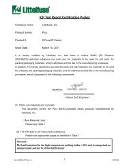
Shown in Figure 1, each active input has a pair of SCRs to<br />
provide dual polarity protection directly in the signal interface.<br />
+ESD<br />
PULSE<br />
INPUT<br />
IN<br />
TO<br />
PROTECTED<br />
IC INPUT<br />
<strong>SP721</strong><br />
To meet the needs of a high performance application, a<br />
protection device must have a wide dynamic operating range<br />
with minimal loading. The <strong>SP720</strong>, <strong>SP721</strong> <strong>and</strong> <strong>SP723</strong> have a<br />
wide dynamic operating range of 35V with low input<br />
capacitance <strong>and</strong> low leakage while still providing the rugged<br />
level of protection necessary for most signal interface<br />
requirements. Low capacitance loading is essential for a fast<br />
ESD protection response time. The input capacitance of the<br />
<strong>SP720</strong> <strong>and</strong> <strong>SP721</strong> is typically 3pF <strong>and</strong> for the <strong>SP723</strong> is 5pF.<br />
Each IN input has typically 5nA of leakage <strong>and</strong> the quiescent<br />
power supply current has 50nA of current.<br />
The SCR cell structure was chosen for both a fast turn-on<br />
response <strong>and</strong> a low series resistance path to the high<br />
current of an ESD discharge. The SCR has a characteristic<br />
of decreasing resistance with increasing current, typically<br />
decreasing to 1Ω<br />
at 2A peak current. Positive <strong>and</strong> negative<br />
SCR cells are paired to work as active switches. The energy<br />
of an ESD discharge is both absorbed <strong>and</strong> shunted by the<br />
SCR to the supply line (positive pulse) or ground (negative<br />
pulse). When the energy is dissipated, the SCR quickly<br />
10-70<br />
V-<br />
VCC SUPPLY<br />
FORWARD SCR<br />
PROTECTION CELL<br />
(ON)<br />
REVERSE SCR<br />
PROTECTION CELL<br />
(OFF)<br />
GND<br />
FIGURE 1. AN ILLUSTRATION OF <strong>SP721</strong> ESD PROTECTION<br />
FOR A POSITIVE ESD PULSE, THE FORWARD<br />
SCR CELL CONDUCTS CURRENT TO THE V CC<br />
SUPPLY<br />
V+<br />
<strong>SP720</strong>, <strong>SP721</strong> <strong>and</strong> <strong>SP723</strong> <strong>Turn</strong>-<strong>On</strong> <strong>and</strong><br />
<strong>Turn</strong>-<strong>Off</strong> Characteristics<br />
Application Note March 1997<br />
1-800-999-9445 or 1-847-824-1188 |<br />
AN9708<br />
returns to its off state because there is no current to sustain<br />
the latched holding condition of the SCR.<br />
<strong>Turn</strong>-<strong>On</strong> Time of the <strong>SP721</strong>AP<br />
Figure 1 shows the paired SCR cell configuration of the<br />
<strong>SP721</strong> with an illustration of how it responds to a positive<br />
ESD pulse applied to the input. The top or forward SCR cell<br />
responds to a positive ESD pulse <strong>and</strong> turns on when the<br />
voltage at the IN input is one VBE<br />
greater than the voltage of<br />
the V+ terminal. ESD pulse current is conducted from the IN<br />
input to V+. The V+ of the <strong>SP721</strong> is common to the VCC<br />
power<br />
supply line of the IC being protected. The SCR begins to<br />
conduct in ~0.7ns <strong>and</strong> has a typical turn-on delay time of 2ns.<br />
To illustrate the turn-on characteristic <strong>and</strong> speed of the SCR,<br />
Figure 2 shows the Human Body Model ESD pulse simulator<br />
per MIL-STD-883D, Method 3015.7. This circuit discharges a<br />
100pF capacitor through 1500Ω<br />
to a device under test<br />
(DUT). The waveform <strong>Turn</strong>-ON characteristic for current vs.<br />
time of an SP72/1 when activated by a +2kV ESD pulse is<br />
shown in Figure 3. The <strong>SP720</strong>, <strong>SP721</strong> <strong>and</strong> <strong>SP723</strong> have the<br />
same cell design <strong>and</strong> turn-on characteristic.<br />
± HIGH<br />
VOLTAGE<br />
SUPPLY<br />
R1 1MΩ TO<br />
10MΩ 1 2<br />
S 1<br />
C 1<br />
100pF<br />
R2 1500Ω<br />
Author: Wayne Austin<br />
DUT<br />
SOCKET<br />
CURRENT<br />
SENSE<br />
SHORT<br />
SWITCH S 1 IN POSITION 1 CHARGES CAPACITOR C 1 . WHEN<br />
S 1 IS SWITCHED TO POSITION 2, CAPACITOR C 1 DISCHARGES<br />
INTO R 1 AND THE DEVICE UNDER TEST (DUT). THE DUT<br />
SOCKET IS SHORTED PIN-TO-PIN FOR SIMULATOR WAVEFORM<br />
VERIFICATION. AN OSCILLOSCOPE CURRENT PROBE IS USED<br />
TO SENSE THE DISCHARGE CURRENT WAVEFORM.<br />
FIGURE 2. MIL-STD-883D, METHOD 3015.7 ESD TEST<br />
CIRCUIT SHOWING THE CURRENT WAVEFORM<br />
VERIFICATION SETUP FOR THE HBM TEST<br />
FIXTURE<br />
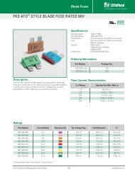
Figure 3 shows waveforms of switching time vs current for<br />
the <strong>SP721</strong>. The top display is a full scale view of an <strong>SP721</strong><br />
ESD discharge waveform vs a reference short circuit<br />
(calibration) discharge waveform for the test fixture of<br />
Figure 2. The bottom display is an exp<strong>and</strong>ed view for both<br />
curves with the same zero reference for the <strong>SP721</strong> turn-on<br />
waveform “B” vs the input reference waveform “A”. (The zero<br />
baselines of both waveforms are initially offset 0.35ns by the<br />
threshold of the scope trigger level.) The turn-on delay of the<br />
<strong>SP721</strong> SCR increases to just over 2ns from the reference<br />
input waveform “A” <strong>and</strong> then drops back to less than 2ns.<br />
Copyright © <strong>Littelfuse</strong>, Inc. 1997
CURRENT (A)<br />
CURRENT (A)<br />
0.0<br />
0<br />
0<br />
10-71<br />
1.6A PEAK(B)<br />
HORIZONTAL SCALE: 200ns/DIV.<br />
VERTICAL SCALE: 400mA/DIV.<br />
WAVEFORM B OFFSET +2kV DIV.<br />
FROM WAVEFORM A<br />
BOTH A AND B WAVEFORMS<br />
SHOW CURRENT FOR +2kV<br />
ESD PULSE<br />
1.3A PEAK(A)<br />
-1.0 0 +1.0<br />
TIME (µs)<br />
1.2<br />
1.0<br />
0.8<br />
0.6<br />
0.4<br />
0.2<br />
.<br />
0.7ns<br />
VERIFICATION<br />
CURRENT INPUT<br />
WAVEFORM<br />
Application Note 9708<br />
2.18ns<br />
A<br />
FIGURE 3A.<br />
FIGURE 3B.<br />
FIGURE 3. OSCILLOSCOPE WAVEFORMS SHOWING CURRENT vs TIME FOR THE MIL-STD-883D, METHOD 3015.7 TEST CIRCUIT OF<br />
FIGURE 2. FIGURE 3A IS A FULL SCALE OF ESD DISCHARGE TIME AS SHOWN ON A HP54540A DIGITAL OSCILLOSCOPE.<br />
FIGURE 3B SHOWS AN EXPANDED VIEW WITH AN OVERLAY OF THE REFERENCE OR SHORTED FIXTURE WAVEFORM<br />
“A” FOR VERIFICATION (CALIBRATION) AND WAVEFORM “B” AS THE SCR TURN-ON AND DELAY TIME RESPONSE. THE<br />
SCR TURN-ON DELAY TIME IS TYPICALLY 2ns.<br />
B<br />
1.74ns<br />
A<br />
<strong>SP721</strong> SCR<br />
CURRENT<br />
WAVEFORM<br />
VERIFICATION<br />
CURRENT INPUT<br />
WAVEFORM<br />
OSCILLOSCOPE WAVEFORMS<br />
CURVE A - REFERENCE INPUT ESD<br />
DISCHARGE CURRENT WAVEFORM FOR<br />
AN ESD PULSE OF +2kV INTO THE<br />
EMPTY TEST FIXTURE SOCKET AND<br />
A PIN-TO-PIN SHORT (SEE FIG. 2)<br />
CURVE B - WAVEFORM FOR AN <strong>SP721</strong><br />
IN THE DUT SOCKET WITH THE SHORT<br />
REMOVED AND THE SAME +2kV ESD<br />
PULSE VOLTAGE DISCHARGED INTO<br />
THE SCR (IN) INPUT OF THE <strong>SP721</strong>.<br />
0 2 4 6 8 10<br />
TIME (ns)<br />
B<br />
<strong>SP721</strong> SCR<br />
CURRENT<br />
WAVEFORM
The 1500Ω<br />
of the st<strong>and</strong>ard test circuit should allow an initial<br />
peak current of 1.33A when the capacitor C1<br />
charge is 2kV.<br />
Current through the <strong>SP721</strong> peaks at 1.6A <strong>and</strong> is then quickly<br />
damped. Lead inductance <strong>and</strong> stray capacitance at the input<br />
causes some transient ringing <strong>and</strong> overshoot. After a few<br />
nanoseconds of ringing, the fall time of the <strong>SP721</strong> current<br />
waveform “B” (shown in the top display) is identical to the<br />
reference waveform “A”.<br />
Speed vs ESD Rated Capability<br />
For any application, the maximum rated ESD capability is most<br />
desirable. However, this is a trade-off with performance related<br />
parameters such frequency (Mb or MHz), static or dynamic<br />
impedance <strong>and</strong> stability. The <strong>SP720</strong>, <strong>SP721</strong> <strong>and</strong> <strong>SP723</strong> offer<br />
an optimal trade-off, having high HBM ESD voltage capability to<br />
both MIL-STD-883 <strong>and</strong> IEC 1000-4-2 st<strong>and</strong>ards with very low<br />
capacitance <strong>and</strong> are designed to work in the signal interface to<br />
protect sensitive ICs. Many competitive ESD protection<br />
products have high capacitance <strong>and</strong> can only be used for<br />
power supply or power line protection.<br />
SCR Structure vs a Zener Device<br />
What is the advantage of the SCR over a Zener diode? While it<br />
is relative simple to suggest that Zener diode may offer more<br />
capability, increasing area for improved ESD ratings increases<br />
the capacitance of the Zener junction. When a Zener becomes<br />
active, dissipation at the junction is the Zener voltage times the<br />
current. When the SCR structure becomes active, it latches on<br />
with low resistance <strong>and</strong> low internal dissipation.<br />
SCR Unlatch Speed<br />
The SCR quickly unlatches when the current drops to zero.<br />
Figure 3A shows the full waveform for turn-on <strong>and</strong> turn-off time.<br />
The <strong>SP721</strong> waveform “B” closely follows the reference input<br />
waveform “A”. Delay in the SCR turn-off is not significantly<br />
longer than the disruptive period of the simulated ESD pulse.<br />
Latch<br />
It should be noted that “latch” as referenced in the turn-on of<br />
the SCR has no relation to latching input problems that were<br />
common in older CMOS devices <strong>and</strong> may occasionally occur<br />
FORWARD SCR<br />
PROTECTION CELL<br />
SIGNAL<br />
LINE<br />
INPUT<br />
10-72<br />
IN<br />
REVERSE SCR<br />
PROTECTION CELL<br />
Application Note 9708<br />
V+<br />
V-<br />
R I<br />
CMOS<br />
INPUT<br />
as an irregularity in other processes. The SCR cells are<br />
designed to latch on with a disruptive signal that is greater<br />
than the supply voltage (V+) or less than ground (V-). The<br />
SCR falls out of latch when input voltage returns to a normal<br />
mode of operation.<br />
How Best to Protect a CMOS IC Input<br />
Figure 4 illustrates an <strong>SP720</strong>, <strong>SP721</strong> or <strong>SP723</strong> interface<br />
with a typical CMOS IC input circuit. This example shows a<br />
typical input for high speed CMOS which includes an internal<br />
series resistor RP<br />
to stacked protection diodes, followed by a<br />
resistor <strong>and</strong> diode. RP<br />
is typically an integral polysilicon<br />
resistor with a resistance of 120Ω<br />
<strong>and</strong> can be subjected to<br />
ESD damage for voltage levels higher than 2kV. Use of an<br />
<strong>SP720</strong>, <strong>SP721</strong> or <strong>SP723</strong> will substantially improve the signal<br />
line input against an ESD discharge.<br />
While the conducting SCR will clamp an ESD pulse, the<br />
discharge current will cause some ride-up of the voltage on<br />
the signal input line. For example, an HBM ESD discharge of<br />
+3kV (see Figure 2) will cause approximately 2A of current.<br />
With this positive input current, the input voltage will exceed<br />
the VCC<br />
level <strong>and</strong> turn-on the forward SCR. The data sheet<br />
I-V curve indicates that the forward voltage drop of the SCR<br />
for 2A will be typically 3V. As such, it is recommended that a<br />
series resistor be used at the CMOS input (shown here as<br />
R1).<br />
This will add resistance to limit current into the CMOS<br />
IC by forming a current divider with the latched-on SCR.<br />
Without R1,<br />
diode D1<br />
would see a 3V forward turn-on or<br />
(3V - 0.7V)/(120) = 19.2mA. A typically HC CMOS should<br />
tolerate twice this level. However, an external resistor of<br />
120Ω<br />
would further reduce the current by one-half. An IC<br />
with a 2kV rated input can be protected to 10kV or higher,<br />
depending on the CMOS internal network <strong>and</strong> resistor, R1.<br />
It is recommended to use the largest value of R1<br />
that is<br />
permitted, consistent with the trade-off in circuit performance.<br />
In layout, it is also recommended to keep the signal line input<br />
layout as short as possible to minimize ringing <strong>and</strong> transients<br />
caused by stray inductance <strong>and</strong> capacitance.<br />
R P<br />
V CC<br />
D 1<br />
D 2<br />
CMOS IC DEVICE<br />
D 3<br />
ESD PROT.<br />
NETWORK<br />
CMOS<br />
LOGIC<br />
FIGURE 4. <strong>SP720</strong>, <strong>SP721</strong> OR <strong>SP723</strong> SCR INTERFACE TO A CMOS INPUT WITH R I ADDED TO ILLUSTRATE MORE EFFECTIVE ESD<br />
PROTECTION FOR CMOS DEVICES<br />
GND