Explanation of Maximum Ratings and Characteristics for ... - Littelfuse
Explanation of Maximum Ratings and Characteristics for ... - Littelfuse
Explanation of Maximum Ratings and Characteristics for ... - Littelfuse

Create successful ePaper yourself
Turn your PDF publications into a flip-book with our unique Google optimized e-Paper software.
Teccor ® br<strong>and</strong> Thyristors<br />
AN1008<br />
<strong>Explanation</strong> <strong>of</strong> <strong>Maximum</strong> <strong>Ratings</strong> <strong>and</strong> <strong>Characteristics</strong> <strong>for</strong> Thyristors<br />
Introduction<br />
Data sheets <strong>for</strong> SCRs <strong>and</strong> Triacs give vital in<strong>for</strong>mation<br />
regarding maximum ratings <strong>and</strong> characteristics <strong>of</strong><br />
Thyristors. If the maximum ratings <strong>of</strong> the Thyristors<br />
are surpassed, possible irreversible damage may occur.<br />
The characteristics describe various pertinent device<br />
parameters which are guaranteed as either minimums or<br />
maximums. Some <strong>of</strong> these characteristics relate to the<br />
ratings but are not ratings in themselves. The characteristic<br />
does not define what the circuit must provide or be<br />
restricted to, but defines the device characteristic. For<br />
<br />
because this value depicts the guaranteed worst-case limit<br />
<br />
value represents the maximum limit that the circuit should<br />
allow.<br />
<strong>Maximum</strong> <strong>Ratings</strong><br />
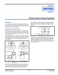
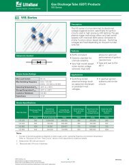
V RRM<br />
: Peak Repetitive Reverse Voltage -- SCR<br />
The peak repetitive reverse voltage rating is the maximum<br />
peak reverse voltage that may be continuously applied to<br />
the main terminals (anode, cathode) <strong>of</strong> an SCR. (Figure<br />
AN1008.1) An open-gate condition <strong>and</strong> gate resistance<br />
termination is designated <strong>for</strong> this rating. An increased<br />
reverse leakage can result due to a positive gate bias<br />
during the reverse voltage exposure time <strong>of</strong> the SCR.<br />
The repetitive peak reverse voltage rating relates to<br />
case temperatures up to the maximum rated junction<br />
temperature.<br />
(anode, cathode) <strong>of</strong> an SCR. This rating represents the<br />
maximum voltage the SCR should be required to block<br />
in the <strong>for</strong>ward direction. The SCR may or may not go into<br />
conduction at voltages above the V DRM<br />
rating. This rating is<br />
specified <strong>for</strong> an open-gate condition <strong>and</strong> gate resistance<br />
termination. A positive gate bias should be avoided since<br />
it will reduce the <strong>for</strong>ward-voltage blocking capability. The<br />
peak repetitive <strong>for</strong>ward (<strong>of</strong>f-state) voltage rating applies<br />
<strong>for</strong> case temperatures up to the maximum rated junction<br />
temperature.<br />
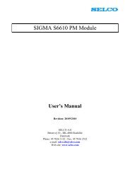
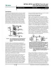
Triac<br />
The peak repetitive <strong>of</strong>f-state voltage rating should not<br />
be surpassed on a typical, non-transient, working basis.<br />
(Figure AN1008.2) V DRM<br />
should not be exceeded even<br />
instantaneously. This rating applies <strong>for</strong> either positive or<br />
negative bias on main terminal 2 at the rated junction<br />
temperature. This voltage is less than the minimum<br />
breakover voltage so that breakover will not occur during<br />
operation. Leakage current is controlled at this voltage so<br />
that the temperature rise due to leakage power does not<br />
contribute significantly to the total temperature rise at<br />
rated current.<br />
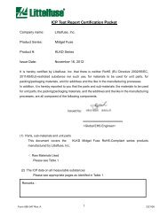
-V<br />
Voltage Drop (v T ) at<br />
Specified Current (i T )<br />
Minimum Holding<br />
Current (I H )<br />
+I<br />
Latching Current (I L )<br />
Off-state Leakage<br />
Current – (I DRM ) at<br />
Specified V DRM<br />
+V<br />
AN1008<br />
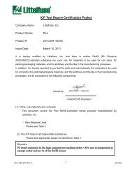
Voltage Drop (v T ) at<br />
Specified Current (i T )<br />
+I<br />
Latching Current (I L )<br />
Specified Minimum<br />
Off-state<br />
Blocking<br />
Voltage (V DRM )<br />
Reverse Leakage<br />
Current - (I RRM ) at<br />
Specified V RRM<br />
-V<br />
Figure AN1008.1<br />
Minimum Holding<br />
Current (I H )<br />
Specified Minimum<br />
Reverse Blocking<br />
Voltage (V RRM )<br />
Reverse<br />
Breakdown<br />
Voltage<br />
Specified Minimum<br />
Off - State<br />
Blocking<br />
Voltage (V DRM )<br />
©2008 <strong>Littelfuse</strong>, Inc.<br />
Specifications are subject to change without notice.<br />
Please refer to http://www.littelfuse.com <strong>for</strong> current in<strong>for</strong>mation.<br />
-I<br />
Forward<br />
Breakover<br />
Voltage<br />
Off - State Leakage<br />
Current - (I DRM ) at<br />
Specified V DRM<br />
V-I <strong>Characteristics</strong> <strong>of</strong> SCR Device<br />
V DRM<br />
: Peak Repetitive Forward (Off-state) Voltage<br />
SCR<br />
The peak repetitive <strong>for</strong>ward (<strong>of</strong>f-state) voltage rating (Figure<br />
AN1008.1) refers to the maximum peak <strong>for</strong>ward voltage<br />
which may be applied continuously to the main terminals<br />
+V<br />
Figure AN1008.2<br />
I T<br />
: Current Rating<br />
SCR<br />
-I<br />
Breakover<br />
Voltage<br />
V-I <strong>Characteristics</strong> <strong>of</strong> Triac Device<br />
For RMS <strong>and</strong> average currents, the restricting factor is<br />
usually confined so that the power dissipated during the<br />
on state <strong>and</strong> as a result <strong>of</strong> the junction-to-case thermal<br />
resistance will not produce a junction temperature in<br />
excess <strong>of</strong> the maximum junction temperature rating.<br />
Power dissipation is changed to RMS <strong>and</strong> average current<br />
ratings <strong>for</strong> a 60 Hz sine wave with a 180º conduction angle.<br />
The average current <strong>for</strong> conduction angles less than 180º<br />
is derated because <strong>of</strong> the higher RMS current connected<br />
with high peak currents. The DC current rating is higher<br />
than the average value <strong>for</strong> 180º conduction since no RMS<br />
component is present.<br />
<strong>Explanation</strong> <strong>of</strong> <strong>Maximum</strong> <strong>Ratings</strong> <strong>and</strong> <strong>Characteristics</strong> <strong>for</strong> Thyristors
Teccor ® br<strong>and</strong> Thyristors<br />
AN1008<br />
The dissipation <strong>for</strong> non-sinusoidal waveshapes can<br />
be determined in several ways. Graphically plotting<br />
instantaneous dissipation as a function <strong>of</strong> time is one<br />
method. The total maximum allowable power dissipation<br />
(P D<br />
) may be determined using the following equation <strong>for</strong><br />
temperature rise:<br />
T J(MAX)<br />
–T C<br />
P D<br />
=<br />
R JC<br />
where T J<br />
(max) is the maximum rated junction temperature<br />
(at zero rated current), T C<br />
is the actual operating case<br />
temperature, <strong>and</strong> R JC<br />
is the published junction-to-case<br />
thermal resistance. Transient thermal resistance curves are<br />
required <strong>for</strong> short interval pulses.<br />
Triac<br />
The limiting factor <strong>for</strong> RMS current is determined by<br />
multiplying power dissipation by thermal resistance. The<br />
resulting current value will ensure an operating junction<br />
temperature within maximum value. For convenience,<br />
dissipation is converted to RMS current at a 360º<br />
conduction angle. The same RMS current can be used at<br />
a conduction angle <strong>of</strong> less than 360º. For in<strong>for</strong>mation on<br />
non-sinusoidal waveshapes <strong>and</strong> a discussion <strong>of</strong> dissipation,<br />
refer to the preceding description <strong>of</strong> SCR current rating.<br />
I TSM<br />
: Peak Surge (Non-repetitive) On-state Current --<br />
SCR <strong>and</strong> Triac<br />
The peak surge current is the maximum peak current<br />
that may be applied to the device <strong>for</strong> one full cycle <strong>of</strong><br />
conduction without device degradation. The maximum<br />
peak current is usually specified as sinusoidal at 50 Hz or<br />
60 Hz. This rating applies when the device is conducting<br />
rated current be<strong>for</strong>e the surge <strong>and</strong>, thus, with the junction<br />
temperature at rated values be<strong>for</strong>e the surge. The junction<br />
temperature will surpass the rated operating temperature<br />
during the surge, <strong>and</strong> the blocking capacity may be<br />
decreased until the device reverts to thermal equilibrium.<br />
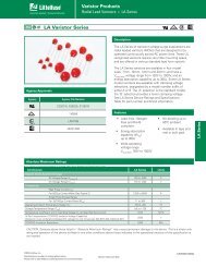
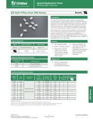
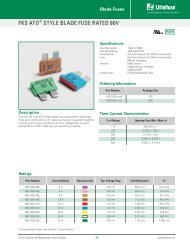
The surge-current curve in Figure AN1008.3 illustrates the<br />
peak current that may be applied as a function <strong>of</strong> surge<br />
duration. This surge curve is not intended to depict an<br />
exponential current decay as a function <strong>of</strong> applied overload.<br />
Instead, the peak current shown <strong>for</strong> a given number <strong>of</strong><br />
cycles is the maximum peak surge permitted <strong>for</strong> that<br />
time period. The current must be derated so that the peak<br />
junction temperature during the surge overload does not<br />
exceed maximum rated junction temperature if blocking is<br />
to be retained after a surge.<br />
Peak Surge (Non-repetitive)<br />
On-state Current (I TSM ) – Amps<br />
1000<br />
400<br />
300<br />
250<br />
150<br />
120<br />
100<br />
80<br />
60<br />
50<br />
40<br />
30<br />
20<br />
SUPPLY FREQUENCY: 60 Hz Sinusoidal<br />
LOAD: Resistive<br />
RMS ON-STATE CURRENT [IT(RMS)]:<br />
<strong>Maximum</strong> Rated Value at Specified<br />
Case Temperature<br />
40 A TO-218<br />
25 A T0-220<br />
Notes:<br />
1) Gate control may be lost<br />
during <strong>and</strong> immediately<br />
following surge current interval.<br />
2) Overload may not be repeated<br />
until junction temperature has<br />
returned to steady-state<br />
rated value.<br />
15 A TO-220<br />
10<br />
1 10 100 1000<br />
Figure AN1008.3<br />
Surge Current Duration – Full Cycles<br />
Peak Surge Current versus Surge Current<br />
Duration<br />
I TM<br />
: Peak Repetitive On-state Current – SCR <strong>and</strong> Triac<br />
The I TM<br />
rating specifies the maximum peak current that<br />
may be applied to the device during brief pulses. When<br />
the device operates under these circumstances, blocking<br />
capability is maintained. The minimum pulse duration<br />
<br />
operating voltage, the duty factor, the case temperature,<br />
<strong>and</strong> the gate wave<strong>for</strong>m are also defined. This rating<br />
must be followed when high repetitive peak currents<br />
are employed, such as in pulse modulators, capacitivedischarge<br />
circuits, <strong>and</strong> other applications where snubbers<br />
are required.<br />
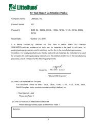
di/dt: Rate-<strong>of</strong>-change <strong>of</strong> On-state Current – SCR<br />
<strong>and</strong> Triac<br />
<br />
current through a Thyristor device during turn-on. The value<br />
<strong>of</strong> principal voltage prior to turn-on <strong>and</strong> the magnitude <strong>and</strong><br />
rise time <strong>of</strong> the gate trigger wave<strong>for</strong>m during turn-on are<br />
among the conditions under which the rating applies. If<br />
<br />
<br />
<br />
localized heating may cause device degradation.<br />
During the first few microseconds <strong>of</strong> initial turn-on, the<br />
<br />
the Thyristor is greatly increased as soon as the total area<br />
<strong>of</strong> the pellet is in full conduction.<br />
<br />
or transient turn-on (non-gated) is not related to this<br />
<br />
temperature.<br />
<br />
can be calculated by means <strong>of</strong> the following equation.<br />
di I TM<br />
---- = -----<br />
dt 2 t1<br />
<strong>Explanation</strong> <strong>of</strong> <strong>Maximum</strong> <strong>Ratings</strong> <strong>and</strong> <strong>Characteristics</strong> <strong>for</strong> Thyristors<br />
©2008 <strong>Littelfuse</strong>, Inc.<br />
Specifications are subject to change without notice.<br />
Please refer to http://www.littelfuse.com <strong>for</strong> current in<strong>for</strong>mation.
Teccor ® br<strong>and</strong> Thyristors<br />
AN1008<br />
Current<br />
I TM<br />
50%<br />
di I<br />
= TM<br />
dt 2t 1<br />
V DM = Off-state voltage<br />
prior to switching<br />
resistance termination. Positive gate bias lowers the<br />
breakover voltage. Breakover is temperature sensitive <strong>and</strong><br />
will occur at a higher voltage if the junction temperature<br />
is kept below maximum T J<br />
value. If SCRs <strong>and</strong> Triacs are<br />
turned on as a result <strong>of</strong> an excess <strong>of</strong> breakover voltage,<br />
instantaneous power dissipations may be produced that<br />
can damage the chip or die.<br />
AN1008<br />
10%<br />
Figure AN1008.4<br />
0 t 1<br />
t<br />
I 2 t Rating -- SCR <strong>and</strong> Triac<br />
Time<br />
©2008 <strong>Littelfuse</strong>, Inc.<br />
Specifications are subject to change without notice.<br />
Please refer to http://www.littelfuse.com <strong>for</strong> current in<strong>for</strong>mation.<br />
Relationship <strong>of</strong> <strong>Maximum</strong> Current Rating to<br />
Time<br />
The I 2 t rating gives an indication <strong>of</strong> the energy-absorbing<br />
capability <strong>of</strong> the Thyristor device during surge-overload<br />
conditions. The rating is the product <strong>of</strong> the square <strong>of</strong> the<br />
RMS current (I RMS<br />
) 2 that flows through the device <strong>and</strong> the<br />
time during which the current is present <strong>and</strong> is expressed<br />
in A 2 s. This rating is given <strong>for</strong> fuse selection purposes. It is<br />
important that the I 2 t rating <strong>of</strong> the fuse is less than that <strong>of</strong><br />
the Thyristor device. Without proper fuse or current limit,<br />
overload or surge current will permanently damage the<br />
device due to excessive junction heating.<br />
P G<br />
: Gate Power Dissipation -- SCR <strong>and</strong> Triac<br />
Gate power dissipation ratings define both the peak power<br />
(P GM<br />
) <strong>for</strong>ward or reverse <strong>and</strong> the average power (P G(AV)<br />
)<br />
that may be applied to the gate. Damage to the gate can<br />
occur if these ratings are not observed. The width <strong>of</strong> the<br />
applied gate pulses must be considered in calculating the<br />
voltage <strong>and</strong> current allowed since the peak power allowed<br />
is a function <strong>of</strong> time. The peak power that results from a<br />
given signal source relies on the gate characteristics <strong>of</strong> the<br />
specific unit. The average power resulting from high peak<br />
powers must not exceed the average-power rating.<br />
T S<br />
, T J<br />
: Temperature Range -- SCR <strong>and</strong> Triac<br />
The maximum storage temperature (T S<br />
) is greater than<br />
the maximum operating temperature (actually maximum<br />
junction temperature). <strong>Maximum</strong> storage temperature<br />
is restricted by material limits defined not so much by<br />
the silicon but by peripheral materials such as solders<br />
<br />
encapsulating epoxy. The <strong>for</strong>ward <strong>and</strong> <strong>of</strong>f-state blocking<br />
capability <strong>of</strong> the device determines the maximum junction<br />
(T J<br />
) temperature. <strong>Maximum</strong> blocking voltage <strong>and</strong> leakage<br />
current ratings are established at elevated temperatures<br />
near maximum junction temperature; there<strong>for</strong>e, operation<br />
in excess <strong>of</strong> these limits may result in unreliable operation<br />
<strong>of</strong> the Thyristor.<br />
<strong>Characteristics</strong><br />
V BO<br />
: Instantaneous Breakover Voltage -- SCR <strong>and</strong> Triac<br />
Breakover voltage is the voltage at which a device turns<br />
on (switches to on state by voltage breakover). (Figure<br />
AN1008.1) This value applies <strong>for</strong> open-gate or gate-<br />
I DRM<br />
: Peak Repetitive Off-state (Blocking) Current<br />
SCR<br />
I DRM<br />
is the maximum leakage current permitted through<br />
the SCR when the device is <strong>for</strong>ward biased with rated<br />
positive voltage on the anode (DC or instantaneous) at<br />
rated junction temperature <strong>and</strong> with the gate open or<br />
gate resistance termination. A 1000 Ω resistor connected<br />
between gate <strong>and</strong> cathode is required on all sensitive<br />
SCRs. Leakage current decreases with decreasing junction<br />
temperatures. Effects <strong>of</strong> the <strong>of</strong>f-state leakage currents on<br />
the load <strong>and</strong> other circuitry must be considered <strong>for</strong> each<br />
circuit application. Leakage currents can usually be ignored<br />
in applications that control high power.<br />
Triac<br />
<br />
<strong>for</strong> the Triac is the same as <strong>for</strong> the SCR except that it<br />
applies with either positive or negative bias on main<br />
terminal 2.(Figure AN1008.2)<br />
I RRM<br />
: Peak Repetitive Reverse Current – SCR<br />
This characteristic is essentially the same as the peak<br />
<br />
voltage is applied to the anode (reverse biased).<br />
V TM<br />
: Peak On-State Voltage -- SCR <strong>and</strong> Triac<br />
The instantaneous on-state voltage (<strong>for</strong>ward drop) is the<br />
principal voltage at a specified instantaneous current <strong>and</strong><br />
case temperature when the Thyristor is in the conducting<br />
state. To prevent heating <strong>of</strong> the junction, this characteristic<br />
is measured with a short current pulse. The current pulse<br />
should be at least 100 μs duration to ensure the device<br />
is in full conduction. The <strong>for</strong>ward-drop characteristic<br />
determines the on-state dissipation. See Figure AN1008.5,<br />
<strong>and</strong> refer to “IT: Current Rating” on page AN1008-2.<br />
Positive or Negative<br />
Instantaneous On-state Current (i T<br />
) – Amps<br />
Figure AN1008.5<br />
90<br />
80<br />
70<br />
60<br />
50<br />
40<br />
30<br />
20<br />
10<br />
0<br />
T C<br />
= 25 °C<br />
40 A TO-218<br />
15 <strong>and</strong> 25 A TO-220<br />
0 0.6 0.8 1.0 1.2 1.4 1.6 1.8<br />
Positive or Negative<br />
Instantaneous On-state Voltage (v T<br />
) – Volts<br />
On-state Current versus On-state Voltage<br />
(Typical)<br />
<strong>Explanation</strong> <strong>of</strong> <strong>Maximum</strong> <strong>Ratings</strong> <strong>and</strong> <strong>Characteristics</strong> <strong>for</strong> Thyristors
Teccor ® br<strong>and</strong> Thyristors<br />
AN1008<br />
I GT<br />
: DC Gate Trigger Current<br />
SCR<br />
I GT<br />
is the minimum DC gate current required to cause<br />
the Thyristor to switch from the non-conducting to the<br />
conducting state <strong>for</strong> a specified load voltage <strong>and</strong> current<br />
as well as case temperature. The characteristic curve<br />
illustrated in Figure AN1008.6 shows that trigger current<br />
is temperature dependent. The Thyristor becomes less<br />
sensitive (requires more gate current) with decreasing<br />
junction temperatures. The gate current should be<br />
increased by a factor <strong>of</strong> two to five times the minimum<br />
threshold DC trigger current <strong>for</strong> best operation. Where<br />
<br />
temperatures are expected, the gate pulse may be 10<br />
times the minimum IGT, plus it must be fast-rising <strong>and</strong> <strong>of</strong><br />
sufficient duration in order to properly turn on the Thyristor.<br />
V GT<br />
: DC Gate Trigger Voltage<br />
SCR<br />
V GT<br />
is the DC gate-cathode voltage that is present just<br />
prior to triggering when the gate current equals the DC<br />
trigger current. As shown in the characteristic curve in<br />
Figure AN1008.8, the gate trigger voltage is higher at lower<br />
temperatures. The gate-cathode voltage drop can be higher<br />
than the DC trigger level if the gate is driven by a current<br />
higher than the trigger current.<br />
Triac<br />
The difference in V GT<br />
<strong>for</strong> the SCR <strong>and</strong> the Triac is that the<br />
Triac can be fired in four possible modes. The threshold<br />
trigger voltage can be slightly different, depending on<br />
which <strong>of</strong> the four operating modes is actually used.<br />
2.0<br />
4.0<br />
I GT<br />
I GT<br />
(T J<br />
= 25 °C)<br />
3.0<br />
2.0<br />
V GT<br />
Ratio <strong>of</strong><br />
V GT (T J = 25 °C)<br />
1.5<br />
1.0<br />
.5<br />
Ratio <strong>of</strong><br />
1.0<br />
0<br />
-65 -40 -15 +25 +65<br />
+125<br />
Junction Temperature (T J ) – °C<br />
0<br />
Figure AN1008.6<br />
-65 -40 -15 +25 +65<br />
+125<br />
Junction Temperature (T J<br />
) – °C<br />
Normalized DC Gate Trigger Current <strong>for</strong> All<br />
Quadrants versus Case Temperature<br />
Triac<br />
The description <strong>for</strong> the SCR applies as well to the Triac<br />
with the addition that the Triac can be fired in four possible<br />
modes (Figure AN1008.7):<br />
Quadrant I (main terminal 2 positive, gate positive)<br />
Quadrant II (main terminal 2 positive, gate negative)<br />
Quadrant III (main terminal 2 negative, gate negative)<br />
Quadrant IV (main terminal 2 negative, gate positive)<br />
I GT<br />
-<br />
Figure AN1008.7<br />
(-) I GT<br />
GATE<br />
(-) I GT<br />
GATE<br />
ALL POLARITIES ARE REFERENCED TO MT1<br />
MT2 POSITIVE<br />
(Positive Half Cycle)<br />
MT2 +<br />
MT2<br />
REF<br />
MT2<br />
REF<br />
MT1<br />
MT1<br />
QII<br />
QIII<br />
QI<br />
QIV<br />
(+) I GT<br />
GATE<br />
(+) I GT<br />
GATE<br />
MT2 NEGATIVE<br />
(Negative Half Cycle)<br />
MT1<br />
<strong>Explanation</strong> <strong>of</strong> <strong>Maximum</strong> <strong>Ratings</strong> <strong>and</strong> <strong>Characteristics</strong> <strong>for</strong> Thyristors<br />
-<br />
REF<br />
MT2<br />
REF<br />
NOTE: Alternistors will not operate in Q IV<br />
MT1<br />
+ I GT<br />
Definition <strong>of</strong> Operating Quadrants<br />
Figure AN1008.8<br />
I L<br />
: Latching Current<br />
Normalized DC Gate Trigger Voltage <strong>for</strong> All<br />
Quadrants versus Case Temperature<br />
SCR<br />
Latching current is the DC anode current above which the<br />
gate signal can be withdrawn <strong>and</strong> the device stays on. It<br />
is related to, has the same temperature dependence as,<br />
<strong>and</strong> is somewhat greater than the DC gate trigger current.<br />
(Figure AN1008.1 <strong>and</strong> Figure AN1008.2) Latching current is<br />
at least equal to or much greater than the holding current,<br />
depending on the Thyristor type.<br />
Latching current is greater <strong>for</strong> fast-rise-time anode currents<br />
<br />
dynamic latching current that determines whether a device<br />
will stay on when the gate signal is replaced with very<br />
short gate pulses. The dynamic latching current varies with<br />
the magnitude <strong>of</strong> the gate drive current <strong>and</strong> pulse duration.<br />
In some circuits, the anode current may oscillate <strong>and</strong> drop<br />
back below the holding level or may even go negative;<br />
hence, the unit may turn <strong>of</strong>f <strong>and</strong> not latch if the gate signal<br />
is removed too quickly.<br />
Triac<br />
The description <strong>of</strong> this characteristic <strong>for</strong> the Triac is the<br />
same as <strong>for</strong> the SCR, with the addition that the Triac can<br />
be latched on in four possible modes (quadrants). Also,<br />
the required latching is significantly different depending<br />
on which gating quadrants are used. Figure AN1008.9<br />
illustrates typical latching current requirements <strong>for</strong> the four<br />
possible quadrants <strong>of</strong> operation.<br />
©2008 <strong>Littelfuse</strong>, Inc.<br />
Specifications are subject to change without notice.<br />
Please refer to http://www.littelfuse.com <strong>for</strong> current in<strong>for</strong>mation.
Teccor ® br<strong>and</strong> Thyristors<br />
AN1008<br />
I L — mA<br />
14<br />
12<br />
10<br />
8<br />
6<br />
4<br />
2<br />
I<br />
II<br />
III<br />
IV<br />
This value will be reduced by a positive gate signal. This<br />
characteristic is temperature-dependent <strong>and</strong> is lowest at<br />
the maximum-rated junction temperature. There<strong>for</strong>e, the<br />
characteristic is determined at rated junction temperature<br />
<strong>and</strong> at rated <strong>for</strong>ward <strong>of</strong>f-state voltage which is also a worstcase<br />
situation. Line or other transients which might be<br />
applied to the Thyristor in the <strong>of</strong>f state must be reduced, so<br />
that neither the rate-<strong>of</strong>-rise nor the peak voltage are above<br />
specifications if false firing is to be prevented. Turn-on<br />
<br />
current remains within current ratings <strong>of</strong> the device being<br />
used.<br />
AN1008<br />
Figure AN1008.9<br />
0 1.0 2.0 3.0 4.0 5.0 6.0<br />
I GT — mA<br />
Typical Triac Latching (I L<br />
) Requirements <strong>for</strong><br />
Four Quadrants versus Gate Current (I GT<br />
)<br />
Critical dv/dt<br />
I H<br />
: Holding Current -- SCR <strong>and</strong> Triac<br />
The holding current is the DC principal on-state current<br />
<br />
state after latching <strong>and</strong> gate signal is removed. This current<br />
is equal to or lower in value than the latching current<br />
(Figure AN1008.1 <strong>and</strong> Figure AN1008.2) <strong>and</strong> is related to<br />
<strong>and</strong> has the same temperature dependence as the DC gate<br />
trigger current shown in Figure AN1008.10. Both minimum<br />
<strong>and</strong> maximum holding current may be important. If the<br />
device is to stay in conduction at low-anode currents, the<br />
maximum holding current <strong>of</strong> a device <strong>for</strong> a given circuit<br />
must be considered. The minimum holding current <strong>of</strong> a<br />
device must be considered if the device is expected to<br />
turn <strong>of</strong>f at a low DC anode current. Note that the low DC<br />
principal current condition is a DC turn-<strong>of</strong>f mode, <strong>and</strong> that<br />
an initial on-state current (latching current) is required to<br />
ensure that the Thyristor has been fully turned on prior to a<br />
holding current measurement.<br />
I H<br />
I H<br />
(T J<br />
= 25 °C)<br />
Ratio <strong>of</strong><br />
4.0<br />
3.0<br />
2.0<br />
1.0<br />
Figure AN1008.10<br />
0<br />
-65 -40 -15 +25 +65<br />
+125<br />
Junction Temperature (T J<br />
) – °C<br />
©2008 <strong>Littelfuse</strong>, Inc.<br />
Specifications are subject to change without notice.<br />
Please refer to http://www.littelfuse.com <strong>for</strong> current in<strong>for</strong>mation.<br />
INITIAL ON-STATE CURRENT<br />
= 400 mA dc<br />
Normalized DC Holding Current versus Case<br />
Temperature<br />
dv/dt, Static: Critical Rate-<strong>of</strong>-rise <strong>of</strong> Off-state Voltage<br />
— SCR <strong>and</strong> Triac<br />
<br />
that a device will hold <strong>of</strong>f, with gate open, without turning<br />
on. Figure AN1008.11 illustrates the exponential definition.<br />
0<br />
V D<br />
Figure AN1008.11<br />
dv V D<br />
= 0.63<br />
dt<br />
t<br />
t = RC<br />
t<br />
63% <strong>of</strong> V D<br />
Exponential Rate-<strong>of</strong>-rise <strong>of</strong> Off-state Voltage<br />
<br />
dv/dt, Commutating: Critical Rate-<strong>of</strong>-rise <strong>of</strong><br />
Commutation Voltage -- Triac<br />
<br />
the main terminals that a Triac can support (block without<br />
switching back on) when commutating from the on state<br />
in one half cycle to the <strong>of</strong>f state in the opposite half<br />
cycle. This parameter is specified at maximum rated case<br />
temperature (equal to T J<br />
) since it is temperature-dependent.<br />
<br />
peak reapplied voltage (line voltage) <strong>and</strong> is specified at<br />
rated current <strong>and</strong> voltage. All devices are guaranteed to<br />
commutate rated current with a resistive load at 50 Hz to<br />
60 Hz. Commutation <strong>of</strong> rated current is not guaranteed<br />
at higher frequencies, <strong>and</strong> no direct relationship can be<br />
<br />
higher-frequency operation. With inductive loading, when<br />
the voltage is out <strong>of</strong> phase with the load current, a voltage<br />
<br />
Triac during the zero-current crossing. (Figure AN1008.12)<br />
A snubber (series RC across the Triac) should be used<br />
<br />
amount below the minimum value which the Triac can be<br />
guaranteed to commutate <strong>of</strong>f each half cycle.<br />
<br />
<br />
<br />
20% lower while I RMS<br />
rating remains the same. (Figure<br />
AN1008.4)<br />
<strong>Explanation</strong> <strong>of</strong> <strong>Maximum</strong> <strong>Ratings</strong> <strong>and</strong> <strong>Characteristics</strong> <strong>for</strong> Thyristors
Teccor ® br<strong>and</strong> Thyristors<br />
AN1008<br />
ESOURCE<br />
IG<br />
di/dt<br />
EM<br />
ITRM<br />
TIME<br />
be reapplied. (Figure AN1008.14) Turn-<strong>of</strong>f time is a function<br />
<strong>of</strong> many parameters <strong>and</strong> very dependent on temperature<br />
<strong>and</strong> gate bias during the turn-<strong>of</strong>f interval. Turn-<strong>of</strong>f time<br />
is lengthened <strong>for</strong> higher temperature so a high junction<br />
temperature is specified. The gate is open during the turn<strong>of</strong>f<br />
interval. Positive bias on the gate will lengthen the turn<strong>of</strong>f<br />
time; negative bias on the gate will shorten it.<br />
IT<br />
(di/dt) C<br />
Voltage across Triac<br />
10%<br />
I TM<br />
di/dt<br />
<br />
63%<br />
V DRM<br />
(dv/dt) C<br />
<br />
Associated Conditions<br />
t gt<br />
: Gate-controlled Turn-on Time -- SCR <strong>and</strong> Triac<br />
50% I TM<br />
50% I RM<br />
i R<br />
Reverse Current<br />
trr<br />
tq<br />
V T<br />
I Off-State Leakage<br />
D<br />
V<br />
Off-State Voltage<br />
D<br />
dv/dt<br />
The t gt<br />
is the time interval between the application <strong>of</strong><br />
a gate pulse <strong>and</strong> the on-state current reaching 90% <strong>of</strong><br />
its steady-state value. (Figure AN1008.13) As would be<br />
expected, turn-on time is a function <strong>of</strong> gate drive. Shorter<br />
turn-on times occur <strong>for</strong> increased gate drives. This turn-on<br />
time is actually only valid <strong>for</strong> resistive loading. For example,<br />
inductive loading would restrict the rate-<strong>of</strong>-rise <strong>of</strong> anode<br />
current. For this reason, this parameter does not indicate<br />
the time that must be allowed <strong>for</strong> the device to stay on if<br />
the gate signal is removed. (Refer to the description <strong>of</strong> “IL:<br />
Latching Current” on page AN1008-4.) However, if the load<br />
was resistive <strong>and</strong> equal to the rated load current value, the<br />
device definitely would be operating at a current above the<br />
dynamic latching current in the turn-on time interval since<br />
current through the device is at 90% <strong>of</strong> its peak value<br />
during this interval.<br />
Gate<br />
Trigger<br />
Pulse<br />
Off-state Voltage<br />
On-state Current<br />
10%<br />
Delay<br />
Time<br />
Turn-on<br />
Time<br />
90%<br />
10%<br />
Rise<br />
Time<br />
10%<br />
90%<br />
50% 50%<br />
Gate Pulse Width<br />
Figure AN1008.14<br />
t1<br />
Waveshapes <strong>of</strong> t q<br />
Rating Test <strong>and</strong> Associated<br />
Conditions<br />
R θJC<br />
, R θJA<br />
: Thermal Resistance (Junction-to-case,<br />
Junction-to-ambient) -- SCR <strong>and</strong> Triac<br />
The thermal-resistance characteristic defines the steadystate<br />
temperature difference between two points at a<br />
given rate <strong>of</strong> heat-energy transfer (dissipation) between<br />
the points. The thermal-resistance system is an analog<br />
to an electrical circuit where thermal resistance is<br />
equivalent to electrical resistance, temperature difference<br />
is equivalent to voltage difference, <strong>and</strong> rate <strong>of</strong> heatenergy<br />
transfer (dissipation) is equivalent to current.<br />
Dissipation is represented by a constant current generator<br />
since generated heat must flow (steady-state) no matter<br />
what the resistance in its path. Junction-to-case thermal<br />
resistance establishes the maximum case temperature at<br />
maximum rated steady-state current. The case temperature<br />
must be held to the maximum at maximum ambient<br />
temperature when the device is operating at rated current.<br />
Junction-to-ambient thermal resistance is established at a<br />
lower steady-state current, where the device is in free air<br />
with only the external heat sinking <strong>of</strong>fered by the device<br />
package itself. For R JA,<br />
power dissipation is limited by<br />
what the device package can dissipate in free air without<br />
any additional heat sink:<br />
Figure AN1008.13<br />
Waveshapes <strong>for</strong> Turn-on Time <strong>and</strong> Associated<br />
Conditions<br />
R JC<br />
=<br />
T J<br />
–T C<br />
P (AV)<br />
t q<br />
: Circuit-commutated Turn-<strong>of</strong>f Time -- SCR<br />
The circuit-commutated turn-<strong>of</strong>f time <strong>of</strong> the device is the<br />
time during which the circuit provides reverse bias to the<br />
device (negative anode) to commutate it <strong>of</strong>f. The turn-<strong>of</strong>f<br />
time occurs between the time when the anode current<br />
goes negative <strong>and</strong> when the anode positive voltage may<br />
T J<br />
–T A<br />
R JA<br />
=<br />
P(AV)<br />
<strong>Explanation</strong> <strong>of</strong> <strong>Maximum</strong> <strong>Ratings</strong> <strong>and</strong> <strong>Characteristics</strong> <strong>for</strong> Thyristors<br />
©2008 <strong>Littelfuse</strong>, Inc.<br />
Specifications are subject to change without notice.<br />
Please refer to http://www.littelfuse.com <strong>for</strong> current in<strong>for</strong>mation.