SECTION A-A SECTION B-B CATCH BASIN No. 8 PLAN OF CATCH ...
SECTION A-A SECTION B-B CATCH BASIN No. 8 PLAN OF CATCH ...
SECTION A-A SECTION B-B CATCH BASIN No. 8 PLAN OF CATCH ...

Create successful ePaper yourself
Turn your PDF publications into a flip-book with our unique Google optimized e-Paper software.
6" Bedding<br />
of #57<br />
Aggregate<br />
2"x" Strap<br />
Variable<br />
See Sht. 2/2 for NOTES<br />
A<br />
2"x 1" Bar<br />
6:1<br />
Outlet pipe<br />
8"<br />
" min. clearance<br />
between grate and<br />
frame at upper edge<br />
37"x2"x"<br />
2<br />
1"x1"x" (min.)<br />
Pipe<br />
pedestal angle (Typ.)<br />
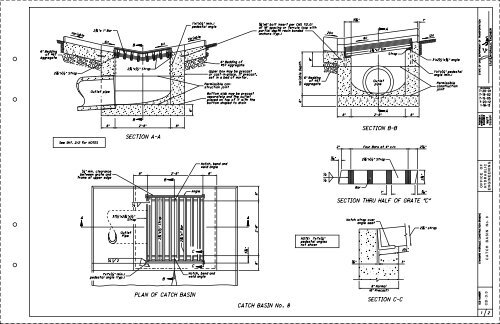
<strong>SECTION</strong> A-A<br />
Outlet<br />
B<br />
2"x" Strap<br />
B<br />
Strap<br />
2’-8"<br />
8"<br />
2 "x " Strap<br />
6:1 Variable<br />
B<br />
B<br />
8"<br />
2’-8"<br />
<strong>PLAN</strong> <strong>OF</strong> <strong>CATCH</strong> <strong>BASIN</strong><br />
2 "x1" Bar<br />
6"<br />
1"x1"x" (min.)<br />
pedestal angle<br />
Angle<br />
C<br />
C<br />
Permissible con-<br />
struction joint<br />
Bottom slab may be precast<br />
separately and the outlet<br />
placed on top of it with the<br />
bottom shaped to drain<br />
<strong>No</strong>tch, bend and<br />
weld angle<br />
8"<br />
<strong>No</strong>tch, bend and<br />
weld angle<br />
6" Bedding of<br />
#57 Aggregate<br />
Upper box may be precast<br />
or cast-in-place. If precast,<br />
set in a bed of mortar.<br />
3 "<br />
A<br />
8" 2’-8"<br />
8"<br />
"x6" bolt insert per CMS 712.01<br />
at 18" spacing or ferrule loop with<br />
partial depth resin bonded<br />
anchors (typ.)<br />
<strong>CATCH</strong> <strong>BASIN</strong> <strong>No</strong>. 8<br />
Variable Depth<br />
6"<br />
8"<br />
6" Bedding<br />
of #57<br />
Aggregate<br />
NOTE: 1"x1"x"<br />
pedestal angles<br />
not shown<br />
20:1<br />
"<br />
8"<br />
3" 1"<br />
Bar<br />
8:1<br />
Outlet<br />
pipe<br />
Strap<br />
<strong>SECTION</strong> B-B<br />
<strong>SECTION</strong> THRU HALF <strong>OF</strong> GRATE "C"<br />
<strong>No</strong>tch strap over<br />
angle seat<br />
A<br />
2 "x1" bar<br />
2’-8"<br />
2" Four Bars at 4" c/c 2"<br />
"<br />
2"x" Strap<br />
A<br />
8" <strong>No</strong>rmal<br />
(6" Precast)<br />
<strong>SECTION</strong> C-C<br />
8"<br />
2 "<br />
1" "<br />
2 "<br />
3"<br />
12:1<br />
2" strap<br />
3"x2"x" angle<br />
1"x1"x" pedestal<br />
angle (min.)<br />
Permissible<br />
construction<br />
joint<br />
STATE <strong>OF</strong> OHIO DEPARTMENT <strong>OF</strong> TRANSPORTATION<br />
STANDARD HYDRAULIC CONSTRUCTION DRAWING<br />
SCD NUMBER<br />
REVISIONS<br />
ROADWAY<br />
HYDRAULIC<br />
ENGINEER<br />
O FFICE O F<br />
C A TC H BA SIN <strong>No</strong>. 8<br />
C B-3.3<br />
1 2<br />
STATE HYDRAULIC ENGINEER<br />
7-20-01<br />
7-19-02<br />
7-15-05<br />
7-20-12<br />
1-18-13<br />
Cozzoli<br />
Matt<br />
ENGINEERING<br />
HY D RA ULIC
Edge of<br />
pavement<br />
7’-6" min.<br />
Ditch Erosion Protection<br />
Ditch Erosion<br />
Protection<br />
Variable Slope<br />
150’<br />
Ditch Erosion Protection<br />
150’<br />
Flowline of ditch<br />
See RIPRAP CUT<strong>OF</strong>F WALL DETAIL<br />
Finish concrete apron<br />
to match slope<br />
<strong>PLAN</strong><br />
center of earth dike<br />
3"<br />
VERTICAL SCALE DISTORTED<br />
PR<strong>OF</strong>ILE<br />
MEDIAN GRADING AT <strong>CATCH</strong> <strong>BASIN</strong><br />
5’<br />
Concrete apron<br />
with cutoff wall<br />
7’ min. to<br />
8’-0"<br />
1’-0"<br />
6" Concrete apron<br />
1’-0"<br />
to center of earth dike<br />
Median centerline<br />
UPSTREAM END VIEW <strong>OF</strong><br />
CONCRETE APRON OR GROUTED RIPRAP<br />
5’<br />
Catch basin<br />
7’ min.<br />
Rounded<br />
12:1 Slope or flatter<br />
Catch basin<br />
Centerline<br />
of ditch<br />
6" Dike unless<br />
Rounded<br />
otherwise noted<br />
Variable<br />
Slope<br />
CONSTRUCTION INFORMATION<br />
Typical weight of grate = 245 lbs.<br />
Typical weight of frame = 65 lbs.<br />
NOTES<br />
GRATE AND FRAME: Use structural steel according to CMS 711.01<br />
and 513. Provide a design essentially the same and equally as<br />
strong as the one shown.<br />
GRATE: Depress the grate 3" below the upstream end of the<br />
concrete apron at the centerline of the ditch.<br />
WALLS: Construct brick or cast-in-place walls with a nominal<br />
thickness of 8" from the bottom slab to the upper box.<br />
PRECAST CONSTRUCTION: Permitted, except for the apron.<br />
Meet the concrete requirements of CMS 706.13. Provide precast<br />
walls at least 6" thick with sufficient reinforcing to permit<br />
shipping and placement without damage. Reduce the wall<br />
thickness from the outside.<br />
STEPS: Provide steps meeting the requirements SCD of MH-1.1<br />
where the depth exceeds 6’.<br />
<strong>BASIN</strong>S OVER 12 FEET DEEP: Use precast or cast-in-place<br />
concrete; reinforce with #4 bars on 12" centers both vertically<br />
and horizontally with 2" clearance from inside wall face.<br />
LOCATION AND ELEVATION: When given on the plans the location<br />
is at the center of the grate. The elevation is the lowest<br />
point on the grate.<br />
OPENINGS: Obtain the Engineer’s approval for any pipe openings<br />
greater than 4" from the outside of the pipe to the structure.<br />
Fill any voids per CMS 611.<br />
CONCRETE APRONS: Construct aprons in such a manner that the<br />
outside edges are at equal elevations.<br />
If specified in the plans, grouted riprap may be used in place<br />
of the concrete apron.<br />
DITCH PROTECTION: Provide a 150’ length of ditch erosion<br />
protection as shown. Installation and payment for the ditch<br />
erosion protection are per CMS 670.<br />
<strong>BASIN</strong>S IN SAG: When in a sag, omit the earth dike and longitudinal<br />
slope of grate, and provide concrete apron and ditch protection<br />
on each side of the basin.<br />
PAYMENT: The concrete apron with cutoff wall or grouted riprap<br />
and dike are incidental Item to 611 - Catch Basin, <strong>No</strong>. 8.<br />
However, the apron is not required when Item 611 - Catch Basin,<br />
<strong>No</strong>. 8, Without Apron, is specified.<br />
When itemized separately, payment for Item 601 Riprap using<br />
6" Reinforced Concrete Slab includes the cost of the cutoff<br />
wall.<br />
2’-6"<br />
9"<br />
9"<br />
Cutoff<br />
wall<br />
Undisturbed soil<br />
As per CMS 601.04.D, reinforce the slab<br />
approximately midway between the top<br />
and bottom of the slab, with steel bars<br />
or fabricated reinforcement equivalent<br />
to #3 round bars, at 24" o.c. in two<br />
directions, or wire fabric according to<br />
SCD BP-1.1.<br />
6" Reinforced<br />
concrete slab<br />
RIPRAP CUT<strong>OF</strong>F WALL DETAIL<br />
STATE <strong>OF</strong> OHIO DEPARTMENT <strong>OF</strong> TRANSPORTATION<br />
STANDARD HYDRAULIC CONSTRUCTION DRAWING<br />
SCD NUMBER<br />
REVISIONS<br />
ROADWAY<br />
HYDRAULIC<br />
ENGINEER<br />
O FFICE O F<br />
C A TC H BA SIN <strong>No</strong>. 8<br />
C B-3.3<br />
2 2<br />
STATE HYDRAULIC ENGINEER<br />
7-20-01<br />
7-19-02<br />
7-15-05<br />
7-20-12<br />
1-18-13<br />
Cozzoli<br />
Matt<br />
ENGINEERING<br />
HY D RA ULIC