
You also want an ePaper? Increase the reach of your titles
YUMPU automatically turns print PDFs into web optimized ePapers that Google loves.
Top of<br />
(Typ.)<br />
curb<br />
1" exp.<br />
joint<br />
Reinf. steel<br />
per SCD BP-1.1<br />
9" 9"<br />
Cap<br />
1<br />
6" min.<br />
bottom<br />
Back of curb<br />
Pavement blockout<br />
for straight<br />
Frame & grate<br />
transverse slope<br />
Curb casting<br />
1’-0"<br />
Permissible<br />
constr. joint<br />
1’-0"<br />
3"<br />
1" exp. joint<br />
Drop gutter 2" in 20’ from each side of catch basin<br />
for normal transverse slope, and " within blockout<br />
for combined curb and gutter.<br />
B<br />
S6x12.5x3’-6"‘1"<br />
B<br />
SECTION A-A<br />
B<br />
12" min.<br />
8" 2’-2"<br />
8"<br />
12"<br />
X<br />
C C<br />
9"<br />
1" Dowel<br />
(Typ.)<br />
B<br />
2’-5"<br />
D D<br />
Combination curb<br />
and gutter blockout<br />
Outside of<br />
conc. basin<br />
The bottom may be<br />
precast separately<br />
and the outlet pipe<br />
placed on top of it<br />
with the bottom<br />
shaped to drain.<br />
Butt joint<br />
PLAN OF <strong>CATCH</strong> <strong>BASIN</strong> AND PAVEMENT JOINTS<br />
(For SECTIONS C-C and D-D, see Sht. 2/2)<br />
12"<br />
45<br />
1<br />
station and offset<br />
Dowel location for<br />
curb & gutter<br />
Location of grate elevation,<br />
1 "<br />
1 "<br />
Grate (Bicycle Safe<br />
Shown)<br />
Back of curb<br />
Direction of<br />
flow for grate<br />
12"<br />
1" exp.<br />
joint<br />
9"<br />
(Typ.)<br />
1" Dowel<br />
as shown<br />
9"<br />
<strong>CATCH</strong> <strong>BASIN</strong> <strong>No</strong>. <strong>3A</strong><br />
1<br />
(Typ.)<br />
Location of grate, elev.,<br />
1" Dowel<br />
station and offset<br />
<strong>No</strong>rmal pavement slope<br />
Depressed pavement<br />
Reinf. steel<br />
per SCD BP-1.1<br />
Permissible<br />
constr. joint<br />
Curb<br />
2’-0" min.<br />
Cap<br />
1" exp.<br />
joint<br />
1’-0"<br />
8"<br />
<strong>No</strong>rmal gutter<br />
elevation<br />
Depressed<br />
gutter<br />
A<br />
face<br />
Curb<br />
1" 9"<br />
S6x12.5x3’-6"‘1"<br />
2’-3"<br />
A<br />
WITH CURB<br />
8"<br />
SECTION B-B<br />
(2" DEPRESSION)<br />
2’-0’ Gutter<br />
1"<br />
Curb<br />
face<br />
SECTION B-B<br />
(" DEPRESSION)<br />
9"<br />
WITH CURB & GUTTER<br />
8"<br />
2"<br />
11 "<br />
3"<br />
Top of curb and casting<br />
2"<br />
12" min.<br />
Back of curb<br />
Variable depth<br />
LLocation<br />
of grate,<br />
elev., sta. and offset<br />
"<br />
4" or height of curb<br />
as shown in the plans.<br />
"<br />
anchor bolt<br />
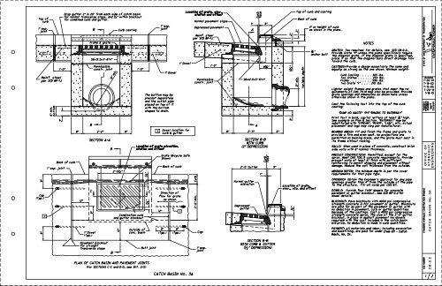
NOTES<br />
GRATES: Two required. For details, see SCD CB-2.2.<br />
Provide Grate "V" unless the plans specifically require<br />
the diagonal grate. If the diagonal grate is specified,<br />
place it so that the diagonal bars direct drainage flow<br />
toward the curb.<br />
CASTINGS: Provide a design essentially the same and<br />
equally as strong as the one shown. Minimum weight:<br />
Curb Casting . . . . . 305 lbs.<br />
Two Grates . . . . . . 254 lbs.<br />
Frame . . . . . . . . . 590 lbs.<br />
Two Grate "V" . . . . 210 lbs.<br />
Lighter weight frames and grates that meet the re-<br />
quirements of CMS 711.14 may also be provided. Provide<br />
grate openings and dimensions as shown here unless<br />
otherwise shown in the plans.<br />
Cast the following text into the top of the curb<br />
casting:<br />
"DUMP NO WASTE" and "DRAINS TO WATERWAY"<br />
Print text in bold, capital letters at least " high.<br />
See example on Plan & Section. "WATERWAY" may be<br />
substituted with "STREAM", "RIVER", "LAKE", etc. Actual<br />
placement and logo may vary per manufacturer.<br />
BEARING AREAS: Fit and finish the frame and grate to<br />
provide a firm and even seat. <strong>No</strong> projections are<br />
permitted on bearing areas, and the grate must seat in<br />
its frame without rocking.<br />
WALLS: When used in place of concrete, construct brick<br />
side walls with 8" nominal thickness.<br />
PRECAST CONSTRUCTION: Permitted, except for the<br />
apron. Meet CMS 706.13 concrete requirements. Provide<br />
precast walls at least 6" thick with sufficient<br />
reinforcing to permit shipping and placement without<br />
damage. Reduce the wall thickness from the outside.<br />
MINIMUM DEPTH: The minimum depth is per the cover<br />
requirements for that pipe type.<br />
OPENINGS: Obtain the Engineer’s approval for any pipe<br />
openings greater than 4" from the outside of the pipe<br />
to the structure. Fill all voids per CMS 611.<br />
DOWELS: Furnish four 1"x18" dowels for concrete<br />
pavement or gutter blockout. See SCD BP-2.2 for<br />
dowel details.<br />
BLOCKOUT: Pave blockouts with 4000 psi compressive<br />
strength concrete in PCC pavement or gutter. Blockouts<br />
are paid for as part of the pavement or gutter with<br />
no deduction in pavement, curb or gutter quantities<br />
because of the castings. Cast a 4000 psi compressive<br />
strength concrete apron, the size of the 2’-0" gutter<br />
blockout, in place in asphalt pavement (no dowels<br />
required) with the cost included in the catch basin<br />
bid price. <strong>No</strong> deduction is made in curb quantities.<br />
PAYMENT: All materials and labor, including excavation<br />
and backfilling, are paid for under Item 611 - Catch<br />
Basin, <strong>No</strong>. <strong>3A</strong>.<br />
STATE OF OHIO DEPARTMENT OF TRANSPORTATION<br />
SCD NUMBER<br />
REVISIONS<br />
7-20-01<br />
7-19-02<br />
7-15-05<br />
ROADWAY<br />
HYDRAULIC<br />
ENGINEER<br />
O FFICE O F<br />
STANDARD HYDRAULIC CONSTRUCTION DRAWING<br />
C A TC H BA SIN <strong>No</strong>. <strong>3A</strong><br />
C B-2.2<br />
1 2<br />
STATE HYDRAULIC ENGINEER<br />
7-20-12<br />
1-18-13<br />
Cozzoli<br />
Matt<br />
ENGINEERING<br />
HY D RA ULIC
5 "<br />
7 "<br />
1’-10 " 1 "<br />
"<br />
"<br />
6"<br />
(Typ.)<br />
4" (Typ.)<br />
2’-1"<br />
3’-2"<br />
PLAN<br />
2’-6"<br />
2’-1"<br />
BACK VIEW<br />
" (Typ.) 2’-6"<br />
1" (Typ.)<br />
1" rad. (Typ.)<br />
3’-2"<br />
FRAME<br />
FRONT VIEW<br />
1" (Typ.)<br />
6" (Typ.)<br />
3" (Typ.)<br />
" (Typ.)<br />
1" rad.<br />
(Typ.)<br />
3" (Typ.)<br />
" rad.<br />
(Typ.)<br />
3" (Typ.)<br />
4" (Typ.)<br />
2"<br />
1’-3"<br />
9 " 5 "<br />
1"<br />
2"<br />
1" (Typ.) 1" (Typ.)<br />
2’-5"<br />
Grate size<br />
SECTION C-C<br />
DIAGONAL GRATE<br />
(See Sht. 1/2)<br />
SECTION D-D<br />
2’-5" x 1’-4" x 2"<br />
DUMP NO WASTE DRAINS TO WATERWAY<br />
Finished<br />
FRONT VIEW<br />
Finished<br />
5<br />
CURB CASTING CURB CASTING<br />
60<br />
7 "<br />
SECTION Y-Y<br />
(See Sht. 1/2.) Direction of flow for<br />
grate as shown<br />
"<br />
1"<br />
3" (Typ.) 1’-6" (Typ.)<br />
3"<br />
6"<br />
1"<br />
bolt hole<br />
"<br />
3’-6"<br />
2"<br />
"<br />
3" rad.<br />
"<br />
"<br />
" radii<br />
all bar edges<br />
Y Y<br />
PLAN END VIEW FRAME<br />
6" 2’-6"<br />
6"<br />
1" rad.<br />
(Typ.)<br />
3’-6"<br />
"<br />
"<br />
"<br />
6"<br />
1’-6" (Typ.) 3" (Typ.)<br />
rad.<br />
1" rad.<br />
1" rad.<br />
" rad.<br />
"<br />
2" rad.<br />
1" rad.<br />
(internal)<br />
2"<br />
"<br />
4"<br />
2"<br />
1’-4 "<br />
"<br />
1 "<br />
9"<br />
"<br />
1"<br />
rad.<br />
"<br />
1"<br />
2"<br />
END VIEW<br />
10 bars @ 2" "<br />
1" rad.<br />
2’-0"<br />
5"<br />
2’-5"<br />
PLAN<br />
GRATE "V"<br />
1’-6 "<br />
1’-5"<br />
1’-2 "<br />
6"<br />
2"<br />
"<br />
3"<br />
1"<br />
1 "<br />
1"<br />
1" rad.<br />
1"<br />
" rad.<br />
4"<br />
2" (Typ.)<br />
5 "<br />
1"<br />
1 " 1 "<br />
bolt hole<br />
9" rad.<br />
STATE OF OHIO DEPARTMENT OF TRANSPORTATION<br />
SCD NUMBER<br />
REVISIONS<br />
7-20-01<br />
7-19-02<br />
7-15-05<br />
ROADWAY<br />
HYDRAULIC<br />
ENGINEER<br />
STANDARD HYDRAULIC CONSTRUCTION DRAWING<br />
C A TC H BA SIN <strong>No</strong>. <strong>3A</strong><br />
C B-2.2<br />
2 2<br />
STATE HYDRAULIC ENGINEER<br />
7-20-12<br />
1-18-13<br />
O FFICE O F<br />
Cozzoli<br />
Matt<br />
ENGINEERING<br />
HY D RA ULIC