MASTERCLAD™ Medium Voltage Metal-clad Switchgear with Type ...
MASTERCLAD™ Medium Voltage Metal-clad Switchgear with Type ...
MASTERCLAD™ Medium Voltage Metal-clad Switchgear with Type ...

You also want an ePaper? Increase the reach of your titles
YUMPU automatically turns print PDFs into web optimized ePapers that Google loves.
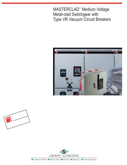
MASTERCLAD <strong>Medium</strong> <strong>Voltage</strong><br />
<strong>Metal</strong>-<strong>clad</strong> <strong>Switchgear</strong> <strong>with</strong><br />
<strong>Type</strong> VR Vacuum Circuit Breakers
M A S T E R C L A D V A C U U M<br />
M E T A L - C L A D S W I T C H G E A R<br />
As a leading<br />
2<br />
manufacturer of<br />
electrical distribu-<br />
tion equipment for over<br />
100 years, Groupe<br />
Schneider has long had a<br />
reputation for quality,<br />
service and technical<br />
innovation. Today, as a<br />
major switchgear manu-<br />
facturer in the<br />
international market-<br />
place, Groupe Schneider<br />
continues to lead the<br />
industry. Along <strong>with</strong> high-<br />
quality equipment, we<br />
offer an engineering and<br />
support staff that is con-<br />
sidered the best in the<br />
industry.
MASTERCLAD<br />
switchgear<br />
components include<br />
available state-ofthe-art<br />
electronics<br />
like POWERLOGIC<br />
power monitoring<br />
and control systems,<br />
SEPAM digital microprocessor-based<br />
protective relays and<br />
SY-MAX PLC-based<br />
automatic transfer<br />
systems.<br />
The Reliability of a Quality Design<br />
The quality of Federal Pioneer MASTERCLAD medium<br />
voltage metal-<strong>clad</strong> switchgear stems from a design and<br />
manufacturing process that focuses on long-term<br />
switchgear performance <strong>with</strong> the highest degree of reliability.<br />
Reliable performance and safety is enhanced by the rugged<br />
construction of MASTERCLAD switchgear. Each switchgear<br />
assembly consists of individually grounded, compartmental-<br />
ized steel structures (<strong>with</strong> 11-gauge barriers between vertical<br />
sections and major parts of each primary circuit) to protect<br />
operating personnel.<br />
Based on specific customer application needs, Federal Pioneer<br />
engineers and technicians select the appropriate standard<br />
sections and bus configurations, <strong>with</strong> the ability to<br />
customize where needed. After the specified circuit breakers,<br />
instrument and control power transformers, relays, meters<br />
and other components are selected and approved, all are<br />
factory-assembled, wired and tested as a complete<br />
assembly. This testing is performed to insure reliability<br />
by energizing the control circuits and verifying the specified<br />
sequence of operation for each metal-<strong>clad</strong> switchgear<br />
project along <strong>with</strong> applicable ANSI, CSA, EEMAC and IEEE<br />
Production Tests.<br />
3
M A S T E R C L A D V A C U U M<br />
M E T A L - C L A D S W I T C H G E A R<br />
MASTERCLAD Vacuum<br />
<strong>Metal</strong>-<strong>clad</strong> <strong>Switchgear</strong><br />
Ratings:<br />
■ 4.76-15 kV<br />
(to 13.8 kV nominal)<br />
■ 1200-3000 Amperes<br />
■ 250-1000 MVA<br />
Interrupting Class<br />
■ 60 and 95 kV BIL<br />
■ Indoor and Outdoor<br />
Enclosures<br />
Standard Features:<br />
<strong>Metal</strong>-<strong>clad</strong> switchgear as<br />
defined by ANSI C37.20.2<br />
includes:<br />
■ Removable (Drawout)<br />
Circuit Breaker<br />
■ Fully Compartmented<br />
Construction<br />
■ Grounded <strong>Metal</strong> Barriers<br />
Enclose all Live Parts<br />
■ Automatic Shutters<br />
■ Insulated Bus<br />
■ Mechanical Interlocks<br />
■ Disconnect <strong>Type</strong> <strong>Voltage</strong><br />
Transformers—CPT<br />
and VTs<br />
■ Grounded Circuit Breaker<br />
Truck in and between<br />
Test/Disconnected and<br />
Connected Positions<br />
■ Low <strong>Voltage</strong> Instrument/<br />
Control Compartment<br />
Isolated from Primary<br />
<strong>Voltage</strong> areas<br />
Federal Pioneer <strong>Metal</strong>-<strong>clad</strong> <strong>Switchgear</strong> is designed and<br />
manufactured in facilities that are Registered to ISO 9001.<br />
4<br />
Applications<br />
MASTERCLAD medium<br />
voltage switchgear is<br />
used in a wide variety of<br />
switching, control and<br />
protective applications<br />
including electric utility<br />
generation and distribution<br />
systems, industrial plants,<br />
commercial buildings,<br />
hospitals, municipal pumping<br />
stations, wastewater<br />
treatment plants, transportation<br />
systems, and pipeline<br />
stations. Transformers,<br />
motors, generators, capacitors,<br />
distribution lines, and<br />
feeder circuits are protected<br />
by this class of switchgear.<br />
Significantly, most of the<br />
MASTERCLAD switchgear<br />
specified for these applications<br />
is relied upon to<br />
provide the critical main<br />
service entrance protection<br />
and controls.<br />
Standardization<br />
Standardization of the design<br />
incorporates a series of<br />
basic modular units, control<br />
packages, and instrumentation.<br />
For most switchgear<br />
ratings, circuit configurations<br />
and functions, one basic size<br />
unit is used. These features<br />
provide application flexibility,<br />
versatility, efficiency and<br />
economy in minimizing<br />
engineering time to plan and<br />
lay out the switchgear.<br />
Front view <strong>with</strong> lower<br />
breaker installed.
Features and Benefits<br />
Long Life/Minimum<br />
Maintenance<br />
Reliability is the main priority.<br />
The VR vacuum circuit<br />
breakers are designed for<br />
long life. The interrupter’s<br />
copper-chromium contacts,<br />
hermetically sealed for life in<br />
a vacuum, are protected<br />
from external atmospheric<br />
influences. Dust, moisture,<br />
and all other possible contaminants<br />
are sealed out. This<br />
state-of-the-art vacuum<br />
interrupter design is capable of<br />
20-100 full fault interruptions<br />
(varies by rating).<br />
The high dielectric strength of<br />
the vacuum environment<br />
allows a very short clearing<br />
time during fault interruption<br />
to limit the energy dissipated<br />
into the arc. Total fault<br />
clearing time is less than<br />
3 cycles and contact travel<br />
is only 3/8 to 1/2 inch,<br />
depending on the ratings of<br />
the circuit breaker. The short<br />
stroke produces less<br />
mechanical shock to the<br />
operating mechanism.<br />
For evaluation of wear on<br />
the main contacts over the<br />
life of the circuit breaker,<br />
contact erosion indication is<br />
provided on each interrupter<br />
pole assembly.<br />
Together <strong>with</strong> a total<br />
commitment to quality, these<br />
features provide long life <strong>with</strong><br />
high reliability.<br />
Safety Barriers<br />
and Interlocks<br />
Full compartmentalization<br />
is supplied <strong>with</strong> primary functions<br />
separated by grounded<br />
metal barriers. All bussing is<br />
insulated and live parts are<br />
not exposed.<br />
Safety interlocks work <strong>with</strong><br />
the circuit breaker racking<br />
system. These protective<br />
features furnish integrity<br />
to the equipment and<br />
provide safety for operating<br />
personnel.<br />
Floor Space Economy and<br />
Application Flexibility<br />
The two tier configuration<br />
permits feeder circuit<br />
breakers to be stacked two<br />
high to save valuable floor<br />
space, or stacked one high<br />
combined <strong>with</strong> auxiliary units<br />
for the ultimate in application<br />
flexibility.<br />
Convenient Handling<br />
The VR circuit breaker is a<br />
horizontal drawout type<br />
designed to provide long life,<br />
reduced maintenance and<br />
ease of handling. The circuit<br />
breaker truck has wheels for<br />
easy movement into a lower<br />
cell (indoor switchgear) <strong>with</strong>out<br />
use of any lifting device.<br />
A lifting truck is provided for<br />
installation of a circuit breaker<br />
into an upper cell. Typical<br />
circuit breaker weight is 159-<br />
218 kg (350-480 lbs).<br />
Comprehensive<br />
Test Program<br />
Federal Pioneer development<br />
engineers have<br />
performed a comprehensive<br />
design testing program.<br />
The switchgear and circuit<br />
breakers are designed and<br />
tested in accordance <strong>with</strong> all<br />
applicable ANSI and CSA<br />
Standards. The switchgear<br />
and circuit breakers meet<br />
the requirements of ANSI,<br />
CSA, EEMAC and IEEE,<br />
and generally exceed IEC<br />
standards.<br />
Rear view/termination<br />
compartment <strong>with</strong><br />
incoming line and<br />
load bus runbacks.<br />
5
P R I N C I P A L M A S T E R C L A D <br />
C O M P O N E N T S<br />
Hinged Front Door<br />
Relays and metering<br />
instruments are mounted on<br />
the doors in standardized<br />
arrangements to satisfy<br />
customer requirements.<br />
Each circuit breaker<br />
compartment door provides<br />
a racking access port to allow<br />
moving the circuit breaker to<br />
or from the connected<br />
position <strong>with</strong> the door closed.<br />
(Option for single full-height<br />
door <strong>with</strong> “one-high”<br />
construction.)<br />
Horizontal Drawout<br />
Circuit Breaker<br />
VR vacuum circuit breakers<br />
utilize the horizontal<br />
drawout design. Test/<br />
disconnected and connected<br />
positions are provided.<br />
Control Power<br />
Transformers<br />
Control power transformers<br />
rated up to 15 kVA are<br />
drawer mounted and can be<br />
completely <strong>with</strong>drawn from<br />
the front of the switchgear<br />
for ease of maintenance. A<br />
secondary circuit breaker<br />
mechanical interlock is<br />
provided and must be<br />
opened before the transformer<br />
can be <strong>with</strong>drawn for<br />
access to primary fuses.<br />
<strong>Voltage</strong> Transformers<br />
Front accessible, drawer<br />
mounted voltage transformers<br />
can be completely<br />
<strong>with</strong>drawn on extension rails.<br />
For operator safety, the<br />
voltage transformers are<br />
disconnected and grounded<br />
during movement to the<br />
<strong>with</strong>drawn position.<br />
6<br />
Control Power<br />
Transformers<br />
<strong>Voltage</strong><br />
Transformers<br />
Hinged<br />
Front Door<br />
Horizontal<br />
Drawout<br />
Circuit<br />
Breaker<br />
Federal Pioneer <strong>Metal</strong>-<strong>clad</strong> <strong>Switchgear</strong> is designed and<br />
manufactured in facilities that are Registered to ISO 9001.<br />
Cell-Mounted<br />
Racking<br />
Mechanism<br />
Racking System<br />
The high quality gear-driven<br />
racking mechanism is<br />
center-mounted on the cell<br />
floor, providing balanced<br />
movement of the circuitbreaker<br />
between cell<br />
positions. The racking<br />
system is coordinated <strong>with</strong><br />
safety interlocks to prevent<br />
movement of the circuit<br />
breaker unless the main<br />
contacts are in the open<br />
position.<br />
Cell Release/<br />
Manual Trip<br />
Handle<br />
Racking access<br />
port <strong>with</strong> front<br />
door closed.
Cable Space<br />
Top or bottom power cable<br />
entry space is provided. The<br />
quantity of cable termination<br />
devices and space for surge<br />
arresters vary <strong>with</strong> the ratings<br />
of circuit breakers selected<br />
for each vertical section.<br />
Compartment Barriers<br />
Grounded metal barriers<br />
separate the main<br />
compartments — circuit<br />
breaker, main bus, cable,<br />
instrument/ relay (low voltage<br />
area), and auxiliary (VT<br />
and/or CPT).<br />
Main Bus and Insulation<br />
Main bus and runbacks<br />
are insulated <strong>with</strong> a trackresistant,<br />
flame retardant<br />
epoxy coating by the<br />
fluidized bed process. Bus<br />
support standoff insulators<br />
are resin based. Bus joints<br />
are insulated by flexible<br />
resin boots. Access covers<br />
are provided for main bus<br />
inspection from front and<br />
rear.<br />
Main Bus Barriers<br />
Main bus barriers between<br />
bays are track-resistant,<br />
flame retardant glass<br />
polyester.<br />
Automatic Shutters<br />
When the circuit breaker is<br />
<strong>with</strong>drawn from the<br />
connected position, the<br />
racking mechanism linkage<br />
positively rotates the<br />
grounded metal shutters into<br />
a position which covers the<br />
energized components.<br />
Frame and Housing<br />
Precision-formed steel<br />
frames and inner panels,<br />
painted by the superior<br />
TGIC Polyester Powder<br />
Coating Process, provide<br />
a strong rust-resistant<br />
structure <strong>with</strong> rigid alignment<br />
of components.<br />
Cable Space<br />
Compartment<br />
Barriers<br />
Insulated<br />
Main Bus<br />
Main Bus<br />
Barriers<br />
Ground Bus<br />
Side view <strong>with</strong> side<br />
cover sheet removed.<br />
Automatic<br />
Shutters<br />
Frame and<br />
Housing<br />
Inter-bay<br />
Control Wire<br />
Areas<br />
7
M A S T E R C L A D <br />
C I R C U I T B R E A K E R<br />
C O M P A R T M E N T F E A T U R E S<br />
Control Wiring<br />
Cell Switch—<br />
T-O-C<br />
Auxiliary<br />
Switch—M-O-C<br />
Auxiliary<br />
Switch<br />
Actuator<br />
Insulating<br />
Bushing Around<br />
Stationary Main<br />
Bus Contact<br />
Current<br />
Transformers<br />
Racking<br />
Trip/Spring<br />
Discharge<br />
Interlock<br />
Ground Bus<br />
Circuit Breaker<br />
Rating Block<br />
Circuit Breaker<br />
Removal<br />
Latch Cam<br />
Shutter<br />
Locking<br />
Provisions—<br />
Padlock/Key<br />
Interlock<br />
Circuit Breaker<br />
Alignment<br />
Rails<br />
8<br />
Circuit Breaker Compartment Floor<br />
Details (Highlighted View)<br />
Federal Pioneer <strong>Metal</strong>-<strong>clad</strong> <strong>Switchgear</strong> is designed and<br />
manufactured in facilities that are Registered to ISO 9001.<br />
Circuit Breaker<br />
Position<br />
Indicator<br />
Secondary<br />
control plug<br />
operating<br />
handle used<br />
for test<br />
position only.<br />
Secondary<br />
Control<br />
Receptacle
Control Wiring<br />
All secondary/control wiring,<br />
including terminal blocks, CT<br />
shorting blocks, and other<br />
devices are located in the<br />
instrument compartment at<br />
the front of each breaker<br />
section, isolated from the<br />
primary voltage areas. Each<br />
section has provisions for<br />
control wiring entry from top<br />
or bottom.<br />
Cell Switch—T-O-C<br />
(Optional) Stationary-mounted<br />
switch, 6 or 10 contacts,<br />
provides electrical indication<br />
of the position of the circuit<br />
breaker in the cell —<br />
connected position or test/<br />
disconnected position.<br />
Auxiliary Switch—M-O-C<br />
(Optional) Stationary-mounted<br />
switch, 6 or 10 contacts,<br />
maintains the same position<br />
as the circuit breakermounted<br />
auxiliary switch —<br />
indicating if the circuit<br />
breaker is open or closed.<br />
Current Transformers<br />
(Mounted behind shutters)<br />
Bushing type current<br />
transformers are front<br />
accessible—located behind<br />
the shutters (shown in open<br />
position*, in photo at left) and<br />
mounted on the primary<br />
insulating bushings. Space<br />
will permit one or two current<br />
transformers on both sides of<br />
each circuit breaker — up to<br />
four total <strong>with</strong> ANSI standard<br />
relay accuracy class rating;<br />
two maximum <strong>with</strong> higher<br />
relay accuracies.<br />
Secondary Control<br />
Receptacle<br />
Self-aligning receptacle<br />
automatically engages the<br />
control plug when circuit<br />
breaker is racked to the<br />
connected position.<br />
Auxiliary Switch<br />
Actuator<br />
Operates M-O-C Auxiliary<br />
Switch when the circuit<br />
breaker is in the connected<br />
position and in the test<br />
position (unless otherwise<br />
specified).<br />
Circuit Breaker<br />
Alignment Rails<br />
The circuit breaker cell has<br />
slotted alignment rails which<br />
capture the circuit breaker<br />
rail rollers on each side of the<br />
circuit breaker to provide<br />
assurance of circuit breaker<br />
alignment <strong>with</strong> the cell. Note<br />
that the rail rollers are sidemounted<br />
and different from<br />
the wheels on the circuit<br />
breaker truck.<br />
Circuit Breaker Removal<br />
Latch Cam<br />
Prevents removal of circuit<br />
breaker until handle at bottom<br />
front of circuit breaker is<br />
pulled by the operator.<br />
Primary Insulating<br />
Bushings/Stationary Main<br />
Contacts<br />
(Shown <strong>with</strong> current<br />
transformers)<br />
Standard glass polyester<br />
insulating bushings are used<br />
to support the primary<br />
stationary disconnect<br />
main contacts. The same<br />
bushings provide insulated<br />
mounting provisions for the<br />
current transformers.<br />
*Note: Shown <strong>with</strong> shutter barrier removed and shutters in the open position<br />
for illustrative purposes only. If access to current transformers is required,<br />
the switchgear must be de-energized before the shutters are moved to the<br />
open position.<br />
Spring Discharge<br />
Interlocks<br />
Both opening and closing<br />
springs are automatically<br />
discharged when circuit<br />
breaker is removed from the<br />
compartment. Racking arm<br />
operates linkage on bottom<br />
of circuit breaker.<br />
Circuit Breaker<br />
Rating Block<br />
Prevents insertion of a<br />
circuit breaker <strong>with</strong> lower<br />
rating, either MVA or<br />
continuous ampacity, than<br />
the compartment is designed<br />
to accept.<br />
Circuit Breaker<br />
Position Indicator<br />
The circuit breaker position,<br />
either “connected” or<br />
“test/disconnected,” is shown<br />
by the rotation of a colored<br />
indicator wheel driven by the<br />
racking mechanism and<br />
clearly visible <strong>with</strong> the cell<br />
front door either open or<br />
closed.<br />
Shutter Locking<br />
Provisions<br />
The safety shutters may<br />
be locked closed by<br />
padlocking (1 or 2) or by key<br />
interlock to prevent installation<br />
of a circuit breaker when<br />
required by customer maintenance<br />
procedures.<br />
Racking Trip<br />
Interlock<br />
Maintains circuit breaker trip<br />
position during racking<br />
between test and connected<br />
positions. Racking arm<br />
operates linkage on bottom<br />
of circuit breaker.<br />
9
M A S T E R C L A D T Y P E V R<br />
V A C U U M C I R C U I T B R E A K E R<br />
The Square D brand VR<br />
circuit breaker <strong>with</strong> the <strong>Type</strong><br />
RI advanced design motorcharged<br />
stored energy<br />
mechanism is a model of<br />
reliability <strong>with</strong> simplicity —<br />
virtually maintenance free.<br />
With an operating life<br />
exceeding the ANSI test<br />
requirements, the RI<br />
mechanism <strong>with</strong><br />
synchronizing crossbar<br />
is electrically and<br />
mechanically trip-free.<br />
An integral handle (nonremovable)<br />
is provided<br />
for manual charging and<br />
slow-closing during testing.<br />
10<br />
The VR is<br />
completely<br />
tested and<br />
certified to<br />
all applicable<br />
ANSI circuit<br />
breaker<br />
standards.<br />
Rail rollers<br />
(Both Sides)<br />
Federal Pioneer <strong>Metal</strong>-<strong>clad</strong> <strong>Switchgear</strong> is designed and<br />
manufactured in facilities that are Registered to ISO 9001.<br />
Manual charging<br />
handle is<br />
permanently<br />
mounted on<br />
the <strong>Type</strong> RI<br />
operating<br />
mechanism.
The vacuum interrupters<br />
of the VR circuit breaker are<br />
mounted in high-strength,<br />
moulded glass-reinforced<br />
polyester insulation/support<br />
housings. The moulded<br />
housings position the bus<br />
runbacks for precise alignment.<br />
The completed pole<br />
units are bolted directly to<br />
the circuit breaker truck.<br />
The inherent rigidity and<br />
mechanical strength of this<br />
circuit breaker design<br />
complement the operating<br />
mechanism, resulting in high<br />
endurance and reliability.<br />
VR circuit<br />
breaker <strong>with</strong><br />
front cover<br />
removed<br />
VR circuit<br />
breaker<br />
rear view<br />
11
M A S T E R C L A D <br />
M E T A L - C L A D S W I T C H G E A R<br />
D I M E N S I O N S / R A T I N G S<br />
One high (main or feeder) arrangement <strong>with</strong> auxiliary<br />
drawout units behind the relay/meter door.<br />
Note: For 3000 A applications, the compartment above<br />
the 3000 A circuit breaker is blank except for relays, control<br />
switches, and other instruments.<br />
Auxiliary section <strong>with</strong> up to four drawout units—<br />
VTs, CPT (to 15 kVA), primary fuse truck for<br />
(rear) fixed-mtd. CPT to 50 kVA-1Ø; 45 kVA-3Ø.<br />
Weights<br />
Section, (less c/b): 909 kg (2000 lbs)<br />
1200 A Circuit Breaker: 164 kg (360 lbs)<br />
2000 A Circuit Breaker: 186 kg (410 lbs)<br />
3000 A Circuit Breaker: 218 kg (480 lbs)<br />
12<br />
36"w Sections <strong>with</strong> Standard Dimensions<br />
Federal Pioneer <strong>Metal</strong>-<strong>clad</strong> <strong>Switchgear</strong> is designed and<br />
manufactured in facilities that are Registered to ISO 9001.<br />
Two high feeder section arrangement—1200/1200A<br />
or 1200/2000A. Top or bottom cable entry.<br />
203<br />
(8.0)<br />
63.5 (2.5)<br />
Top Breaker<br />
Conduit Area<br />
Bottom Breaker<br />
Conduit Area<br />
(6) 19.1 ( .75) Dia.<br />
Mounting Holes<br />
Recommended<br />
102 (4.0) Mounting Channels<br />
(3) Places (Not Included)<br />
Control Conduit Area<br />
(Bottom)<br />
44.5<br />
(1.75)<br />
50.8<br />
(2.0)<br />
Control Conduit Area<br />
(Top)<br />
229 (9.0)<br />
25.4 (1.0)<br />
229 (9.0)<br />
89<br />
(3.5)<br />
89<br />
(3.5)<br />
203 (8.0)<br />
64 (2.5)<br />
22.9 ( .9)<br />
22.9<br />
(9.0)<br />
12.7 ( .5)<br />
737<br />
(29.0)<br />
457<br />
(18.0)<br />
50.8 (2.0)<br />
869<br />
(34.2)<br />
914<br />
(36.0)<br />
22.9<br />
(9.0)<br />
Typical Indoor 1200/2000A<br />
Floor Plan<br />
89<br />
(3.5)<br />
25.4<br />
(1.0)<br />
Door<br />
22.9<br />
( .9)<br />
Do Not Use for Construction. Dimensions are in mm (Inches).<br />
914 (36.0) Rear Aisle<br />
25.4<br />
(1.0)<br />
1080 (42.5)<br />
1168 (46.0)<br />
38.1<br />
(1.5)<br />
2337<br />
(92.0)<br />
<strong>with</strong><br />
Door<br />
1829 (72.0) Front Aisle<br />
(1626 (64.0) Minimum)
Circuit Breaker Ratings Data Chart<br />
Rated<br />
Cont.<br />
Short<br />
Time Close &<br />
Current Max. Min. Low Impulse Max. Nom. Min. Asym- Rating Latch Inter-<br />
Three <strong>Voltage</strong> 60 Hertz <strong>Voltage</strong> Range <strong>Voltage</strong> Freq. 1.2x50µs kV kV kV metrical 3 Sec. Rating rupting<br />
Phase kV– Amps.– kV– Factor kV– kV– kV– Amps.– Amps.– Amps.– Rating Amps.– Amps.– Time<br />
<strong>Type</strong> of Breaker MVA rms rms rms K rms rms Crest ➁<br />
rms ➂<br />
rms rms Factor ➃<br />
rms rms ➄<br />
Insulation Level Interrupting Ratings<br />
Cycles<br />
VR-05025-12 250 4.16 1200 4.76 1.24 3.85 19 60 29,000 33,200 36,000 1.2 36,000 58,000 3<br />
VR-05025-20 250 4.16 2000 4.76 1.24 3.85 19 60 29,000 33,200 36,000 1.2 36,000 58,000 3<br />
VR-05025-30 250 4.16 3000 4.76 1.24 3.85 19 60 29,000 33,200 36,000 1.2 36,000 58,000 3<br />
VR-05035-12 350 4.16 1200 4.76 1.19 4.0 19 60 41,000 46,900 49,000 1.2 49,000 78,000 3<br />
VR-05035-20 350 4.16 2000 4.76 1.19 4.0 19 60 41,000 46,900 49,000 1.2 49,000 78,000 3<br />
VR-05035-30 350 4.16 3000 4.76 1.19 4.0 19 60 41,000 46,900 49,000 1.2 49,000 78,000 3<br />
VR-08050-12 500 7.20 1200 8.25 1.25 6.6 36 95 33,000 37,800 41,000 1.2 41,000 66,000 3<br />
VR-08050-20 500 7.20 2000 8.25 1.25 6.6 36 95 33,000 37,800 41,000 1.2 41,000 66,000 3<br />
VR-08050-30 500 7.20 3000 8.25 1.25 6.6 36 95 33,000 37,800 41,000 1.2 41,000 66,000 3<br />
VR-15050-12 500 13.8 1200 15.0 1.30 11.5 36 95 18,000 19,500 23,000 1.2 23,000 37,000 3<br />
VR-15050-20 500 13.8 2000 15.0 1.30 11.5 36 95 18,000 19,500 23,000 1.2 23,000 37,000 3<br />
VR-15050-30 500 13.8 3000 15.0 1.30 11.5 36 95 18,000 19,500 23,000 1.2 23,000 37,000 3<br />
VR-15075-12 750 13.8 1200 15.0 1.30 11.5 36 95 28,000 30,400 36,000 1.2 36,000 58,000 3<br />
VR-15075-20 750 13.8 2000 15.0 1.30 11.5 36 95 28,000 30,400 36,000 1.2 36,000 58,000 3<br />
VR-15075-30 750 13.8 3000 15.0 1.30 11.5 36 95 28,000 30,400 36,000 1.2 36,000 58,000 3<br />
VR-15100-12 1000 13.8 1200 15.0 1.30 11.5 36 95 37,000 40,200 48,000 1.2 48,000 77,000 3<br />
VR-15100-20 1000 13.8 2000 15.0 1.30 11.5 36 95 37,000 40,200 48,000 1.2 48,000 77,000 3<br />
VR-15100-30 1000 13.8 3000 15.0 1.30 11.5 36 95 37,000 40,200 48,000 1.2 48,000 77,000 3<br />
➀<br />
Nominal Rating Rated <strong>Voltage</strong>s Rated Withstand Amps. – Symmetrical<br />
➀ For interrupting current ratings at<br />
operating voltages other than those<br />
listed, use the following<br />
formula:<br />
Vmax Iop = x IVmax<br />
Vop<br />
The calculated current should not<br />
exceed the maximum interrupting<br />
current rating, Imax:<br />
Imax = K x IVmax<br />
➁ These values apply <strong>with</strong> circuit<br />
breaker in or out of enclosure.<br />
➂ Rated Short Circuit Current<br />
(at rated Max kV).<br />
➃ Rating factor is based on circuit<br />
breaker speed from initiation of<br />
trip signal to contact parting,<br />
allowing for 1/2 cycle relay time.<br />
To obtain the asymmetrical current<br />
interrupting capacity of the circuit<br />
breaker, multiply the symmetrical<br />
current by 1.2.<br />
➄ Close and Latch Rating<br />
(Momentary) Amps rms = (1.6K)<br />
(Rated Short Circuit Current).<br />
Additional Close and Latch Rating in<br />
kA Crest = (2.7K) (Rated Short<br />
Circuit Current).<br />
Circuit Breaker<br />
Identification<br />
VR 05 025 12<br />
Continuous Current Rating<br />
MVA Rating<br />
<strong>Voltage</strong> Rating<br />
Circuit Breaker <strong>Type</strong><br />
13
S U G G E S T E D<br />
S P E C I F I C A T I O N G U I D E<br />
General<br />
The (indoor) (outdoor nonwalk-in)<br />
(outdoor walk-in)<br />
<strong>Metal</strong>-<strong>clad</strong> <strong>Switchgear</strong><br />
described in this specification<br />
is intended for use on a<br />
(2400) (4160) (4800) (6900)<br />
(13800) volt 3-phase (3)<br />
(4) wire (grounded)<br />
(ungrounded) 60 Hertz<br />
system. The switchgear shall<br />
be rated (4160) (7200)<br />
(13800) nominal volts and<br />
have VR horizontal drawout<br />
circuit breakers.<br />
The switchgear and circuit<br />
breakers, individually and as<br />
a unit, shall have a BIL<br />
(impulse) rating of (60)<br />
(95) kV. The momentary<br />
rating of the switchgear bus<br />
shall be equal to the close<br />
and latch rating of the circuit<br />
breakers. The entire<br />
switchgear assembly<br />
including circuit breakers,<br />
meters, relays, etc., shall be<br />
completely factory tested<br />
and the circuit breakers of<br />
like ratings shall be<br />
interchangeable.<br />
Applicable Standards<br />
The switchgear covered by<br />
this specification shall be<br />
designed, tested, and<br />
assembled in accordance<br />
<strong>with</strong> the applicable<br />
standards of ANSI, CSA,<br />
EEMAC and IEEE.<br />
Federal Pioneer <strong>Metal</strong>-<strong>clad</strong> <strong>Switchgear</strong> is designed and<br />
manufactured in facilities that are Registered to ISO 9001.<br />
14<br />
Stationary Structure<br />
The switchgear shall<br />
consist of __ sections<br />
including __ circuit breaker<br />
compartments and __<br />
auxiliary compartments<br />
assembled to form a rigid,<br />
self-supporting, completely<br />
enclosed structure providing<br />
steel barriers between<br />
sections. The sections are<br />
divided by metal barriers into<br />
the following separate<br />
compartments: circuit<br />
breaker, instrument, main<br />
bus, auxiliary device, and<br />
cable. Each section may<br />
have up to two circuit<br />
breaker compartments.<br />
Circuit Breaker<br />
Compartment<br />
Each circuit breaker<br />
compartment shall be<br />
designed to house a VR<br />
horizontal drawout (4160)<br />
(7200) (13800) volt vacuum<br />
circuit breaker. The<br />
stationary primary<br />
disconnecting contacts are to<br />
be silver-plated copper and<br />
mounted <strong>with</strong>in glass polyester<br />
support bushings. The<br />
movable contacts and<br />
springs shall be mounted<br />
on the circuit breaker<br />
element for ease of<br />
inspection/maintenance.<br />
Entrance to the stationary<br />
primary disconnecting contacts<br />
shall be automatically<br />
covered by metal shutters<br />
when the circuit breaker is<br />
<strong>with</strong>drawn to the test or<br />
disconnected positions or<br />
removed from the circuit<br />
breaker compartment.<br />
The metal shutters shall<br />
be operated by direct<br />
mechanical linkage to<br />
the floor-mounted racking<br />
mechanism. The ground bus<br />
shall be extended into the<br />
circuit breaker compartment<br />
to automatically ground the<br />
circuit breaker frame when<br />
in the test and connected<br />
positions <strong>with</strong> high-current<br />
spring type grounding contacts<br />
located on the circuit<br />
breaker chassis. Slotted<br />
guide rails for positioning the<br />
circuit breaker and all other<br />
necessary hardware are to<br />
be an integral part of the circuit<br />
breaker compartment.<br />
The circuit breaker rail rollers<br />
shall be held captive on both<br />
top and bottom by the slotted<br />
guide rails to provide<br />
assurance of circuit breaker<br />
alignment <strong>with</strong> the cell, while<br />
preventing vertical movement<br />
of the circuit breaker<br />
truck during normal operation<br />
and under short circuit conditions.<br />
A circuit breaker<br />
position indicator (“connected”<br />
or “test/disconnected”)<br />
shall be driven by the racking<br />
mechanism and be<br />
visible <strong>with</strong> the front door<br />
either open or closed.<br />
Blocking devices shall interlock<br />
circuit breaker frame<br />
sizes to prevent installation<br />
of a lower ampere rating or<br />
interrupting capacity<br />
element into a compartment<br />
designed for one of a higher<br />
rating. It shall be possible<br />
<strong>with</strong> indoor or outdoor walkin<br />
switchgear to install a<br />
circuit breaker into a bottom<br />
compartment <strong>with</strong>out use of<br />
a transport truck or lift<br />
device.<br />
Cable Compartment<br />
(Clamp type cable lugs)<br />
(Potheads) (Cable<br />
terminators) shall be<br />
furnished as shown on<br />
plans. The copper ground<br />
bus shall extend through this<br />
compartment for the full<br />
length of the switchgear.<br />
Main Bus Compartment<br />
The main bus is to be rated<br />
(1200) (2000) (3000) amperes<br />
and be fully insulated for its<br />
entire length <strong>with</strong> an epoxy<br />
coating by the fluidized bed<br />
process. The conductors are<br />
to be copper <strong>with</strong> silverplated<br />
joints and be of a<br />
bolted (not welded) design.<br />
Access to this compartment<br />
is gained from the front or<br />
rear of the structure by<br />
removing a steel barrier. Bus<br />
support standoff insulators<br />
shall be resin based. Bus<br />
joints shall be insulated <strong>with</strong><br />
flexible resin boots.
Doors and Panels —<br />
Indoor and Outdoor<br />
Relays, meters, control<br />
switches, etc., shall be<br />
mounted on a formed fronthinged<br />
panel for each circuit<br />
breaker compartment. In<br />
addition, outdoor sections,<br />
EEMAC 3R non-walk-in,<br />
have full-height weatherproof<br />
front door <strong>with</strong> 3-point latch.<br />
Indoor sections to be<br />
furnished <strong>with</strong> two screwremovable<br />
rear panels.<br />
Outdoor sections to be<br />
furnished <strong>with</strong> full-height<br />
rear-hinged panels.<br />
Circuit Breakers<br />
The VR circuit breakers shall<br />
be rated (4160) (7200)<br />
(13800) nominal volts, 60<br />
Hertz, (1200) (2000) (3000)<br />
amperes and an interrupting<br />
class rating of (250) (350)<br />
(500) (750) (1000) MVA <strong>with</strong><br />
one vacuum interrupter per<br />
phase. Circuit breakers of<br />
equal rating shall be<br />
completely interchangeable.<br />
The circuit breaker shall be<br />
operated by means of a<br />
stored energy mechanism<br />
which is normally charged by<br />
a universal motor, but can<br />
also be charged by the<br />
integral handle for manual<br />
emergency closing or<br />
testing. The closing speed of<br />
the moving contacts is to be<br />
independent of both the<br />
control voltage and the<br />
operator. Provide a full front<br />
shield on the circuit breaker.<br />
Positive contact secondary<br />
disconnect shall be through<br />
automatic self-aligning, selfengaging<br />
type plug and<br />
contact arrangement.<br />
Provision shall be made for<br />
control power plug to be<br />
manually connected in test<br />
position. A minimum of 4<br />
auxiliary contacts (2a, 2b)<br />
shall be provided for external<br />
use. Provisions shall be<br />
made for (6) (10) additional<br />
cell-mounted auxiliary<br />
contacts (M-O-C type) (and)<br />
(T-O-C type) for external use.<br />
An interlocking system shall<br />
be provided to make it<br />
impossible to rack a closed<br />
circuit breaker to or from any<br />
position. An additional interlock<br />
shall automatically<br />
discharge the stored-energy<br />
operating mechanism<br />
springs upon removal of<br />
the circuit breaker from the<br />
compartment.<br />
The circuit breaker control<br />
voltage shall be:<br />
(48) (125) (250) volts DC<br />
(120) (230) volts AC<br />
Instrument Transformers<br />
Current transformers: each<br />
circuit breaker compartment<br />
shall have provision for frontaccessible<br />
mounting of up to<br />
four current transformers per<br />
phase, two on bus side and<br />
two on cable side of circuit<br />
breaker. The current transformer<br />
assembly shall be<br />
insulated for the full voltage<br />
rating of the switchgear.<br />
Relaying and metering accuracy<br />
shall conform to CSA<br />
standards.<br />
<strong>Voltage</strong> transformers are<br />
drawout mounted <strong>with</strong><br />
primary current-limiting fuses<br />
and shall have ratio as indicated.<br />
The transformers shall<br />
have mechanical rating<br />
equal to the momentary<br />
rating of the circuit breakers<br />
and shall have metering<br />
accuracy per CSA standards.<br />
Control Wiring<br />
The switchgear shall be<br />
wired <strong>with</strong> <strong>Type</strong> SIS #14<br />
AWG, except #12 AWG*<br />
for current transformers<br />
wiring. The switchgear shall<br />
be provided <strong>with</strong> terminal<br />
blocks for out-going control<br />
connections.<br />
Standard Finish<br />
After pretreatment to form<br />
a primer coating of zinc<br />
phosphate on the metal,<br />
finish coating shall be an<br />
electrostatically applied TGIC<br />
polyester powder paint. The<br />
process shall be designed<br />
to <strong>with</strong>stand at least 2500<br />
hours of salt spray as tested<br />
per ASTM B-117 and ASTM<br />
D-1654. <strong>Switchgear</strong> finish**<br />
to be light gray ANSI #61.<br />
Accessories<br />
Standard accessories<br />
shall be furnished <strong>with</strong><br />
the switchgear, including:<br />
Manual charging/slow close<br />
handle (on front of each<br />
circuit breaker.)<br />
Manual racking crank<br />
handle (one per lineup.)<br />
Optional Accessories:<br />
Test cabinet, test cable <strong>with</strong><br />
jack and plug, 5th wheel,<br />
circuit breaker lift truck***,<br />
manual ground and test unit<br />
(MGTU), automatic/<br />
electrically-operated ground<br />
and test unit (AGTU), and<br />
remote racking motor.<br />
For further information<br />
about Federal Pioneer<br />
MASTERCLAD <strong>Switchgear</strong><br />
<strong>with</strong> Vacuum Circuit<br />
Breakers, contact your<br />
nearby Groupe Schneider<br />
sales office. They are<br />
conveniently located in over<br />
680 cities throughout the<br />
world and in all major cities<br />
across Canada.<br />
* #10 AWG also available for current transformer wiring at additional cost.<br />
** Optional exterior colours also available at additional cost.<br />
*** The lift truck is provided for indoor and outdoor walk-in switchgear <strong>with</strong> upper<br />
compartment circuit breaker cells. The lift truck is also provided for all outdoor<br />
non-walk-in switchgear to install circuit breakers over the base channels.<br />
15
Federal Pioneer and are Registered<br />
Trademarks of Schneider Canada Inc.<br />
MASTERCLAD is a Trademark of Federal<br />
Pioneer.<br />
Schneider Electric Schneider Electric<br />
F6055BR9801EP R0 (replaces C-3-700)<br />
19 Waterman Avenue<br />
Toronto, Ontario M4B 1Y2<br />
www.schneider.ca<br />
Tel: (416) 752-8020<br />
Fax: (416) 752-6232<br />
© 1998 Schneider Canada, All Rights Reserved<br />
August, 1998