LT1083/LT1084/LT1085 - Linear Technology
LT1083/LT1084/LT1085 - Linear Technology
LT1083/LT1084/LT1085 - Linear Technology

Create successful ePaper yourself
Turn your PDF publications into a flip-book with our unique Google optimized e-Paper software.
<strong>LT1083</strong>/<strong>LT1084</strong>/<strong>LT1085</strong><br />
APPLICATIONS INFORMATION<br />
Normally, capacitor values on the order of 100μF are used<br />
in the output of many regulators to ensure good transient<br />
response with heavy load current changes. Output capacitance<br />
can be increased without limit and larger values of<br />
output capacitor further improve stability and transient<br />
response of the <strong>LT1083</strong> regulators.<br />
Another possible stability problem that can occur in monolithic<br />
IC regulators is current limit oscillations. These can<br />
occur because, in current limit, the safe area protection<br />
exhibits a negative impedance. The safe area protection<br />
decreases the current limit as the input-to-output voltage<br />
increases. That is the equivalent of having a negative<br />
resistance since increasing voltage causes current to<br />
decrease. Negative resistance during current limit is not<br />
unique to the <strong>LT1083</strong> series and has been present on all<br />
power IC regulators. The value of the negative resistance<br />
is a function of how fast the current limit is folded back as<br />
input-to-output voltage increases. This negative resistance<br />
can react with capacitors or inductors on the input to cause<br />
oscillation during current limiting. Depending on the value<br />
of series resistance, the overall circuitry may end up unstable.<br />
Since this is a system problem, it is not necessarily<br />
easy to solve; however, it does not cause any problems<br />
with the IC regulator and can usually be ignored.<br />
Protection Diodes<br />
In normal operation, the <strong>LT1083</strong> family does not need<br />
any protection diodes. Older adjustable regulators required<br />
protection diodes between the adjustment pin and<br />
the output and from the output to the input to prevent<br />
overstressing the die. The internal current paths on the<br />
<strong>LT1083</strong> adjustment pin are limited by internal resistors.<br />
Therefore, even with capacitors on the adjustment pin, no<br />
protection diode is needed to ensure device safety under<br />
short-circuit conditions.<br />
Diodes between input and output are usually not needed.<br />
The internal diode between the input and the output pins<br />
of the <strong>LT1083</strong> family can handle microsecond surge currents<br />
of 50A to 100A. Even with large output capacitances,<br />
it is very diffi cult to get those values of surge currents<br />
in normal operations. Only with a high value of output<br />
capacitors, such as 1000μF to 5000μF and with the input<br />
10<br />
pin instantaneously shorted to ground, can damage occur.<br />
A crowbar circuit at the input of the <strong>LT1083</strong> can generate<br />
those kinds of currents, and a diode from output to input is<br />
then recommended. Normal power supply cycling or even<br />
plugging and unplugging in the system will not generate<br />
current large enough to do any damage.<br />
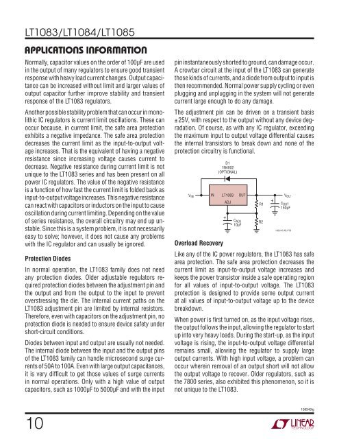
The adjustment pin can be driven on a transient basis<br />
±25V, with respect to the output without any device degradation.<br />
Of course, as with any IC regulator, exceeding<br />
the maximum input to output voltage differential causes<br />
the internal transistors to break down and none of the<br />
protection circuitry is functional.<br />
VIN<br />
D1<br />
1N4002<br />
(OPTIONAL)<br />
IN <strong>LT1083</strong><br />
ADJ<br />
OUT<br />
+<br />
C ADJ<br />
10μF<br />
R1<br />
R2<br />
+<br />
V OUT<br />
C OUT<br />
150μF<br />
1083/4/5 ADJ F00<br />
Overload Recovery<br />
Like any of the IC power regulators, the <strong>LT1083</strong> has safe<br />
area protection. The safe area protection decreases the<br />
current limit as input-to-output voltage increases and<br />
keeps the power transistor inside a safe operating region<br />
for all values of input-to-output voltage. The <strong>LT1083</strong><br />
protection is designed to provide some output current<br />
at all values of input-to-output voltage up to the device<br />
breakdown.<br />
When power is fi rst turned on, as the input voltage rises,<br />
the output follows the input, allowing the regulator to start<br />
up into very heavy loads. During the start-up, as the input<br />
voltage is rising, the input-to-output voltage differential<br />
remains small, allowing the regulator to supply large<br />
output currents. With high input voltage, a problem can<br />
occur wherein removal of an output short will not allow<br />
the output voltage to recover. Older regulators, such as<br />
the 7800 series, also exhibited this phenomenon, so it is<br />
not unique to the <strong>LT1083</strong>.<br />
108345fg