AN124 - Linear Technology
AN124 - Linear Technology
AN124 - Linear Technology

Create successful ePaper yourself
Turn your PDF publications into a flip-book with our unique Google optimized e-Paper software.
Application Note 124<br />
APPENDIX C<br />
Power, Grounding and Shielding Considerations<br />
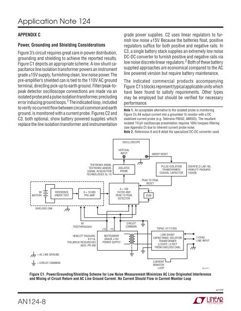
Figure 3’s circuit requires great care in power distribution,<br />
grounding and shielding to achieve the reported results.<br />
Figure C1 depicts an appropriate scheme. A low shunt capacitance<br />
line isolation transformer powers an instrument<br />
grade ±15V supply, furnishing clean, low noise power. The<br />
pre-amplifi er’s shielded can is tied to the 110V AC ground<br />
terminal, directing pick-up to earth ground. Filter/peak-topeak<br />
detector oscilloscope connections are made via an<br />
isolated probe and a pulse isolation transformer, precluding<br />
error inducing ground loops. 1 The indicated loop, included<br />
to verify no current fl ow between circuit common and earth<br />
ground, is monitored with a current probe. Figures C2 and<br />
C3, both optional, show battery powered supplies which<br />
replace the line isolation transformer and instrumentation<br />
9V<br />
BATTERY<br />
SHIELDED CAN<br />
<strong>AN124</strong>-8<br />
= AC LINE GROUND<br />
= CIRCUIT COMMON<br />
REFERENCE<br />
UNDER TEST<br />
A = 10,000<br />
PRE-AMP<br />
RF<br />
FEEDTHROUGHS<br />
HEWLETT PACKARD,<br />
6111A,<br />
PHILBRICK RESEARCHES<br />
6033, PR-300<br />
TEKTRONIX A6909,<br />
TEKTRONIX A6902B,<br />
SIGNAL ACQUISITION<br />
TECHNOLOGIES SL-10<br />
+15<br />
–15<br />
INSTRUMENT<br />
GRADE ±15V<br />
POWER SUPPLY<br />
grade power supplies. C2 uses linear regulators to furnish<br />
low noise ±15V. Because the batteries fl oat, positive<br />
regulators suffi ce for both positive and negative rails. In<br />
C3, a single battery stack supplies an extremely low noise<br />
DC-DC converter to furnish positive and negative rails via<br />
low noise discrete linear regulators. 2 Both of these battery<br />
supplied approaches are economical compared to the AC<br />
line powered version but require battery maintenance.<br />
The indicated commercial products accompanying<br />
Figure C1’s blocks represent typical applicable units which<br />
have been found to satisfy requirements. Other types<br />
may be employed but should be verifi ed for necessary<br />
performance.<br />
Note 1. An acceptable alternative to the isolated probe is monitoring<br />
Figure 3’s A4 output current into a grounded 1k resistor with a DC<br />
stabilized current probe (e.g. Tektronix P6042, AM503). The resultant<br />
isolated 1V/μV oscilloscope presentation requires 10Hz lowpass fi ltering<br />
(see Appendix D) due to inherent current probe noise.<br />
Note 2. References 6 and 8 detail the specialized DC-DC converter used.<br />
OSCILLOSCOPE<br />
VERTICAL<br />
INPUT<br />
ISOLATED<br />
PROBE<br />
A = 100<br />
FILTER AND<br />
PEAK TO PEAK<br />
DETECTOR<br />
CIRCUIT<br />
COMMON<br />
PEAK TO PEAK<br />
RESET<br />
+<br />
DVM<br />
–<br />
SWEEP RESET<br />
PULSE ISOLATION<br />
TRANSFORMER/<br />
COAXIAL CAPACITOR<br />
TOPAZ, 0111T35S<br />
LOW SHUNT<br />
CAPACITANCE ISOLATION<br />
TRANSFORMER<br />
(LOCATE ≥3 FEET<br />
FROM SHIELDED CAN)<br />
CURRENT<br />
MONITOR<br />
LOOP<br />
DEERFIELD LAB 185,<br />
HEWLETT PACKARD<br />
10240B<br />
110VAC<br />
LINE INPUT<br />
Figure C1. Power/Grounding/Shielding Scheme for Low Noise Measurement Minimizes AC Line Originated Interference<br />
and Mixing of Circuit Return and AC Line Ground Current. No Current Should Flow in Current Monitor Loop<br />
<strong>AN124</strong> FC1<br />
an124f