Linear Motors are Designed for High Linear Velocities and ... - Baldor
Linear Motors are Designed for High Linear Velocities and ... - Baldor
Linear Motors are Designed for High Linear Velocities and ... - Baldor

You also want an ePaper? Increase the reach of your titles
YUMPU automatically turns print PDFs into web optimized ePapers that Google loves.
<strong>Linear</strong> <strong>Motors</strong> <strong>are</strong> <strong>Designed</strong><br />
<strong>for</strong> <strong>High</strong> <strong>Linear</strong> <strong>Velocities</strong><br />
<strong>and</strong> <strong>High</strong> Acceleration<br />
<strong>Baldor</strong> has a wide variety of linear motors, positioning stages <strong>and</strong> controls <strong>for</strong> your application needs. They<br />
provide direct linear motion without mechanical linkages, there<strong>for</strong>e no backlash. St<strong>and</strong>ard <strong>and</strong> custom designs <strong>are</strong><br />
available. <strong>Baldor</strong> also has drives <strong>and</strong> motion controllers <strong>for</strong> powering <strong>and</strong> positioning of linear motors <strong>and</strong> stages.<br />
Advantages of <strong>Linear</strong> <strong>Motors</strong><br />
• <strong>High</strong> speeds – 200 in/sec [5 m/s] with encoder resolution > 1<br />
micron<br />
• <strong>High</strong> accelerations – up to 10 g’s [98 m/s]<br />
• Small, compact – fits into smaller spaces<br />
• Unlimited strokes from 0.01 in [0.000254 m]<br />
• Submicron positioning when coupled with appropriate<br />
feedback <strong>and</strong> bearings<br />
• No backlash from gears or slippage from belts – provides<br />
smooth operation<br />
• Reliability – non-contact operation reduces component wear<br />
<strong>and</strong> reduces maintenance<br />
<strong>Linear</strong> Motor Design Characteristics<br />
Types of <strong>Linear</strong> <strong>Motors</strong><br />
<strong>Baldor</strong> offers many types of linear motors to meet a variety of<br />
application requirements.<br />
• Cog-free brushless<br />
• Iron core brushless<br />
• DC brushed linear<br />
• AC induction<br />
• AC polynoid<br />
• DC non-commutated<br />
• Single axis stepper<br />
• Dual axis stepper<br />
Specification Description<br />
Ratings Models with peak <strong>for</strong>ces up to 1530 lbs [6800 N] with 10% duty cycle<br />
Acceleration St<strong>and</strong>ard <strong>and</strong> custom bearings available <strong>for</strong> up to 10 g’s (9.8 m/s)<br />
Accuracy Up to 0.0001 in/ft (2.5 µm/300 mm)<br />
Repeatability <strong>High</strong> repeatability models to 0.00004 inches (1 µm)<br />
Protection Internal thermal switch<br />
H-1<br />
Overview<br />
Motion<br />
DC <strong>Motors</strong> DC Controls AC <strong>Motors</strong> AC Controls<br />
Softw<strong>are</strong><br />
Controls<br />
<strong>Linear</strong><br />
<strong>Motors</strong><br />
<strong>Linear</strong><br />
Stages<br />
Engineering<br />
In<strong>for</strong>mation
Motion<br />
Overview Softw<strong>are</strong><br />
AC Controls AC <strong>Motors</strong> DC Controls DC <strong>Motors</strong><br />
Controls<br />
<strong>Linear</strong><br />
<strong>Motors</strong><br />
<strong>Linear</strong><br />
Stages<br />
Engineering<br />
In<strong>for</strong>mation<br />
<strong>Linear</strong> Motor Technology<br />
The same electromagnetic <strong>for</strong>ce that produces<br />
torque in a rotary motor also produces direct <strong>for</strong>ce in<br />
a linear motor. For example, a permanent magnet<br />
DC linear motor is similar to a permanent magnet DC<br />
rotary motor <strong>and</strong> an AC induction linear motor is<br />
similar to a squirrel cage induction motor.<br />
Take a rotary motor, split it radially along its axis of<br />
rotation <strong>and</strong> flatten it out. The result is a flat linear<br />
motor that produces direct linear <strong>for</strong>ce instead of<br />
torque. Why? Torque is <strong>for</strong>ce at a distance.<br />
Removing the distance (axis of rotation) leaves direct<br />
linear <strong>for</strong>ce. It follows that linear motors utilize the<br />
same controls as rotary motors. And similar to a<br />
rotary motor with rotary encoders, linear motor<br />
positioning is provided by a linear encoder.<br />
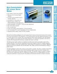
A variation of the linear motor is the tubular linear<br />
motor. This design rolls up the motor about an axis<br />
parallel to its length. This results in a “noncommutated”<br />
motor. Designs <strong>are</strong> available with either<br />
a moving coil or moving magnets.<br />
<strong>Linear</strong> Motor Per<strong>for</strong>mance<br />
<strong>Linear</strong> motor output is measured in Lbs. [N] of <strong>for</strong>ce or thrust:<br />
• <strong>Linear</strong> motors provide <strong>for</strong>ce to 2000 Lbs. [8900N],<br />
<strong>and</strong> speeds to 200 in/sec [5 m/s] depending upon<br />
encoder resolution.<br />
• <strong>High</strong>er speeds <strong>are</strong> possible with special controls<br />
H-2<br />
N S<br />
TORQUE<br />
N S<br />
N<br />
S<br />
FORCE<br />
Imaginary process of unrolling a rotary motor.<br />
Tubular non-commutated DC <strong>Linear</strong> Motor.<br />
<strong>Linear</strong> motors <strong>are</strong> capable of <strong>for</strong>ce based on the following primary/secondary <strong>are</strong>as:<br />
• Unlimited strokes from 0.01 in [0.000254m]<br />
• Submicron positioning when coupled with an<br />
appropriate feedback element <strong>and</strong> bearing system.<br />
• Acceleration up to 10g’s [98 m/s 2 ]<br />
<strong>Linear</strong> Motor F/A (Lb/in 2 ) [N/cm 2 ] at 100% Duty Cycle F/A (Lb/in 2 ) [N/cm 2 ] at 10% Duty Cycle<br />
Stepper 2.5 [1.75] 2.5 [1.75]<br />
DC Brush <strong>and</strong> Brushless 2.5 [1.75] 7.5 [5.25]<br />
AC <strong>Linear</strong> Induction 0.25 [0.18] 1.25 [0.88]
<strong>Linear</strong> Motor Product Characteristics Overview<br />
<strong>Baldor</strong> offers the largest selection of linear motors <strong>and</strong> stages available to assure that you get the best linear<br />
motor solution <strong>for</strong> your application.<br />
Cog-free Iron Core Brush<br />
<strong>Linear</strong> <strong>Motors</strong><br />
AC AC DC Non Single Dual<br />
Brushless Brushless Induction Polynoid Commutated Axis Axis<br />
Stepper Stepper<br />
Motor<br />
Series<br />
LMCF LMBL LMBR LMAC LMPY LMNM LMSS LMDS<br />
Continuous 1-173 10-500 4.2-55 15-100 1-20 0.5-50 2-50 2.5-30<br />
Force [4-250] [44-2220] [20-245] [67-445] [4-90] [2-220] [9-220] [10-130]<br />
Lbs [N]<br />
Peak Force 3-517 30-1530 13-171 70-500 5-54 1.58-150 2-50 2.5-30<br />
@ 10% [13-750] [133-6800] [60-760] [310-2225] [22-240] [7-667] [9-220] [10-130]<br />
Duty Lbs [N] (15% duty) (static) (static)<br />
AccelerationE 10 10 5 1 1 5 1 1<br />
g’s [m/s 2 ] [98] [98] [49] [9.8] [9.8] [49] [9.8] [9.8]<br />
Maximum 270 [6.8]<br />
Speed 200 200 75 @ 60 Hz 90 100 890 60<br />
in/sec [m/s] [5] [5] [1.8] 2000 [50.8] [2.3] [2.5] [2] [1.5]<br />
@ 400 Hz @400Hz<br />
Maximum Unlimited Unlimited 132 Unlimited 120 4 144 36 x 59<br />
Stroke in[m] [3.2] [3] [0.10] [3.7] [0.914x1.498]<br />
AccuracyQ 0.0001 0.0001 0.0001 0.0001 N/A 0.0001 0.001 0.001<br />
in/ft [µm/300mm] R [25] [2.5] [2.5] [2.5] [2.5] [2.5] [25]<br />
RepeatabilityQ 0.00004 0.00004 0.00004 0.00004 W N/A 0.00004 0.0004 0.0002<br />
in [µm] R [1] [1] [1] [1] [1] [10] [5.08]<br />
Positioning Closed Closed Closed Open or Open or Open or Open Open<br />
Type Loop Loop Loop Closed Loop Closed Loop Closed Loop Loop Loop<br />
Control 3-Phase 3-Phase PWM Single or 3 Single or <strong>Linear</strong> or Stepper Stepper<br />
Brushless Brushless DC Phase AC Line 3 Phase Brushless Motor Motor<br />
Control Control Control or Adj. Speed AC Line Control Driver Driver<br />
Load Customer Customer Customer Customer Rulon <strong>Linear</strong> Roller or Air<br />
Support Supplied Supplied Supplied Supplied Bearing Recirculating Air Bearing<br />
Bearing Bearing Bearing Bearing Jewel Bearing<br />
Sapphire or<br />
Bronze Bearing<br />
NOTES: All specifications <strong>are</strong> <strong>for</strong> reference only.<br />
Q Encoder dependent<br />
W Vector control required, <strong>and</strong> encoder dependent<br />
E Acceleration is dependant on amount of mass attached.<br />
R Accuracy <strong>and</strong> repeatability <strong>are</strong> referenced against a laser interferometer. Tighter tolerances <strong>are</strong> available.<br />
H-3<br />
Overview<br />
Motion<br />
DC <strong>Motors</strong> DC Controls AC <strong>Motors</strong> AC Controls<br />
Softw<strong>are</strong><br />
Controls<br />
<strong>Linear</strong><br />
<strong>Motors</strong><br />
<strong>Linear</strong><br />
Stages<br />
Engineering<br />
In<strong>for</strong>mation
Motion<br />
Overview Softw<strong>are</strong><br />
AC Controls AC <strong>Motors</strong> DC Controls DC <strong>Motors</strong><br />
Controls<br />
<strong>Linear</strong><br />
<strong>Motors</strong><br />
<strong>Linear</strong><br />
Stages<br />
Engineering<br />
In<strong>for</strong>mation<br />
Cog-free Brushless<br />
Servo Motor<br />
The Cog-free brushless linear motor is<br />
designed <strong>for</strong> unlimited stroke (travel) servo<br />
applications that require smooth operation<br />
without cogging. These motors <strong>are</strong> supplied in<br />
kit <strong>for</strong>m to be integrated into a customer’s<br />
machine. They <strong>are</strong> used in closed-loop servo<br />
systems <strong>and</strong> provide optimum per<strong>for</strong>mance.<br />
Design Specifications<br />
• Peak <strong>for</strong>ces to 517 Lbs [2300 N]<br />
• <strong>High</strong> acceleration to 10g’s [98m/s2 ]<br />
• <strong>High</strong> speeds to 200 in/sec [5m/s] with encoder resolution > 1<br />
micron<br />
• Speeds to 100 in/sec with encoder resolutions ≤ 1 micron<br />
• <strong>High</strong> accuracy ±0.0001 in/ft [2.5µm/300m] (encoder dependent)<br />
• <strong>High</strong> repeatability 0.00004 in [1µm] (encoder dependent)<br />
H-4<br />
Features<br />
• Unlimited stroke length<br />
• Independent multiple coil operation with overlapping trajectories<br />
• No metal-to-metal contact, virtually maintenance free<br />
• Modular magnet tracks <strong>for</strong> ready shipment<br />
• Use with: Trapezoidal or sinusoidal 3-phase brushless control<br />
(refer to <strong>Baldor</strong> AC controls Flex/Flex+ Series).<br />
The linear brushless AC Cog-free servo motor consists of a stationary magnet track <strong>and</strong> a moving coil assembly.<br />
The U-shaped, multi-pole magnet track is comprised of alternating polarity r<strong>are</strong>-earth magnets bonded to a hardchrome<br />
plated, cold-rolled steel plate. Modular track assemblies stack end to end to provide the length of stroke<br />
required. The coil assembly must be centered within the U-shaped magnet track <strong>and</strong> guided by customer<br />
supplied bearings. Individual coil assemblies can be mounted in series (as a single unit) to increase <strong>for</strong>ce. Multiple<br />
coil assemblies having independent operation <strong>and</strong> overlapping trajectories can also be mounted on a single<br />
magnet track.<br />
The moving primary is a three-phase ironless core coil. The winding is encapsulated in thermally conductive<br />
epoxy. The ironless core eliminates the magnetic-attractive <strong>for</strong>ce between the coil assembly <strong>and</strong> the magnet<br />
track. A twisted shielded four conductor high flex cable supplies power to the coil assembly. The st<strong>and</strong>ard coil<br />
assembly is provided with Hall sensors <strong>for</strong> sinewave commutation alignment, trapezoidal commutation, <strong>and</strong> crash<br />
recovery. Custom designs without Hall sensors <strong>are</strong> available. An aluminum mounting bracket is integrated with the<br />
coil assembly. For improved heat dissipation <strong>and</strong> increased <strong>for</strong>ce, a water cooling option is available on some<br />
models.
Cog-free Brushless Servo Motor Technical Data<br />
Catalog Number<br />
LMCF LMCF LMCF LMCF LMCF LMCF LMCF<br />
Parameter<br />
General:<br />
Units 02A-HC0 02B-HC0 04B-HC0 02C-HC0 04C-HC0 06C-HC0 08C-HC0<br />
Continuous Force QWE Lbs [N] 1.2 [5.3] 3.1 [13.8] 6.2 [27.8] 6.5 [29] 13 [58] 19.5 [87] 26 [115.6]<br />
Continuous Current Amps 1.7 2.1 2.1 1.9 1.9 1.9 1.9<br />
Peak Force @ 10% Duty Lbs [N] 3.6 [16] 9.4 [41.8] 18.7 [83.3] 19.5 [86.8] 39 [173] 58 [260] 78.2 [347]<br />
Peak Current @ 10% Duty Amps 5.1 6.3 6.3 5.7 5.7 5.7 5.7<br />
Continuous Power Watts 11.0 19.6 39.3 24.8 49.5 74.3 99.0<br />
Mechanical:<br />
No. of Poles<br />
Coil Assembly Length<br />
2 2 4 2 4 6 8<br />
w/Hall Effect Sensors in [mm] 3.45 [87.6] 3.45 [87.6] 5.85 [148.6] 3.45 [87.6] 5.85 [148.6] 8.25 [209.6] 10.65 [270.5]<br />
w/o Hall Effect Sensors in [mm] 2.9 [73.7] 2.9 [73.7] 5.3 [134.6] 2.9 [73.7] 5.3 [134.6] 7.7 [195.6] 10.1 [256.5]<br />
Coil Assembly Weight Lbs [kg] 0.17 [0.08] 0.25 [0.11] 0.49 [0.22] 0.39 [0.18] 0.7 [0.32] 1.25 [0.57] 1.64 [0.75]<br />
Magnet Track Weight Lbs/inch 0.2 0.31 0.31 0.45 0.45 0.45 0.45<br />
Electrical:<br />
[kg/m] [3.6] [5.5] [5.5] [8.05] [8.05] [8.05] [8.05]<br />
Force Constant Lbs/Amp 0.7 1.5 3.0 3.4 6.8 10.3 13.7<br />
Ph - Ph [N/Amp] [3.1] [6.7] [13.2] [15.2] [30.4] [45.6] [60.9]<br />
Back EMF Constant V/in/sec 0.08 0.17 0.34 0.39 0.77 1.16 1.55<br />
Ph - Ph [V/m/sec] [3.1] [6.7] [13.2] [15.2] [30.4] [45.6] [60.9]<br />
Ph-Ph Resistance @ 25°C Ohms 2.7 3.2 6.4 5.3 10.6 15.9 21.1<br />
Thermal Resistance W/deg C 0.11 0.20 0.39 0.33 0.66 0.99 1.32<br />
Inductance Ph - Ph mH 3.2 15.9 4.0 12.1 10.6 15.9 21.2<br />
Electrical Time Constant msec 0.2 1.0 1.0 1.3 1.0 1.0 1.0<br />
Km Motor Constant Lb/W 0.43 0.84 1.17 1.49 2.1 2.6 2.97<br />
[N/W] [1.9] [3.7] [5.2] [6.6] [9.4] [11.5] [13.3]<br />
NOTES: All specifications <strong>are</strong> <strong>for</strong> reference only.<br />
Technical data at 75°C rise over 25°C ambient.<br />
Q Addition of 10 in x 10 in x 1 in aluminum heat sink increases continuous <strong>for</strong>ce by 20%.<br />
W Addition of <strong>for</strong>ced air cooling increases continuous <strong>for</strong>ce 12%.<br />
E Liquid cooling option increases continuous <strong>for</strong>ces by 25% <strong>and</strong> power dissipation by 50%. Available on D, E <strong>and</strong> F series motors only.<br />
H-5<br />
Overview<br />
Motion<br />
DC <strong>Motors</strong> DC Controls AC <strong>Motors</strong> AC Controls<br />
Softw<strong>are</strong><br />
Controls<br />
<strong>Linear</strong><br />
<strong>Motors</strong><br />
<strong>Linear</strong><br />
Stages<br />
Engineering<br />
In<strong>for</strong>mation
Motion<br />
Overview Softw<strong>are</strong><br />
AC Controls AC <strong>Motors</strong> DC Controls DC <strong>Motors</strong><br />
Controls<br />
<strong>Linear</strong><br />
<strong>Motors</strong><br />
<strong>Linear</strong><br />
Stages<br />
Engineering<br />
In<strong>for</strong>mation<br />
Cog-free Brushless Servo Motor Technical Data<br />
Catalog Number<br />
LMCF LMCF LMCF LMCF LMCF LMCF<br />
Parameter<br />
General:<br />
Units 02D-HC0 04D-HC0 06D-HC0 08D-HC0 10D-HC0 12D-HC0<br />
Continuous Force QWE Lbs [N] 8.3 [36.8] 16.5 [73.6] 24.8 [110] 33 [147] 41.3 [183.6] 49.6 [220.3]<br />
Continuous Current Amps 1.5 1.5 1.5 1.5 3.0 3.0<br />
Peak Force @ 10% Duty Lbs [N] 24.8 [110] 49.5 [220] 74.5 [331] 99 [441] 123 [550] 148 [660]<br />
Peak Current @ 10% Duty Amps 4.4 4.4 4.4 4.4 8.9 8.9<br />
Continuous Power Watts 25.9 51.8 77.6 103.5 129.4 155.3<br />
Mechanical:<br />
No. of Poles<br />
Coil Assembly Length<br />
2 4 6 8 10 12<br />
w/Hall Effect Sensor in [mm] 3.45 [87.6] 5.85 [148.6] 8.25 [209.6] 10.65 [270.5] 13.05 [331.5] 15.45 [392.4]<br />
w/o Hall Effect Sensor in [mm] 2.9 [74] 5.3 [135] 7.7 [196] 10.1 [257] 12.5 [318] 14.9 [378]<br />
Coil Assembly Weight Lbs [kg] 0.76 [0.35] 1.38 [0.6] 2 [0.9] 2.6 [1.2] 3.2 [1.5] 3.9 [1.8]<br />
Magnet Track Weight Lbs/inch 0.65 0.65 0.65 0.65 0.65 0.65<br />
Electrical:<br />
[kg/m] [11.63] [11.63] [11.63] [11.63] [11.63] [11.63]<br />
Force Constant Lbs/Amp 5.6 11.2 16.7 22.3 13.9 16.7<br />
Ph - Ph [N/Amp] [24.8] [49.6] [74.4] [99.3] [61.8] [74.2]<br />
Back EMF Constant V/in/sec 0.63 1.26 1.89 2.52 1.57 1.88<br />
Ph - Ph [V/m/sec] [24.8] [49.6] [74.4] [99.3] [61.8] [74.16]<br />
Ph-Ph Resistance @ 25°C Ohms 9.1 18.2 27.3 36.4 11.3 13.6<br />
Thermal Resistance W/deg C 0.35 0.69 1.04 1.38 1.73 2.07<br />
Inductance Ph - Ph mH 12.1 24.2 36.2 48.3 15.0 18.0<br />
Electrical Time Constant msec 1.3 1.3 1.3 1.3 1.3 1.3<br />
Km Motor Constant Lbs/W 1.85 2.61 3.2 3.7 4.1 4.51<br />
[N/W] [8.2] [11.6] [14.2] [16.4] [18.3] [20.1]<br />
NOTES: All specifications <strong>are</strong> <strong>for</strong> reference only.<br />
Technical data at 75°C rise over 25°C ambient.<br />
Q Addition of 10 in x 10 in x 1 in aluminum heat sink increases continuous <strong>for</strong>ce by 20%.<br />
W Addition of <strong>for</strong>ced air cooling increases continuous <strong>for</strong>ce 12%.<br />
E Liquid cooling option increases continuous <strong>for</strong>ces by 25% <strong>and</strong> power dissipation by 50%. Available on D, E <strong>and</strong> F series motors only.<br />
H-6
Cog-free Brushless <strong>Linear</strong> Motor Technical Data<br />
Catalog Number<br />
LMCF LMCF LMCF LMCF LMCF LMCF<br />
Parameter<br />
General:<br />
Units 04E-HC0 06E-HC0 08E-HC0 10E-HC0 12E-HC0 14E-HC0<br />
Continuous Force QWE Lbs [N] 28 [124] 42 [185] 56 [251] 70 [314] 85 [377] 99 [440]<br />
Continuous Current Amps 1.6 3.1 3.1 3.1 3.1 3.1<br />
Peak Force @ 10% Duty Lbs [N] 84 [372] 125 [556] 169 [753] 212 [942] 254 [1132] 297 [1321]<br />
Peak Current @ 10% Duty Amps 4.7 9.3 9.2 9.2 9.2 9.2<br />
Continuous Power Watts 71.3 106.9 142.1 178.1 214.1 250.1<br />
Mechanical:<br />
No. of Poles<br />
Coil Assembly Length<br />
4 6 8 10 12 14<br />
w/Hall Effect Sensor in [mm] 5.85 [148.6] 8.25 [209.6] 10.65 [270.5] 13.05 [331.5] 15.45 [392.4] 17.9 [453]<br />
w/o Hall Effect Sensor in [mm] 5.3 [135] 7.7 [196] 10.1 [257] 12.5 [318] 14.9 [378] 17.3 [439]<br />
Coil Assembly Weight Lbs [kg] 1.7 [0.77] 2.47 [1.12] 3.24 [1.47] 4.01 [1.82] 4.78 [2.17] 5.55 [2.52]<br />
Magnet Track Weight Lbs/inch 0.96 0.96 0.96 0.96 0.96 0.96<br />
Electrical:<br />
[kg/m] [17.2] [17.2] [17.2] [17.2] [17.2] [17.2]<br />
Force Constant Lbs/Amp 18 13.4 18.4 23.0 27.7 32.3<br />
Ph - Ph [N/Amp] [79.9] [59.7] [82] [102.5] [123] [143.5]<br />
Back EMF Constant V/in/sec 2.03 1.52 2.08 2.6 3.12 3.64<br />
Ph - Ph [V/m/sec] [79.9] [59.7] [82] [102.5] [123] [143.5]<br />
Ph-Ph Resistance @ 25°C Ohms 23 8.6 11.7 14.7 17.6 20.5<br />
Thermal Resistance W/deg C 0.95 1.43 1.90 2.38 2.86 3.34<br />
Inductance Ph - Ph mH 34.9 13.0 18.4 23.0 27.6 32.2<br />
Electrical Time Constant msec 1.5 1.5 1.6 1.6 1.6 1.6<br />
Km Motor Constant Lbs/W 3.7 4.6 5.4 6.0 6.6 7.1<br />
[N/W] [16.7] [20.4] [23.9] [26.7] [29.3] [31.7]<br />
NOTES: All specifications <strong>are</strong> <strong>for</strong> reference only.<br />
Technical data at 75°C rise over 25°C ambient.<br />
Q Addition of 10 in x 10 in x 1 in aluminum heat sink increases continuous <strong>for</strong>ce by 20%.<br />
W Addition of <strong>for</strong>ced air cooling increases continuous <strong>for</strong>ce 12%.<br />
E Liquid cooling option increases continuous <strong>for</strong>ces by 25% <strong>and</strong> power dissipation by 50%. Available on D, E <strong>and</strong> F series motors only.<br />
H-7<br />
Overview<br />
Motion<br />
DC <strong>Motors</strong> DC Controls AC <strong>Motors</strong> AC Controls<br />
Softw<strong>are</strong><br />
Controls<br />
<strong>Linear</strong><br />
<strong>Motors</strong><br />
<strong>Linear</strong><br />
Stages<br />
Engineering<br />
In<strong>for</strong>mation
Motion<br />
Overview Softw<strong>are</strong><br />
AC Controls AC <strong>Motors</strong> DC Controls DC <strong>Motors</strong><br />
Controls<br />
<strong>Linear</strong><br />
<strong>Motors</strong><br />
<strong>Linear</strong><br />
Stages<br />
Engineering<br />
In<strong>for</strong>mation<br />
Cog-free Brushless Servo Motor Technical Data<br />
Catalog Number<br />
LMCF LMCF LMCF LMCF<br />
Parameter<br />
General:<br />
Units 04F-HC0 08F-HC0 12F-HC0 16F-HC0<br />
Continuous Force QWE Lbs [N] 43 [191] 87 [387] 130 [578] 173 [771]<br />
Continuous Current Amps 2.6 2.6 3.9 5.2<br />
Peak Force @ 10% Duty Lbs [N] 130 [578] 256 [1152] 338 [1726] 517 [2300]<br />
Peak Current @ 10% Duty Amps 7.8 7.8 11.6 15.6<br />
Continuous Power Watts 91 182 273 364<br />
Mechanical:<br />
No. of Poles<br />
Coil Assembly Length*<br />
4 8 12 16<br />
w/Hall Effect Sensor in [mm] 6.15 [156.2] 10.95 [278.1] 15.75 [400] 20.55 [522]<br />
w/o Hall Effect Sensor in [mm] 5.6 [142.2] 10.4 [264.2] 15.2 [386.1] 20 [508]<br />
Coil Assembly Weight Lbs [kg] 3.64 [1.65] 6.76 [3.07] 9.88 [4.49] 13 [5.91]<br />
Magnet Track Weight Lbs/inch 1.9 1.9 1.9 1.9<br />
Electrical:<br />
[kg/m] [0.034] [0.034] [0.034] [0.034]<br />
Force Constant Lbs/Amp 16.72 33.44 33.34 33.24<br />
Ph - Ph [N/Amp] [74.4] [148.8] [148.4] [148.0]<br />
Back EMF Constant V/in/sec 1.89 3.78 3.77 3.76<br />
Ph - Ph [V/m/sec] [74.4] [148.4] [148.4] [148.0]<br />
Ph-Ph Resistance @ 25°C Ohms 10.5 21.0 14.0 10.4<br />
Hot Resistance Ohms 13.6 27.1 18.0 13.5<br />
Thermal Resistance W/deg C 1.2 2.4 3.6 4.9<br />
Inductance Ph - Ph mH 13.6 27.2 18.0 13.4<br />
Electrical Time Constant msec 1.3 1.3 1.3 1.3<br />
Km Motor Constant Lbs/W 5.15 7.3 8.93 10.29<br />
H-8<br />
[N/W] [22.9] [32.5] [39.7] [45.8]<br />
NOTES: All specifications <strong>are</strong> <strong>for</strong> reference only.<br />
Technical data at 75°C rise over 25°C ambient.<br />
Q Addition of 10 in x1 0 in x 1 in aluminum heat sink increases continuous <strong>for</strong>ce by 20%.<br />
W Addition of <strong>for</strong>ced air cooling increases continuous <strong>for</strong>ce 12%.<br />
E Liquid cooling option increases continuous <strong>for</strong>ces by 25% <strong>and</strong> power dissipation by 50%. Available on D, E <strong>and</strong> F series motors only.
Cog Free Brushless Servo Identification Matrix<br />
L M C F<br />
LINEAR<br />
MOTOR<br />
COG-FREE<br />
NO. OF POLES<br />
02, 04...18<br />
SIZE CODE Inch [mm]<br />
A = 1.6 [40.7]<br />
B = 2.11 [53.6]<br />
C = 2.25 [57.2]<br />
D = 3.4 [86.4]<br />
E = 4.5 [114.3]<br />
F = 6.0 [152.4]<br />
COOLING TYPE<br />
C=Convection<br />
A=Air<br />
W= Water<br />
HALLS<br />
H = Halls Effect Sensors<br />
N = No Halls<br />
Cog Free Magnet Track Identification Matrix<br />
L T C F<br />
LINEAR<br />
TRACK<br />
COG-FREE<br />
SIZE CODE Inch [mm]<br />
A = 1.6 [40.7]<br />
B = 2.11 [53.6]<br />
C = 2.25 [57.2]<br />
D = 3.4 [86.4]<br />
E = 4.5 [114.3]<br />
F = 6.0 [152.4]<br />
CODE FOR LENGTH<br />
OF MODULAR TRACK Inches [mm]<br />
04 = 4.8 [121.9]<br />
07 = 7.2 [182.9]<br />
09 = 9.6 [243.8]<br />
12 = 12 [304.8]<br />
24 = 24 [609.6]<br />
WINDING<br />
Blank = St<strong>and</strong>ard<br />
P = Parallel<br />
TERMINATION<br />
0 = Flying Leads (10 ft. Std.)<br />
H-9<br />
Overview<br />
Motion<br />
DC <strong>Motors</strong> DC Controls AC <strong>Motors</strong> AC Controls<br />
Softw<strong>are</strong><br />
Controls<br />
<strong>Linear</strong><br />
<strong>Motors</strong><br />
<strong>Linear</strong><br />
Stages<br />
Engineering<br />
In<strong>for</strong>mation
Motion<br />
Overview Softw<strong>are</strong><br />
AC Controls AC <strong>Motors</strong> DC Controls DC <strong>Motors</strong><br />
Controls<br />
<strong>Linear</strong><br />
<strong>Motors</strong><br />
<strong>Linear</strong><br />
Stages<br />
Engineering<br />
In<strong>for</strong>mation<br />
Size A Cog-free Brushless Motor Dimensions (Inches [mm])<br />
LMCF Size A Brushless 3 φ Coil Assembly (inches [mm])<br />
Catalog Number A B C<br />
LMCF02A-HC0 2.90 [73.7] 1.1 [27.94] .50 [12.7]<br />
H-10<br />
.460<br />
[11.68]<br />
1.600<br />
[40.64]<br />
.250 [6.35]<br />
.30 [7.5]<br />
GAP<br />
.820<br />
[20.83]<br />
1.085<br />
[27.56]<br />
.410<br />
[10.41] .60 [15.1]<br />
.150 [3.81]<br />
.410<br />
[10.41]<br />
1.20<br />
[30.4]<br />
1.200<br />
[30,48]<br />
TYPICAL<br />
D<br />
2.400 [60.96]<br />
TYPICAL<br />
1.200 [30.48]<br />
TYPICAL<br />
M4-.7 THRU<br />
OPTIONAL HALL LEADS<br />
MOTOR LEADS<br />
.550 [14] MUST BE IN TRACK<br />
(FOR HALL ONLY)<br />
LENGTH = 4.80 + N*2.4 (N = 0,1,2...)<br />
or Multiple of 1.2" <strong>for</strong> non-st<strong>and</strong>ard tracks<br />
(OPTIONAL<br />
HALL MODULE)<br />
.010 [.25]<br />
Ø .148 [3.7] THRU<br />
C'BORE .313 [7.9]<br />
X .115 [2.9] (BOTH SIDES)<br />
.550 [14] MUST BE IN TRACK<br />
(FOR HALL ONLY)<br />
M4 - .7 THRU<br />
OPTIONAL HALL LEADS<br />
MOTOR LEADS<br />
B<br />
TAP #4-40<br />
x .300 [7.5] DEEP<br />
(5 PLCS)<br />
A<br />
B C<br />
.075<br />
[1.91]<br />
"E" MOUNTING HOLES<br />
PER SECTION<br />
.670<br />
[17.02]<br />
LMCF Size A Magnet Track Assembly (inches [mm]) *<br />
Catalog Number D E<br />
LTCF-A04 4.8 [121.9] 2<br />
LTCF-A07 7.2 [182.9] 3<br />
LTCF-A09 9.6 [243.8] 4<br />
LTCF-A12 12.0 [304.8] 5<br />
LTCF-A24 24.0 [609.6] 10<br />
Size B Cog-free Brushless Motor Dimensions (Inches [mm])<br />
2.110<br />
[53.59]<br />
.460<br />
[11.68]<br />
.250 [6.35]<br />
.30 [.75]<br />
GAP<br />
.820<br />
[20.83]<br />
1.585<br />
[40.26]<br />
.150<br />
[3.81]<br />
1.20<br />
[30.4]<br />
.60<br />
[15.1]<br />
2.400 [60.96]<br />
TYPICAL<br />
.010 [0.25]<br />
LMCF Size B Brushless 3φ Coil Assembly (inches [mm])<br />
Catalog Number A B C<br />
LMCF02B-HC0 2.90 [73.7] 1.100 [27.94] .50 [12.7]<br />
LMCF04B-HC0 5.30 [134.6] 2.300 [58.42] .50 [12.7]<br />
D<br />
LENGTH = 4.80 + N*2.4 (N = 0,1,2...)<br />
or Multiple of 1.2" <strong>for</strong> non-st<strong>and</strong>ard tracks<br />
(OPTIONAL<br />
HALL MODULE)<br />
Ø .148 [3.7] THRU<br />
C'BORE .313 [7.9]<br />
x .115 [2.9] (BOTH SIDES)<br />
B B C<br />
TAP #4-40<br />
x .300 [7.6] DEEP<br />
(5 PLCS)<br />
NOTES: All specifications <strong>are</strong> <strong>for</strong> reference only.<br />
* Magnet tracks <strong>are</strong> modular <strong>and</strong> may be placed end to end to create longer track lengths.<br />
Minimum track length must be equal to stroke plus length of coil assembly. See “Sizing Track Length” in Application section.<br />
Maximum length (stroke plus coil) is 48 inches [1.22 meters] <strong>for</strong> single track piece.<br />
A<br />
.075<br />
[1.91]<br />
"E" MOUNTING HOLES<br />
PER SECTION<br />
.670<br />
[17.02]<br />
LTCF Size B Magnet Track Assembly (inches [mm]) *<br />
Catalog Number D E<br />
LTCF-B04 4.80 [121.9] 2<br />
LTCF-B07 7.20 [182.9] 3<br />
LTCF-B09 9.60 [243.8] 4<br />
LTCF-B12 12.00 [304.8] 5<br />
LTCF-B24 24.00 [609.6] 10
Size C Cog-free Brushless Motor Dimensions (Inches [mm])<br />
2.250<br />
[57.15]<br />
.025 [0.64]<br />
.345 [8.76]<br />
.250<br />
[6.35]<br />
.60 [15.1]<br />
1.250<br />
[31.75]<br />
.625 [15.88]<br />
1.200 [30.48]<br />
1.850<br />
[46.99]<br />
.015 [0.38]<br />
GAP<br />
.140<br />
[3.56]<br />
LMCF Size C Brushless 3φ Coil Assembly (inches [mm])<br />
Catalog Number A B C<br />
1.200 [30.48]<br />
TYPICAL<br />
TAP M5-.8 THRU<br />
1.20<br />
[30.4]<br />
LMCF02C-HC0 2.9 [73.66] 1.1 [27.94] 0.50 [12.7]<br />
LMCF04C-HC0 5.3 [134.62] 2.3 [58.42] 0.50 [12.7]<br />
LMCF06C-HC0 7.7 [195.58] 3.5 [88.90] 0.50 [12.7]<br />
LMCF08C-HC0 10.1 [256.54] 4.7 [119.38] 0.50 [12.7]<br />
OPTIONAL HALL LEADS<br />
D<br />
2.400 [60.96]<br />
TYPICAL<br />
MOTOR LEADS<br />
.010 [0.25]<br />
.550 (14) MUST BE IN TRACK<br />
(FOR HALL ONLY)<br />
TAP #6-32 X .25 (6.3) DP<br />
(5 PLCS)<br />
LENGTH = 4.8 .8 + N* N*2.4 2.4 (N= 0,1,2,... 0,1,2,...) ) OR<br />
MULTIPLE OF 1.2 IN. FOR NON-STANDARD TRACKS<br />
OPTIONAL<br />
HALL MODULE<br />
0.172 [4.3] THRU<br />
C'BORE .313 [7.9]<br />
X 0.225 [5.7] (BOTH SIDES)<br />
B B C<br />
.150<br />
[3.81]<br />
"E" MOUNTING HOLES<br />
PER SECTION<br />
.900<br />
[22.86]<br />
LTCF Size C Magnet Track Assembly (inches [mm]) *<br />
Catalog Number D E<br />
LTCF-C04 4.8 [121.92] 2<br />
LTCF-C07 7.2 [182.88] 3<br />
LTCF-C09 9.6 [243.84] 4<br />
LTCF-C12 12.0 [304.80] 5<br />
LTCF-C24 24.0 [609.60] 10<br />
Size D Cog-free Brushless Motor Dimensions (Inches [mm])<br />
3.400<br />
[86.36]<br />
.650 [16.51]<br />
.438 [11.13]<br />
.013 [0.34]<br />
GAP<br />
1.350 [34.29]<br />
2.650<br />
[67.31]<br />
1.350<br />
[34.29]<br />
.675 [17.15]<br />
.250 [6.35]<br />
.60<br />
[15.1]<br />
1.20<br />
[30.4]<br />
1.200 [30.48]<br />
TYPICAL<br />
D<br />
2.400<br />
[60.96]<br />
TYPICAL<br />
LMCF Size D Brushless 3φ Coil Assembly (inches [mm])<br />
Catalog No. A B C<br />
LMCF02D-HC0 2.9 [73.66] 1.1 [27.94] 0.50 [12.7]<br />
LMCF04D-HC0 5.3 [134.62] 2.3 [58.42] 0.50 [12.7]<br />
LMCF06D-HC0 7.7 [195.58] 3.5 [88.9] 0.50 [12.7]<br />
LMCF08D-HC0 10.1 [256.54] 4.7 [119.38] 0.50 [12.7]<br />
LMCF10D-HC0 12.5 [317.5] 5.9 [149.86] 0.50 [12.7]<br />
TAP M6-1 THRU<br />
OPTIONAL HALL LEADS<br />
MOTOR LEADS<br />
LENGTH = 4.80 + N*2.4 (N = 0,1,2...) OR<br />
MULTIPLE OF 1.2" FOR NON-STANDARD TRACKS<br />
OPTIONAL<br />
HALL MODULE<br />
.010 [0.25]<br />
0.213 THRU<br />
C'BORE .394<br />
x .225 (BOTH SIDES)<br />
.550 [14] MUST BE IN TRACK<br />
(FOR HALL ONLY)<br />
B<br />
A<br />
A<br />
B<br />
C<br />
.150 [3.81]<br />
TAP #10-32 X .35<br />
(5 PLCS)<br />
"E" MOUNTING HOLES<br />
PER SECTION<br />
1.050<br />
[26.67]<br />
LTCF Size D Magnet Track Assembly (inches [mm]) *<br />
Catalog No. D E<br />
LTCF-D04 4.8 [121.92] 2<br />
LTCF-D07 7.2 [182.88] 3<br />
LTCF-D09 9.6 [243.84] 4<br />
LTCF-D12 12.0 [304.80] 5<br />
LTCF-D24 24.0 [609.60] 10<br />
LMCF12D-HC0 14.9 [378.46] 5.9 [149.86] 1.70 [43.2]<br />
NOTES: All specifications <strong>are</strong> <strong>for</strong> reference only.<br />
* Magnet tracks <strong>are</strong> modular <strong>and</strong> may be placed end to end to create longer track lengths.<br />
Minimum track length must be equal to stroke plus length of coil assembly. See “Sizing Track Length” in Application section.<br />
Maximum length (stroke plus coil) is 48 inches [1.22 meters] <strong>for</strong> single track piece.<br />
H-11<br />
Overview<br />
Motion<br />
DC <strong>Motors</strong> DC Controls AC <strong>Motors</strong> AC Controls<br />
Softw<strong>are</strong><br />
Controls<br />
<strong>Linear</strong><br />
<strong>Motors</strong><br />
<strong>Linear</strong><br />
Stages<br />
Engineering<br />
In<strong>for</strong>mation
Motion<br />
Overview Softw<strong>are</strong><br />
AC Controls AC <strong>Motors</strong> DC Controls DC <strong>Motors</strong><br />
Controls<br />
<strong>Linear</strong><br />
<strong>Motors</strong><br />
<strong>Linear</strong><br />
Stages<br />
Engineering<br />
In<strong>for</strong>mation<br />
Size E Cog-free Brushless Motor Dimensions (Inches [mm])<br />
H-12<br />
4.500<br />
[114.30]<br />
.025 [0.64]<br />
.695 [17.65]<br />
.700 [17.78]<br />
.025<br />
GAP<br />
1.550<br />
[39.37]<br />
3.750<br />
[95.25]<br />
1.600<br />
[40.64]<br />
.800<br />
[20.32] .60 [15.1]<br />
.350 [8.89]<br />
1.200 [30.48]<br />
TYPICAL<br />
1.20<br />
[30.4]<br />
2.400 [60.96]<br />
TYPICAL<br />
TAP M6-1 THRU<br />
LMCF Size E Brushless 3φ Coil Assembly (inches [mm])<br />
Catalog No. A B C<br />
LMCF04E-HC0 5.3 [134.62] 2.3 [58.42] 0.50 [12.7]<br />
LMCF06E-HC0 7.7 [195.58] 3.5 [88.90] 0.50 [12.7]<br />
LMCF08E-HC0 10.1 [256.54] 4.7 [119.38] 0.50 [12.7]<br />
LMCF10E-HC0 12.5 [317.50] 5.9 [149.86] 0.50 [12.7]<br />
LMCF12E-HC0 14.9 [378.46] 5.9 [149.86] 2.9 [73.66]<br />
LMCF14E-HC0 17.3 [439.42] 5.9 [149.86] 5.3 [134.62]<br />
D<br />
.550 [14] MUST BE IN TRACK<br />
(FOR HALL ONLY) B B C<br />
OPTIONAL HALL LEADS<br />
MOTOR LEADS<br />
LENGTH = 4.80 + N*2.4 (N = 0,1,2,...) OR<br />
MULTIPLE OF 1.2" FOR NON-STANDARD TRACKS<br />
.01 [0.25]<br />
DIA. .281 [7.1] THRU<br />
C'BORE .438 [11.11]<br />
x .35 [8.9] DP (BOTH SIDES)<br />
(OPTIONAL<br />
HALL MODULE)<br />
LMCF Size F Brushless 3φ Coil Assembly (inches [mm])<br />
TAP 1/4-20<br />
x .400 DEEP<br />
(5 PLCS)<br />
A<br />
"E" MOUNTING HOLES<br />
PER SECTION<br />
.150 [3.81]<br />
1.250<br />
[31.75]<br />
LTCF Size E Magnet Track Assembly (inches [mm]) *<br />
Catalog No. D E<br />
LTCF-E04 4.8 [121.92] 2<br />
LTCF-E07 7.2 [182.88] 3<br />
LTCF-E09 9.6 [243.84] 4<br />
LTCF-E12 12.0 [304.80] 5<br />
LTCF-E24 24.0 [609.60] 10<br />
Size F Cog-free Brushless Motor Dimensions (Inches [mm])<br />
Catalog No. A B C D E F G<br />
LMCF04F-HC0 3.150 [80.00] — — — — — 5.60 [142.2]<br />
LMCF08F-HC0 2.362 [60.00] 5.512 [140.00] 7.874 [200.00] — — — 10.40 [264.2]<br />
LMCF12F-HC0 3.150 [80.00] 6.299 [160.00] 9.449 [240.00] 12.598 [320.00] — — 15.20 [386.1]<br />
LMCF16F-HC0 3.150 [80.00] 6.299 [160.00] 8.661 [220.00] 11.024 [280.00] 14.173 [360] 17.323 [440] 20.00 [508.0]<br />
NOTES: All specifications <strong>are</strong> <strong>for</strong> reference only.<br />
* Magnet tracks <strong>are</strong> modular <strong>and</strong> may be placed end to end to create longer track lengths.<br />
Size F CogFree brushless motor magnet tracks must be ordered as custom.<br />
Minimum track length must be equal to stroke plus length of coil assembly. See “Sizing Track Length” in Application section.<br />
Maximum length (stroke plus coil) is 48 inches [1.22 meters] <strong>for</strong> single track piece.<br />
LTCF Size E<br />
Magnet Track Assembly<br />
(inches [mm]) *<br />
Catalog No. V R<br />
LTCF-E04 4.8 [121.92] 2<br />
LTCF-E07 7.2 [182.88] 3<br />
LTCF-E09 9.6 [243.84] 4<br />
LTCF-E12 12.0 [304.80] 5<br />
LTCF-E24 24.0 [609.60] 10
Iron Core Brushless<br />
<strong>Linear</strong> Servo Motor<br />
The BL Series brushless linear motors <strong>are</strong><br />
designed <strong>for</strong> unlimited stroke (travel) linear<br />
positioning applications. This motor is<br />
supplied in kit <strong>for</strong>m, designed to be<br />
integrated into a customer’s machine. They<br />
<strong>are</strong> used in closed-loop servo systems <strong>and</strong><br />
provide high <strong>for</strong>ces.<br />
Design Specifications<br />
• <strong>High</strong> <strong>for</strong>ces to 1530 Lbs. [6800 N]<br />
• <strong>High</strong> acceleration to 10g’s [98 m/s2 ]<br />
• <strong>High</strong> speeds to 200 in/sec [5 m/s] with encoder resolution<br />
> 1 micron<br />
• Speeds to 100 in/sec. [2.5 m/sec] with encoder resolution<br />
≤ 1 micron<br />
• <strong>High</strong> accuracy ±0.0001 in/ft<br />
[2.5 µm/300mm] (encoder dependent)<br />
• <strong>High</strong> repeatability ±0.00004 in [1µm] (encoder dependent)<br />
Features<br />
• Unlimited stroke length<br />
• Magnetic-attractive <strong>for</strong>ce between coil assembly <strong>and</strong> magnet<br />
track used as preload <strong>for</strong> bearing system<br />
• Magnets skewed to reduce cogging<br />
• Coil features reduce cogging<br />
• Multiple coil independent operation with overlapping trajectories<br />
• Non-contact, virtually maintenance free<br />
• Lowest cost per pound of thrust brushless linear motor<br />
• Use with trapezoidal or sinusoidal 3-phase brushless control<br />
(refer to <strong>Baldor</strong>’s AC Controls – Flex/Flex+ Series)<br />
The iron core brushless servomotors consist of stationary magnet track <strong>and</strong> a moving coil assembly supported by<br />
customer-supplied bearings. The stationary magnet track is comprised of multi-pole alternating polarity r<strong>are</strong> earth<br />
permanent magnets bonded to a hard-chromed cold-rolled steel plate. An air gap of 0.025 in [0.635 mm] must<br />
be maintained <strong>for</strong> proper motor operation. Mounting holes <strong>are</strong> provided in the magnet track <strong>for</strong> secure installation.<br />
The moving coil consists of a steel laminated coil assembly encapsulated in thermally conductive epoxy. The<br />
st<strong>and</strong>ard coil assembly is provided with hall effect sensors <strong>for</strong> sinewave commutation alignment, crash recovery<br />
<strong>and</strong> when trapezoidal commutation is used. Custom designs without hall effect sensors <strong>are</strong> available. The moving<br />
coil assembly has mounting holes provided.<br />
H-13<br />
Overview<br />
Motion<br />
DC <strong>Motors</strong> DC Controls AC <strong>Motors</strong> AC Controls<br />
Softw<strong>are</strong><br />
Controls<br />
<strong>Linear</strong><br />
<strong>Motors</strong><br />
<strong>Linear</strong><br />
Stages<br />
Engineering<br />
In<strong>for</strong>mation
Motion<br />
Overview Softw<strong>are</strong><br />
AC Controls AC <strong>Motors</strong> DC Controls DC <strong>Motors</strong><br />
Controls<br />
<strong>Linear</strong><br />
<strong>Motors</strong><br />
<strong>Linear</strong><br />
Stages<br />
Engineering<br />
In<strong>for</strong>mation<br />
Iron Core Brushless Motor Technical Data<br />
LMBL<br />
Catalog Number<br />
LMBL LMBL LMBL LMBL LMBL<br />
Parameter<br />
General:<br />
Units 02A-HC0 04A-HC0 06A-HC0 06B-HC0 08A-HC0 08B-HC0<br />
Continuous Force Lbs [N] 10 [44.5] 15.0 [66.8] 20 [89] 30 [133.4] 30 [133.4] 45 [200]<br />
Continuous Current Amps 1.0 1.6 1.7 3.6 2.6 5.5<br />
Peak Force @ 10% Duty Lbs [N] 30 [133.5] 45 [200.3] 60 [267] 90 [400] 90 [400] 135 [600]<br />
Peak Current @ 10% Duty Amps 3 4.8 5.1 10.8 7.8 16.5<br />
Continuous Power Watts 27 54 57 86 110 165<br />
Attractive Force<br />
Mechanical:<br />
Lbs [N] 200 [900] 300 [1330] 400 [1780] 600 [2670] 500 [2220] 750 [3340]<br />
No. of Poles 2 4 6 6 8 8<br />
Coil Assembly LengthQ in [mm] 4.55 [116] 6.35 [161] 8.15 [207] 8.15 [207] 9.95 [253] 9.95 [253]<br />
Coil Assembly Weight Lbs [kg] 2.0 [0.91] 2.5 [1.14] 3.8 [1.7] 4.45 [2.02] 4.7 [2.2] 5.94 [2.7]<br />
Magnet Track Weight Lbs/inch 0.27 0.27 0.27 0.40 0.27 0.40<br />
Electrical:<br />
NOTES: All specifications <strong>are</strong> <strong>for</strong> reference only.<br />
Technical data at 100°C rise over 25°C ambient.<br />
Q Coil Assembly Length is same with or without Hall Effect Sensors.<br />
Water cooling option available <strong>for</strong> higher <strong>for</strong>ces.<br />
H-14<br />
[kg/m] [4.8] [4.8] [4.8] [7.2] [4.8] [7.2]<br />
Force Constant Lbs/Amp 10 9.4 11.7 8.3 11.5 8.2<br />
Ph - Ph [N/Amp] [44.5] [41.8] [52] 36.9 [51.2] [36.5]<br />
Back EMF Constant V/in/sec 1.13 1.06 1.32 0.94 1.30 0.92<br />
Ph - Ph [V/m/sec] [44.5] [41.8] [52] 36.9 [51.2] [36.5]<br />
Ph-Ph Resistance @ 25°C Ohms 19 15 14 4.7 11.6 3.9<br />
Ph-Ph Resistance @ 125°C 26.5 20.9 19.5 6.5 16.2 5.4<br />
Thermal Resistance W/deg C 0.27 0.54 0.57 0.86 1.10 1.65<br />
Inductance Ph - Ph mH 53 62 59 23.2 46.8 18.7<br />
Electrical Time Constant msec 2.79 4.13 4.21 4.94 4.03 4.79<br />
Km Motor Constant Lbs/W 1.94 2.05 2.64 3.24 2.86 3.50<br />
[N/W] 8.63 9.12 11.76 14.43 12.74 15.58
Iron Core Brushless Motor Technical Data<br />
Catalog Number<br />
LMBL LMBL LMBL LMBL LMBL LMBL LMBL LMBL<br />
Parameter<br />
General:<br />
Units 10A-HC0 10B-HC0 12A-HC0 12B-HC0 14A-HC0 14B -HC0 16A-HC0 16B-HC0<br />
Continuous Force Lbs [N] 40 [177.9] 60 [270] 50 [222] 75 [330] 60 [267] 90 [400] 70 [311.5] 105 [470]<br />
Continuous Current Amps 3.3 6.9 4.5 7.6 4.2 6.0 6.1 6.5<br />
Peak Force @ 10% Duty Lbs [N] 120 [533] 180 [800] 150 [667] 225[1000] 180 [800] 270 [1200] 210 [934] 315 [1400]<br />
Peak Current @ 10% Duty Amps 9.9 20.8 13.5 22.7 12.5 18.0 18.3 19.4<br />
Continuous Power Watts 139 209 122 183 140 210 186 279<br />
Attractive Force<br />
Mechanical:<br />
Lbs [N] 600 [2700] 900 [4000] 700 [3100] 1050 [4670] 800 [3560] 1200 [5340] 900 [4000] 1350 [6000]<br />
No. of Poles 10 10 12 12 14 14 16 16<br />
Coil Assembly LengthQ in [mm] 11.75 [299] 11.75 [299] 13.55 [345] 13.55 [345] 15.35 [390] 15.35 [390] 17.15 [436] 17.15 [436]<br />
Coil Assembly Weight Lbs [kg] 5.5 [2.5] 7.43 [3.37] 6.5 [2.9] 8.78 [3.98] 7.7 [3.5] 10.13 [4.6] 8.5 [3.86] 11.48 [5.21]<br />
Magnet Track Weight Lbs/inch 0.27 0.40 0.27 0.40 0.27 0.40 0.27 0.40<br />
Electrical:<br />
[kg/m] [4.8] [7.2] [4.8] [7.2] [4.8] [7.2] [4.8] [7.2]<br />
Force Constant Lbs/Amp 12.1 8.10 11.1 9.9 14.4 15.0 11.5 16.3<br />
Ph - Ph [N/Amp] [53.8] [38.3] [49.4] [44.0] [64.1] [66.7] [51.2] [72.5]<br />
Back EMF Constant V/in/sec 1.37 0.98 1.25 1.12 1.63 1.7 1.30 1.84<br />
Ph - Ph [V/m/sec] [53.8] [38.3] [49.4] [44.0] [64.1] [66.7] [51.2] [72.5]<br />
Ph-Ph Resistance @ 25°C Ohms 10.2 3.1 4.3 2.3 5.8 4.2 3.6 4.8<br />
Ph-Ph Resistance @ 125°C 14.3 4.3 6.0 3.2 8.1 5.9 5.0 6.7<br />
Thermal Resistance W/deg C 1.39 2.09 1.22 1.83 1.4 2.10 1.86 2.79<br />
Inductance Ph - Ph mH 20.0 15.8 17.9 11.6 20.8 20.2 14.7 23.1<br />
Electrical Time Constant msec 1.96 5.10 4.16 5.04 3.59 4.81 4.08 4.81<br />
Km Motor Constant Lbs/W 3.2 4.16 4.53 5.54 5.07 6.21 5.13 6.29<br />
[N/W] [14.25] [18.48] [20.16] [24.66] [22.56] [27.62] [22.84] [27.96]<br />
NOTES: All specifications <strong>are</strong> <strong>for</strong> reference only.<br />
Technical data at 100°C rise over 25°C ambient.<br />
Q Coil Assembly Length is same with or without Hall Effect Sensors.<br />
Water cooling options available <strong>for</strong> higher <strong>for</strong>ces.<br />
H-15<br />
Overview<br />
Motion<br />
DC <strong>Motors</strong> DC Controls AC <strong>Motors</strong> AC Controls<br />
Softw<strong>are</strong><br />
Controls<br />
<strong>Linear</strong><br />
<strong>Motors</strong><br />
<strong>Linear</strong><br />
Stages<br />
Engineering<br />
In<strong>for</strong>mation
Motion<br />
Overview Softw<strong>are</strong><br />
AC Controls AC <strong>Motors</strong> DC Controls DC <strong>Motors</strong><br />
Controls<br />
<strong>Linear</strong><br />
<strong>Motors</strong><br />
<strong>Linear</strong><br />
Stages<br />
Engineering<br />
In<strong>for</strong>mation<br />
Iron Core Brushless Motor Technical Data<br />
Catalog Number<br />
LMBL LMBL<br />
Parameter<br />
General:<br />
Units 18A-HC0 18B-HC0<br />
Continuous Force Lbs [N] 80 [356] 120 [530]<br />
Continuous Current Amps 4.8 5.1<br />
Peak Force @ 10% Duty Lbs [N] 240 [1070] 360 [1602]<br />
Peak Current @ 10% Duty Amps 14.5 15.4<br />
Continuous Power Watts 210 315<br />
Attractive Force<br />
Mechanical:<br />
Lbs [N] 1000 [4450] 1500 [6670]<br />
No. of Poles 18 18<br />
Coil Assembly LengthQ in [mm] 18.95 [482] 18.95 [482]<br />
Coil Assembly Weight Lbs [kg] 9.3 [4.2] 12.55 [5.7]<br />
Magnet Track Weight Lbs/inch 0.27 0.40<br />
Electrical:<br />
H-16<br />
[kg/m] [4.83] [7.2]<br />
Force Constant Lbs/Amp 16.6 23.4<br />
Ph - Ph [N/Amp] [73.8] [104.1]<br />
Back EMF Constant V/in/sec 1.88 2.64<br />
Ph - Ph [V/m/sec] [73.8] [104.1]<br />
Ph-Ph Resistance @ 25°C Ohms 6.5 8.6<br />
Ph-Ph Resistance @ 125°C 9.1 12.0<br />
Thermal Resistance W/deg C 2.10 3.15<br />
Inductance Ph - Ph mH 26.8 42.1<br />
Electrical Time Constant msec 4.12 4.9<br />
Km Motor Constant Lbs/W 5.52 6.76<br />
[N/W] [24.53] [30.07]<br />
NOTES: All specifications <strong>are</strong> <strong>for</strong> reference only.<br />
Technical data at 100°C rise over 25°C ambient.<br />
Q Coil Assembly Length is same with or without Hall Effect Sensors.<br />
Water cooling option available <strong>for</strong> higher <strong>for</strong>ces.
Iron Core Brushless Motor Technical Data<br />
Catalog Number<br />
LMBL LMBL<br />
Parameter<br />
General:<br />
Units 08E-HC0 17E-HC0<br />
Continuous Force Lbs [N] 250 [1110] 500 [2224]<br />
Continuous Current Amps 6.6 14.7<br />
Peak Force @ 10% Duty Lbs [N] 790 [3520] 1530 [7030]<br />
Peak Current @ 10% Duty Amps 19.8 44.1<br />
Continuous Power Watts 1394 3000<br />
Attractive Force<br />
Mechanical:<br />
Lbs [N] 3645 [16213] 7290 [32426]<br />
No. of Poles 8 17<br />
Coil Assembly LengthQ in [mm] 16.6 [421.64] 32.8 [833.12]<br />
Coil Assembly Weight Lbs [kg] 45 [20] 80 [36]<br />
Magnet Track Weight Lbs/inch 1.1 1.1<br />
Electrical:<br />
[kg/m] [19.7] [19.7]<br />
Force Constant Lbs/Amp 38 34<br />
Ph - Ph [N/Amp] [169] [151]<br />
Back EMF Constant V/in/sec 4.3 3.8<br />
Ph - Ph [V/m/sec] [169] [150]<br />
Ph-Ph Resistance @ 75°C Ohms 23 10<br />
Ph-Ph Resistance @ 125° C 32.0 13.9<br />
Thermal Resistance W/deg C 13.9 30.0<br />
Inductance Ph - Ph mH 94 42<br />
Electrical Time Constant msec 4.1 4.2<br />
Km Motor Constant Lbs/W 7.9 10.76<br />
[N/W] [35.16] [47.88]<br />
NOTES: All specifications <strong>are</strong> <strong>for</strong> reference only.<br />
Technical data at 100°c rise over 25°C ambient.<br />
Q Coil Assembly length is same with or without Hall Effect Sensors.<br />
H-17<br />
Overview<br />
Motion<br />
DC <strong>Motors</strong> DC Controls AC <strong>Motors</strong> AC Controls<br />
Softw<strong>are</strong><br />
Controls<br />
<strong>Linear</strong><br />
<strong>Motors</strong><br />
<strong>Linear</strong><br />
Stages<br />
Engineering<br />
In<strong>for</strong>mation
Motion<br />
Overview Softw<strong>are</strong><br />
AC Controls AC <strong>Motors</strong> DC Controls DC <strong>Motors</strong><br />
Controls<br />
<strong>Linear</strong><br />
<strong>Motors</strong><br />
<strong>Linear</strong><br />
Stages<br />
Engineering<br />
In<strong>for</strong>mation<br />
Brushless Catalog Identification Matrix<br />
L M B L -<br />
LINEAR<br />
MOTOR<br />
BRUSHLESS<br />
NO. OF POLES<br />
02, 04, 06...18<br />
SIZE CODE FOR WIDTH OF COIL ASSEMBLY<br />
inch [mm]<br />
A= 3 [76.2]<br />
B= 4 [101.6]<br />
E= 8.25 [209.55]<br />
L T B L<br />
LINEAR<br />
TRACK<br />
BRUSHLESS<br />
H-18<br />
SIZE CODE FOR WIDTH<br />
OF COIL ASSEMBLY<br />
Inch [mm]<br />
A= 3 [76.2]<br />
B= 4 [101.16]<br />
E= 8.25 [209.55]<br />
COOLING TYPE<br />
C = Convection<br />
A = Air<br />
W = Water<br />
HALLS<br />
H = Halls Effect Sensors<br />
N = No Halls<br />
TERMINATION<br />
0 = Flying Leads (10 ft. Std)<br />
Brushless Magnet Track Catalog Identification Matrix<br />
-<br />
CODE FOR LENGTH OF MODULAR TRACK<br />
Inch [mm]<br />
}<br />
05 = 5.4 [137.16]<br />
07 = 7.2 [182.63] For Sizes A & B<br />
18 = 18 [457.2]<br />
}<br />
07 = 7.2 [182.63]<br />
10 = 10.8 [274.32] For Size E<br />
25 = 25.2 [640.08]
“A” Width Iron Core Brushless Motor Dimensions<br />
(Inches [mm])<br />
0.46 [11.68]<br />
MOTOR LEADS<br />
(2"MIN BEND RAD.)<br />
3.0<br />
[76.2]n<br />
0.025<br />
[0.6]<br />
GAP<br />
1.735 [44.1]<br />
0.41[10.41]<br />
HALL EFFECT<br />
MODULE<br />
LMBL SizeA 3φ Coil Assembly (inches [mm])<br />
Catalog Number A B C<br />
5.4+N*1.8 (N=0,1,2...)<br />
TAP #10-32x0.35 (B PLCS)<br />
1.8 [45.72]<br />
(A PLCS)<br />
1.3 [33]<br />
0.23 [5.842]<br />
0.1<br />
[2.54]<br />
0.225 [5.7]<br />
0.25 [6.35]<br />
C 0.25 [6.35]<br />
LMBL02A-HC0 2 6 4.05 [102.87]<br />
LMBL04A-HC0 3 8 5.85 [148.59]<br />
LMBL06A-HC0 4 10 7.65 [194.31]<br />
LMBL08A-HC0 5 12 9.45 [240.03]<br />
LMBL10A-HC0 6 14 11.25 [285.75]<br />
LMBL12A-HC0 7 16 13.05 [331.47]<br />
LMBL14A-HC0 8 18 14.85 [377.19]<br />
LMBL16A-HC0 9 20 16.65 [422.91]<br />
LMBL18A-HC0 10 22 18.45 [468.63]<br />
N=To be determined<br />
NOTES: All specifications <strong>are</strong> <strong>for</strong> reference only.<br />
Q Modular magnet tracks may be placed end to end to create longer track lengths.<br />
D<br />
0.281 [7.1]<br />
(D pls. per piece)<br />
1.8<br />
[45.72]<br />
TYPICAL<br />
0.9<br />
[22.86]<br />
TAP 1/4-20x 0.25<br />
(E PLACES PER PIECE)<br />
0.225 [5.7]<br />
0.25 [6.35]<br />
2.5 [63.5]<br />
0.25 [6.35]<br />
LTBL Size A Magnet Track Assembly (inches [mm]) Q<br />
Catalog Number D E<br />
LTBL-A05 5.4 [137.16] 6<br />
LTBL-A07 7.2 [182.98] 8<br />
LTBL-A18 18.0 [457.20] 20<br />
H-19<br />
Overview<br />
Motion<br />
DC <strong>Motors</strong> DC Controls AC <strong>Motors</strong> AC Controls<br />
Softw<strong>are</strong><br />
Controls<br />
<strong>Linear</strong><br />
<strong>Motors</strong><br />
<strong>Linear</strong><br />
Stages<br />
Engineering<br />
In<strong>for</strong>mation
Motion<br />
Overview Softw<strong>are</strong><br />
AC Controls AC <strong>Motors</strong> DC Controls DC <strong>Motors</strong><br />
Controls<br />
<strong>Linear</strong><br />
<strong>Motors</strong><br />
<strong>Linear</strong><br />
Stages<br />
Engineering<br />
In<strong>for</strong>mation<br />
“B” Width Iron Core Brushless Motor Dimensions<br />
(Inches [mm])<br />
H-20<br />
MOTOR LEADS<br />
(2" [50.8]<br />
MIN BEND RAD.)<br />
0.025<br />
[0.6]<br />
GAP<br />
4<br />
[101.6]<br />
1.735<br />
[44.1]<br />
2.76<br />
[70.1]<br />
HALL EFFECT<br />
MODULE<br />
0.41 [10.41]<br />
LMBL Size B 3φ Coil Assembly (inches [mm])<br />
Catalog Number A B C<br />
5.40+Nx1.8 (N=0,1,2...)<br />
0.40 [10.16] TAP #10-32x0.35 [8.89]<br />
D<br />
(B PLCS)<br />
0.01 [0.2] 0.281[7.1] (D PLACES<br />
1.8 [45.72]<br />
PER PIECE)<br />
(A PLCS)<br />
1.15 [29.21]<br />
0.25 [6.35]<br />
C<br />
LMBL06B-HC0 4 10 7.65 [194.31]<br />
LMBL08B-HC0 5 12 9.45 [240.03]<br />
LMBL10B-HC0 6 14 11.25 [285.75]<br />
LMBL12B-HC0 7 16 13.05 [331.47]<br />
LMBL14B-HC0 8 18 14.85 [377.19]<br />
LMBL16B-HC0 9 20 16.65 [422.91]<br />
LMBL18B-HC0 10 22 18.45 [468.63]<br />
0.225 [5.7]<br />
TAP 1/4-20x0.25 [6.35]<br />
(E PLACES PER PIECE)<br />
0.25 [6.35]<br />
N=To be determined<br />
NOTES: All specifications <strong>are</strong> <strong>for</strong> reference only.<br />
Q Modular magnet tracks may be placed end to end to create longer track lengths.<br />
1.8<br />
[45.72]<br />
TYPICAL<br />
0.9<br />
[22.86]<br />
0.196 [5.0]<br />
0.25 [6.35]<br />
3.5 [88.9]<br />
0.25 [6.35]<br />
LTBL Size B Magnet Track Assembly (inches [mm]) *<br />
Catalog Number D E<br />
LTBL-B05 5.4 [137.16] 6<br />
LTBL-B07 7.2 [182.88] 8<br />
LTBL-B18 18.0 [457.20] 20<br />
“E” Width Iron Core Brushless Motor Dimensions<br />
(Inches [mm])<br />
.600<br />
[15.24]<br />
1.950<br />
[49.53]<br />
.365<br />
[9.27]<br />
D<br />
.010 [.25]<br />
GAP<br />
7.2 [182.6]+N*3.6 (N = 1,2,3,...)<br />
3.600 A<br />
[91.44]<br />
TYP.<br />
TAP M6 - 1 x .35 DP.<br />
(B PLACES)<br />
.100 [2.54]<br />
Ø .281 [7.14] THRU<br />
C/BORE Ø .438 [11.13] x .125 [3.18] DP<br />
(E PLACES PER PIECE)<br />
HALL CABLE<br />
1.500 [38.10]<br />
LMBL Size E Iron Core 3φ Coil Assembly (inches [mm])<br />
Catalog Number A B C<br />
2.700<br />
[68.58]<br />
LMBL08E-HC0 2.9 [73.66] 10 16.6 [421.64]<br />
LMBL17E-HC0 2.9 [73.66] 22 32.8 [833.2]<br />
C<br />
A<br />
OPTIONAL<br />
WATER<br />
COOLER<br />
3/8 I.D. TUBE<br />
BARBED<br />
FITTING<br />
1.500 [38.10]<br />
.100 [2.54]<br />
MOTOR CABLE<br />
.615<br />
[15.62]<br />
8.250<br />
[209.55]<br />
2.520<br />
[64.01]<br />
7.500<br />
[190.50]<br />
.035 [.89]<br />
GAP<br />
LMBL Size E Magnet Track Assembly (inches [mm])Q<br />
Catalog Number D E<br />
LTBL-E07 7.2 [182.6] 4<br />
LTBL-E10 10.8 [274.32] 6<br />
LTBL-E25 25.2 [604.8] 14
DC Brushed <strong>Linear</strong><br />
Servo <strong>Motors</strong><br />
The brushed linear servo motor is designed <strong>for</strong><br />
long stroke servo applications. It is ideal <strong>for</strong> direct<br />
linear motion without mechanical linkages in<br />
closed-loop position packages.<br />
Design Specifications<br />
• <strong>High</strong> <strong>for</strong>ces to 171 Lbs. [1070 N]<br />
• <strong>High</strong> acceleration to 5g’s [49 m/s2 ]<br />
• <strong>High</strong> speeds to 75 in/sec [3.8 m/s]<br />
• <strong>High</strong> accuracy ±0.0001 in/ft<br />
[8.3 µm/m] (encoder dependent)<br />
• <strong>High</strong> repeatability 0.00004 in<br />
[1 µm] (encoder dependent)<br />
• Stroke lengths to 11 ft. [3.2 m]<br />
Features<br />
• Multiple moving magnet assemblies<br />
with overlapping trajectories<br />
• Self-commutation enables the use of<br />
low-cost brush-type amplifiers.<br />
• Relatively low cost per pound of thrust<br />
comp<strong>are</strong>d to brushless linear motors<br />
• Use with PWM brush-type servo control<br />
(refer to <strong>Baldor</strong>’s DC Controls – LD Series)<br />
The moving permanent magnet brush commutated DC linear motor consists of a stationary primary <strong>and</strong> a<br />
moving secondary. The stationary primary is a steel laminated core, with multiple coils inserted into insulated<br />
slots. The ends of each coil <strong>are</strong> connected to a commutator bar that is mounted on an aluminum angle.<br />
The moving secondary features multiple permanent magnets <strong>and</strong> brushes <strong>for</strong> commutation. A cable supplies<br />
power to the moving secondary. Mounting holes <strong>are</strong> located on both the primary <strong>and</strong> secondary.<br />
The magnetic-attractive <strong>for</strong>ce between the primary <strong>and</strong> secondary can be used as a magnetic preload <strong>for</strong> the<br />
bearing system. The customer-supplied bearing system must maintain an air gap of 0.025 inch [0.064 cm]<br />
between the primary <strong>and</strong> secondary. The brush linear motor is available in different cross sections to meet<br />
different <strong>for</strong>ce requirements.<br />
H-21<br />
Overview<br />
Motion<br />
DC <strong>Motors</strong> DC Controls AC <strong>Motors</strong> AC Controls<br />
Softw<strong>are</strong><br />
Controls<br />
<strong>Linear</strong><br />
<strong>Motors</strong><br />
<strong>Linear</strong><br />
Stages<br />
Engineering<br />
In<strong>for</strong>mation
Motion<br />
Overview Softw<strong>are</strong><br />
AC Controls AC <strong>Motors</strong> DC Controls DC <strong>Motors</strong><br />
Controls<br />
<strong>Linear</strong><br />
<strong>Motors</strong><br />
<strong>Linear</strong><br />
Stages<br />
Engineering<br />
In<strong>for</strong>mation<br />
DC Brushed <strong>Linear</strong> Motor Technical Data<br />
LMBR<br />
Catalog Number<br />
LMBR LMBR LMBR LMBR LMBR<br />
Parameter<br />
General:<br />
Units 06-20 06-28 06-33 06-35 06-43 06-48<br />
Continuous Force Lbs [N] 4.2 [18.7] 11 [48.9] 15 [66.7] 17 [75.6] 24 [106] 29 [129]<br />
Continuous Current Amps 4.8 5 5 5 5.1 5.1<br />
Peak Force @ 10% Duty Lbs [N] 13 [57.8] 33 [146.8] 47 [209] 54 [240] 75 [333] 89 [395]<br />
Peak Amps @ 10% Duty Amps 15 16 16 16 16 16<br />
Continuous Power Watts 32 56 66 73 94 105<br />
Attractive Force<br />
Mechanical:<br />
Lbs [N] 45 [200] 110 [490] 160 [711] 180 [800] 250 [1112] 290 [1290]<br />
Motor Width in [mm] 2.0 [50.8] 2.8 [71.1] 3.3 [83.8] 3.5 [88.9] 4.3 [109.2] 4.8 [121.9]<br />
Moving Secondary Length in [mm] 4.38 [111.3] 4.38 [111.3] 4.38 [111.3] 4.38 [111.3] 4.38 [111.3] 4.38 [111.3]<br />
Moving Secondary Weight Lbs [kg] 1.05 [0.477] 1.33 [0.605] 1.90 [0.864] 2.02 [0.918] 2.38 [1.08] 2.63 [1.19]<br />
Stationary Primary Weight Lbs/Inch 0.25 0.43 0.53 0.59 0.75 0.86<br />
Electrical:<br />
[kg/m] [4.47] [7.68] [9.47] [10.55] [13.41] [15.37]<br />
Force Constant Lbs/Amp 0.9 2.2 3 3.5 4.8 5.6<br />
Ph - Ph [N/Amp] [4.0] [9.8] [13.4] [15.6] [21.3] [24.9]<br />
Back EMF Constant V/in/sec 0.1 0.2 0.3 0.4 0.5 0.6<br />
Ph - Ph [V/m/sec] [3.9] [7.9] [11.8] [15.7] [19.7] [23.6]<br />
Ph-Ph Resistance @ 25°C Ohms 1 1.6 1.9 2.1 2.6 2.9<br />
Ph-Ph Resistance @ 125°C 1.4 2.2 2.6 2.9 3.6 4.0<br />
Thermal Resistance W/deg C 0.32 0.56 0.66 0.73 0.94 1.05<br />
Inductance Ph - Ph mH 1.2 2.9 4.1 4.7 6.5 7.7<br />
Electrical Time Constant msec 1.2 1.9 2.2 2.3 2.6 2.7<br />
Km Motor Constant Lbs/W .742 1.470 1.846 1.990 2.475 2.830<br />
NOTE: All specifications <strong>are</strong> <strong>for</strong> reference only.<br />
H-22<br />
[N/W] [3.302] [6.538] [8.213] [8.850] [11.011] [12.588]
DC Brushed <strong>Linear</strong> Motor Technical Data<br />
LMBR<br />
Catalog Number<br />
LMBR LMBR LMBR LMBR LMBR<br />
Parameter<br />
Operating:<br />
Units 12-20 12-28 12-33 12-35 12-43 12-48<br />
Continuous Force Lbs [N] 8.1 [36] 21 [93] 29 [129] 34 [151] 47 [209] 55 [244]<br />
Continuous Current Amps 9.4 9.6 9.7 9.8 9.8 9.8<br />
Peak Force @ 10% Duty Lbs [N] 25 [111] 65 [289] 91 [404] 104 [462] 144 [640] 171 [760]<br />
Peak Current @ 10% Duty Amps 29 29 30 30 30 31<br />
Continuous Power Watts 62 103 118 134 174 187<br />
Attractive Force<br />
Mechanical:<br />
Lbs [N] 90 [400] 225 [1000] 315 [1400] 360 [1600] 495 [2200] 585 [2600]<br />
Motor Width in [mm] 2.0 [50.8] 2.8 [71.1] 3.3 [83.8] 3.5 [88.9] 4.3 [109.2] 4.8 [121.9]<br />
Moving Secondary Length in [mm] 8.44 [214.4] 8.44 [214.4] 8.44 [214.4] 8.44 [214.4] 8.44 [214.4] 8.44 [214.4]<br />
Moving Secondary Weight Lbs [kg] 2.10 [0.25] 2.66 [1.20] 3.8 [1.72] 4.04 [1.83] 4.76 [2.16] 5.26 [2.40]<br />
Stationary Primary Weight Lbs/Inch 0.25 0.43 0.53 0.59 0.75 0.86<br />
Electrical:<br />
[kg/m] [4.47] [7.68] [9.47] [10.54] [13.4] [15.37]<br />
Force Constant Lbs/Amp 0.9 2.2 3 3.5 4.8 5.6<br />
Ph - Ph [N/Amp] [4.0] [9.8] [13.4] [15.6] [21.3] [24.9]<br />
Back EMF Constant V/in/sec 0.1 0.2 0.3 0.4 0.5 0.6<br />
Ph - Ph [V/m/sec] [3.9] [7.9] [11.8] [15.7] [19.7] [23.6]<br />
Ph-Ph Resistance @ 25°C Ohms 0.5 0.8 0.9 1 1.3 1.4<br />
Ph-Ph Resistance @ 125°C 0.7 1.1 1.3 1.4 1.8 2.0<br />
Thermal Resistance W/deg C 0.62 1.03 1.18 1.34 1.74 1.87<br />
Inductance Ph - Ph mH 0.6 1.5 2.1 2.4 3.3 3.8<br />
Electrical Time Constant msec 1.2 1.9 2.2 2.3 2.6 2.7<br />
Km Motor Constant Lbs/wW 1.029 2.069 2.670 2.937 3.563 4.022<br />
NOTE: All specifications <strong>are</strong> <strong>for</strong> reference only.<br />
[N/wW] [4.576] [9.204] [11.875] [13.064] [15.848] [17.890]<br />
H-23<br />
Overview<br />
Motion<br />
DC <strong>Motors</strong> DC Controls AC <strong>Motors</strong> AC Controls<br />
Softw<strong>are</strong><br />
Controls<br />
<strong>Linear</strong><br />
<strong>Motors</strong><br />
<strong>Linear</strong><br />
Stages<br />
Engineering<br />
In<strong>for</strong>mation
Motion<br />
Overview Softw<strong>are</strong><br />
AC Controls AC <strong>Motors</strong> DC Controls DC <strong>Motors</strong><br />
Controls<br />
<strong>Linear</strong><br />
<strong>Motors</strong><br />
<strong>Linear</strong><br />
Stages<br />
Engineering<br />
In<strong>for</strong>mation<br />
DC Brushed <strong>Linear</strong> Motor <strong>and</strong> Control Selection Guide<br />
H-24<br />
Input Vac<br />
115 VAC 1 Ph<br />
Cont. Force Peak Force Cont Peak Motor Max Speed Single-Axis Dual-Axis<br />
Lbs. N Lbs. N Amps Amps Catalog In/s m/s Control Control<br />
Number Catalog No. Catalog No.<br />
4.2 18.7 13 57.9 4.8 15 LMBR06-20 75 1.9 LD2-01S LD2-02S<br />
11 49.0 33 146.9 5 15 LMBR06-28 75 1.9 LD2-01S LD2-02S<br />
15 66.8 47 209.2 5 16 LMBR06-33 75 1.9 LD2-01S LD2-02S<br />
17 75.7 54 240.3 5 16 LMBR06-35 75 1.9 LD2-01S LD2-02S<br />
24 106.8 75 333.8 5.1 16 LMBR06-43 75 1.9 LD2-01S LD2-02S<br />
29 129.1 89 396.1 5.1 16 LMBR06-48 75 1.9 LD2-01S LD2-02S<br />
8.1 36.0 25 111.3 9.4 29 LMBR12-20 75 1.9 LD2-01S LD2-02S<br />
21 93.5 65 289.3 9.6 29 LMBR12-28 75 1.9 LD2-01S LD2-02S<br />
29 129.1 91 405.0 9.7 30 LMBR12-33 75 1.9 LD2-01S LD2-02S<br />
34 151.3 104 462.8 9.8 30 LMBR12-35 75 1.9 LD2-01S LD2-02S<br />
47 209.2 144 640.8 9.8 30 LMBR12-43 75 1.9 LD2-01S LD2-02S<br />
55 244.8 171 761.0 9.8 31 LMBR12-48 75 1.9 LD2-01S LD2-02S<br />
DC Brushed <strong>Linear</strong> Servo Motor Identification Matrix<br />
L M B R<br />
TYPE<br />
<strong>Linear</strong> Motor<br />
Brush<br />
NO. OF POLES<br />
06, 12<br />
CODE FOR WIDTH OF COIL ASSEMBLY<br />
Inch [mm]<br />
20= 2.00 [50.8]<br />
25 = 2.50 [63.5]<br />
28 = 2.75 [69.85]<br />
30 = 3.00 [76.2]<br />
33 = 3.25 [82.55]<br />
35 = 3.50 [88.9]<br />
40 = 4.00 [101.6]<br />
43 = 4.25 [108]<br />
45 = 4.50 [114.3]<br />
50 = 5.00 [127]<br />
- -<br />
STROKE<br />
(Rounded Down<br />
to ne<strong>are</strong>st Inch)<br />
Max Length = 11 Feet<br />
(3.3 Meters)<br />
TERMINATION<br />
0 = Flying Leads<br />
(24” Std.)<br />
MOUNTING OPTION<br />
1 = Mounting Option 1<br />
2 = Mounting Option 2<br />
3 = Other
DC Brushed <strong>Linear</strong> Motor Dimensions (Inches [mm])<br />
OPTION 1<br />
A<br />
OPTION 2<br />
E<br />
.20<br />
[5.08]<br />
C<br />
N EQUAL SPACES OF 4.06 [103.1]<br />
L<br />
P EQUAL SPACES OF 4.500 [114.3]<br />
Width XY A in [mm] B in [mm] D in [mm]<br />
NOTE: All specifications <strong>are</strong> <strong>for</strong> reference only.<br />
NOTES: E = A + 1.00 (25.4)<br />
F = D + 1.60 (40.6)<br />
L = C + STROKE<br />
P = To Be Determined<br />
L<br />
10 – 32 X .25 [6.3] DP.<br />
6 – 32 X .30 [7.6] DP.<br />
B<br />
.20<br />
[5.08]<br />
D<br />
F<br />
1.75<br />
[44.5]<br />
1.75<br />
[44.5]<br />
.025<br />
[.63]<br />
GAP<br />
Ø.261 [6.63] THRU<br />
Primary Wgt. Secondary Wgt.<br />
Lbs/in [kg/m] Lbs [kg]<br />
20 2.00 [50.80] — 1.00 [25.4] 0.25 [4.47) 1.05 [0.47)<br />
28 2.75 [69.85] 1.03 [26.2] 1.75 [44.5] 0.43 [7.69] 1.33 [0.60]<br />
33 3.25 [82.55] 1.53 [38.9] 2.25 [57.2] 0.53 [9.48] 1.90 [0.86]<br />
35 3.50 [88.90] 1.53 [38.9] 2.50 [63.5] 0.59 [10.55] 2.02 [0.91]<br />
43 4.25 [108.0] 2.53 [64.3] 3.25 [82.6] 0.75 [13.42] 2.38 [1.08]<br />
48 4.75 [120.7] 3.03 [77.0] 3.75 [95.3] 0.86 [15.39] 2.63 [1.19]<br />
Model No. C in [mm] N<br />
LMBR06-XY 4.38 [111.3] 1<br />
LMBR12-XY 8.44 [214.4] 2<br />
H-25<br />
Overview<br />
Motion<br />
DC <strong>Motors</strong> DC Controls AC <strong>Motors</strong> AC Controls<br />
Softw<strong>are</strong><br />
Controls<br />
<strong>Linear</strong><br />
<strong>Motors</strong><br />
<strong>Linear</strong><br />
Stages<br />
Engineering<br />
In<strong>for</strong>mation
Motion<br />
Overview Softw<strong>are</strong><br />
AC Controls AC <strong>Motors</strong> DC Controls DC <strong>Motors</strong><br />
Controls<br />
<strong>Linear</strong><br />
<strong>Motors</strong><br />
<strong>Linear</strong><br />
Stages<br />
Engineering<br />
In<strong>for</strong>mation<br />
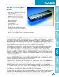
AC <strong>Linear</strong> Induction Motor<br />
The <strong>Linear</strong> Induction Motor (LIM) is designed <strong>for</strong> high<strong>for</strong>ce,<br />
long-stroke applications, such as material h<strong>and</strong>ling<br />
<strong>and</strong> people movers.<br />
Design Specifications<br />
• <strong>High</strong> <strong>for</strong>ces to 500 Lbs. [2,225 N] at 15% duty cycle<br />
• Acceleration to 1g [9.8 m/s2 ]<br />
• Speeds to 270 in/sec [6.85 m/s] at 60 Hz<br />
<strong>High</strong>er speeds at higher frequencies<br />
The single sided <strong>Linear</strong> Induction Motor consists of a primary coil assembly <strong>and</strong> a secondary called a reaction<br />
plate. The coil assembly is comprised of steel laminations <strong>and</strong> phase windings with a thermal sensor<br />
encapsulated in thermal epoxy. The customer supplied reaction plate is made of 1/8 inch thick aluminum or<br />
copper plate bonded to a 1/4 inch thick cold rolled steel. The aluminum faces the coil assembly. The width of a<br />
reaction plate must be equal to the width of the coil assembly. A customer supplied bearing system is used to<br />
maintain the 1/8 inch airgap between the coil <strong>and</strong> reaction plate over the length of the stroke.<br />
When AC voltage is applied to the coil windings, a traveling magnetic field is created. This induces current in the<br />
reaction plate which in turn creates its own magnetic field. The interaction of the two magnetic fields generates<br />
the <strong>for</strong>ce <strong>and</strong> direct linear motion.<br />
Either assembly or the reaction plate can be the moving member of the motor. Typically the reaction plate<br />
becomes part of the customer load moving over stationary coil assemblies placed end-to-end <strong>for</strong> the travel<br />
distance. In this configuration the length of the reaction plate must be equal to the center to center distance of<br />
two adjacent coil assemblies plus the length of one coil assembly. This will ensure the reaction plate covers<br />
adjacent coil assemblies at the point of transition from one coil to the next. Should the coil assembly be the<br />
moving element of the motor then the reaction plate length must be equal to the length of stroke plus the length<br />
of one coil assembly.<br />
Using two LIMs facing each other can provide increased <strong>for</strong>ce. This is known as a double sided linear induction<br />
motor. Here the reaction plate will consist only of a 1/4 inch thick aluminum plate without steel backing. The<br />
aluminum will require additional support over the length of the stroke.<br />
A variable frequency inverter will provide velocity control of a linear induction motor. A <strong>Linear</strong> Induction Motor (LIM)<br />
equipped with a linear encoder can do point to point programmable positioning when driven with a vector control<br />
<strong>and</strong> motion controller. These motors <strong>are</strong> supplied in kit <strong>for</strong>m with customer providing reaction plate (secondary) <strong>and</strong><br />
bearing system to be integrated into the application.<br />
H-26<br />
Features<br />
• Non-contact, virtually maintenance free<br />
• Heavy payloads<br />
• Unlimited stroke length<br />
• Use with:Single or three-phase AC line voltage, 50 or 60 Hz.<br />
Single-phase requires use of external capacitor<br />
• Use inverter <strong>for</strong> velocity control, or vector control <strong>and</strong> motion<br />
controller <strong>for</strong> positioning (refer to <strong>Baldor</strong>’s AC controls – 15H<br />
Inverter, 18H Vector, <strong>and</strong> Mint positioning controllers)
AC <strong>Linear</strong> Induction <strong>Motors</strong><br />
Force Amps<br />
Continuous Continuous Weight<br />
Catalog Number Lbs [N] 460VAC 3Ph Lbs [kg]<br />
LMAC1607C23D99 14 [62] 2.3 44 [20]<br />
LMAC1608C23D99 18 [80] 2.9 55 [25]<br />
LMAC1609C23D99 24 [106] 3.7 68 [31]<br />
LMAC1610C23D99 28 [124] 4.2 80 [36.2]<br />
LMAC1611C23D99 32 [142] 5.0 92 [41.6]<br />
LMAC1612C23D99 38 [169] 5.7 105 [47.5]<br />
LMAC1613C23D99 42 [186] 6.1 117 [52.9]<br />
LMAC1614C23D99 46 [204] 7.3 128 [57.9]<br />
LMAC1615C23D99 52 [231] 7.6 140 [63.3]<br />
LMAC1616C23D99 58 [258] 8.0 152 [68.8]<br />
LMAC3207C23D99 28 [124] 4.4 88 [39.8]<br />
LMAC3208C23D99 36 [160] 5.6 110 [49.8]<br />
LMAC3209C23D99 44 [195] 6.8 136 [61.5]<br />
LMAC3210C23D99 52 [231] 8.0 160 [72.4]<br />
LMAC3211C23D99 62 [275] 9.5 184 [83.3]<br />
LMAC3212C23D99 72 [320] 11.0 210 [95.0]<br />
LMAC3213C23D99 78 [347] 11.5 234 [105.9]<br />
LMAC3214C23D99 90 [400] 13.5 256 [115.8]<br />
LMAC3215C23D99 96 [427] 14.1 280 [126.7]<br />
LMAC3216C23D99 100 [445] 14.7 304 [137.6]<br />
Force @ 15% Amps @ 15%<br />
Duty Cycle Duty Cycle Weight<br />
Catalog Number Lbs [N] 460VAC 3Ph Lbs [kg]<br />
LMAC1607C23D15 70 [311] 11.5 44 [20]<br />
LMAC1608C23D15 90 [400] 14.5 55 [25]<br />
LMAC1609C23D15 120 [534] 18.5 68 [31]<br />
LMAC1610C23D15 140 [622] 21 80 [36.2]<br />
LMAC1611C23D15 160 [711] 25 92 [41.6]<br />
LMAC1612C23D15 190 [845] 28.5 105 [47.5]<br />
LMAC1613C23D15 210 [934] 30.5 117 [52.9]<br />
LMAC1614C23D15 230 [1023] 36.5 128 [57.9]<br />
LMAC1615C23D15 260 [1156] 38 140 [63.3]<br />
LMAC1616C23D15 290 [1289] 40 152 [68.8]<br />
LMAC3207C23D15 140 [622] 22 88 [39.8]<br />
LMAC3208C23D15 180 [800] 28 110 [49.8]<br />
LMAC3209C23D15 220 [978] 34 136 [61.5]<br />
LMAC3210C23D15 260 [1156] 40 160 [72.4]<br />
LMAC3211C23D15 310 [1378] 47.5 184 [83.3]<br />
LMAC3212C23D15 360 [1600] 55 210 [95.0]<br />
LMAC3213C23D15 390 [1434] 57.5 234 [105.9]<br />
LMAC3214C23D15 450 [2000] 67.5 256 [115.8]<br />
LMAC3215C23D15 480 [2135] 70.5 280 [126.7]<br />
LMAC3216C23D15 500 [2224] 73.5 304 [137.6]<br />
NOTE: All specifications <strong>are</strong> <strong>for</strong> reference only.<br />
H-27<br />
Overview<br />
Motion<br />
DC <strong>Motors</strong> DC Controls AC <strong>Motors</strong> AC Controls<br />
Softw<strong>are</strong><br />
Controls<br />
<strong>Linear</strong><br />
<strong>Motors</strong><br />
<strong>Linear</strong><br />
Stages<br />
Engineering<br />
In<strong>for</strong>mation
Motion<br />
Overview Softw<strong>are</strong><br />
AC Controls AC <strong>Motors</strong> DC Controls DC <strong>Motors</strong><br />
Controls<br />
<strong>Linear</strong><br />
<strong>Motors</strong><br />
<strong>Linear</strong><br />
Stages<br />
Engineering<br />
In<strong>for</strong>mation<br />
<strong>Linear</strong> Induction Motor Catalog Identification Matrix<br />
L M A C<br />
H-28<br />
LINEAR MOTOR<br />
AC INDUCTION<br />
COIL ASSEMBLY LENGTH<br />
In Inches: 16, 32<br />
AC <strong>Linear</strong> Induction Motor Dimensions (Inches [mm])<br />
D<br />
N EQUAL SPACES OF 6.00 (152.4mm)<br />
Ø 11/32 THRU MOUNTING HOLES<br />
D = TO BE DETERMINED<br />
N = TO BE DETERMINED<br />
Coil Assembly Dimensions (inches [mm])<br />
Catalog Number Q Catalog Number W A B C<br />
LMAC1607CXXXXX LMAC3207CXXXXX 6.5 [165.1] 7 [177.8] 5 [127]<br />
LMAC1608CXXXXX LMAC3208CXXXXX 7.5 [190.5] 8 [203.2] 6 [152.4]<br />
LMAC1609CXXXXX LMAC3209CXXXXX 8.5 [215.9] 9 [228.6] 7 [177.8]<br />
LMAC1610CXXXXX LMAC3210CXXXXX 9.5 [241.3] 10 [254] 8 [203.2]<br />
LMAC1611CXXXXX LMAC3211CXXXXX 10.5 [266.7] 11 [279.4] 9 [228.6]<br />
LMAC1612CXXXXX LMAC3212CXXXXX 11.5 [292] 12 [304.8] 10 [254]<br />
LMAC1613CXXXXX LMAC3213CXXXXX 12.5 [317.5] 13 [330.2] 11 [279.4]<br />
LMAC1614CXXXXX LMAC3214CXXXXX 13.5 [342.9] 14 [355.6] 12 [304.8]<br />
LMAC1615CXXXXX LMAC3215CXXXXX 14.5 [368.3] 15 [381] 13 [330.2]<br />
LMAC1616CXXXXX LMAC3216CXXXXX 15.5 [394] 16 [406.4] 14 [355.6]<br />
NOTE: All specifications <strong>are</strong> <strong>for</strong> reference only.<br />
Catalog No. ➀ D = 2.125 [54]<br />
E = 15.75 [400]<br />
N = 2<br />
COIL ASSY WIDTH<br />
07, 08...16<br />
COOLING<br />
C = Convection<br />
W = Water<br />
LEAD TYPE<br />
1 = Strain Relief<br />
2 = Flying Leads (36” Std)<br />
Catalog No. ➁ D = 1.0 [25.4]<br />
E = 31.5 [800]<br />
N = 5<br />
D<br />
C B A<br />
3.10 (78.8mm)<br />
GAP .125<br />
(3.2 mm)<br />
POWER & OVERLOAD LEADS<br />
ALUMINUM PLATE .125 (3.2mm) THK<br />
(CUSTOMER SUPPLIED)<br />
STEEL PLATE .250 (6.4mm) THK<br />
(CUSTOMER SUPPLIED)<br />
NO. PHASES<br />
1=Single-phase<br />
3 = Three-phase<br />
DUTY CYCLE<br />
00 < 1%<br />
50 = 50%<br />
99 = 100%<br />
VOLTAGE CODE OPTION<br />
A = 115 VAC<br />
B= 230 VAC<br />
C= 380 VAC<br />
D= 460/480 VAC<br />
E=550 VAC<br />
F=600 VAC
<strong>Linear</strong> Induction Motor Duty Cycle-Force-Current Curves<br />
Figure 1<br />
The <strong>for</strong>ce <strong>and</strong> current ratings shown in the<br />
per<strong>for</strong>mance table <strong>are</strong> based on 460VAC, threephase,<br />
60 Hz input at a 15% duty cycle <strong>and</strong> a 1/8<br />
inch airgap. To select a motor at other duty cycles,<br />
divide the required <strong>for</strong>ce by the duty cycle K factor<br />
rating on the curve corresponding to the required<br />
duty cycle. Select the closest equivalent or next<br />
higher rating from the per<strong>for</strong>mance table.<br />
Figure 2<br />
Provides the % <strong>for</strong>ce output versus the motor airgap<br />
in inches<br />
Figure 3<br />
Provides the % motor current versus the motor<br />
airgap in inches.<br />
Figure 4<br />
Provides the % motor current vs. % motor speed.<br />
Figure 5<br />
Plots % thrust (<strong>for</strong>ce) vs. % velocity.<br />
%<br />
FORCE<br />
%<br />
AMPS<br />
“k”<br />
1.6<br />
1.4<br />
1.2<br />
1.0<br />
.8<br />
.4<br />
120<br />
100<br />
0<br />
0 20 40 60 80 100 % DUTY CYCLE<br />
80<br />
60<br />
40<br />
20<br />
120<br />
100<br />
80<br />
0<br />
“K” FACTOR – DUTY CYCLE<br />
0 1/8 1/4 3/8 1/2<br />
AIRGAP INCHES<br />
0<br />
0 1/8 1/4 3/8 1/2<br />
AIRGAP INCHES<br />
H-29<br />
Overview<br />
Motion<br />
DC <strong>Motors</strong> DC Controls AC <strong>Motors</strong> AC Controls<br />
Softw<strong>are</strong><br />
Controls<br />
<strong>Linear</strong><br />
<strong>Motors</strong><br />
<strong>Linear</strong><br />
Stages<br />
Engineering<br />
In<strong>for</strong>mation
Motion<br />
Overview Softw<strong>are</strong><br />
AC Controls AC <strong>Motors</strong> DC Controls DC <strong>Motors</strong><br />
Controls<br />
<strong>Linear</strong><br />
<strong>Motors</strong><br />
<strong>Linear</strong><br />
Stages<br />
Engineering<br />
In<strong>for</strong>mation<br />
Polynoid <strong>Linear</strong> Motor<br />
The AC polynoid derives its name from the<br />
solenoid but the similarity stops there. Unlike a<br />
solenoid, the polynoid is a linear electric motor.<br />
Design Specifications<br />
• Acceleration to 1g [9.8 m/s2 ]<br />
• Speeds to 90 in/sec [2.3 m/s]<br />
• Optional built-in electronic brake (holding coil) <strong>for</strong> end holding<br />
• Integral rulon bearings<br />
• Low cost, powered by AC line voltage<br />
or adjustable speed with an inverter<br />
H-30<br />
Features<br />
• Provides long stroke with uni<strong>for</strong>m <strong>for</strong>ce<br />
• Stroke limited by end stops on moving rod<br />
• Limited duty cycle applications<br />
• Virtually maintenance free<br />
• Not <strong>for</strong> positioning applications<br />
• Use with:<br />
Single or 3-phase AC line voltage, 50 or 60 Hz<br />
Single-phase requires use of external capacitor<br />
The AC Polynoid provides a constant <strong>for</strong>ce <strong>for</strong> the entire length of its stroke. Its direction of travel is<br />
reversible by switching with equal <strong>for</strong>ce in both directions. Switching requires the swapping of any two of<br />
three motor leads in three-phase units while single-phase reversing is done by the swapping of one line lead<br />
to the opposite side of the capacitor lead. Electrical <strong>for</strong>ce reversal can be used <strong>for</strong> dynamic braking.<br />
A polynoid is comprised of two basic parts, a rod <strong>and</strong> a stator. The rod is copper clad steel, the end of<br />
which can feature a tapped mounting hole. An optional holding coil is available <strong>for</strong> end holding at one or<br />
both ends. The stator is a series of coils wound on bobbins. Coils <strong>are</strong> interconnected. The stator is housed<br />
in a smooth cold rolled steel assembly. It is also available finned <strong>for</strong> greater heat dissipation.<br />
The polynoid is an electrical induction motor. A sweeping magnetic field along the length of the stator coils<br />
induces linear motion of the rod through the stator or stator along the rod. The rod reacts to energization in<br />
less than 10 msecs accelerating to a limited speed. The time to reach this speed depends upon the net<br />
<strong>for</strong>ce available <strong>and</strong> the mass being moved. Normal operating speeds to 50 inches per second <strong>for</strong> singlephase<br />
units with three-phase units going to 90 inches per second.<br />
The rod can be of infinite length when provided with proper support. Output <strong>for</strong>ce can be as high as 100<br />
pounds (445 N) per stator with design capability <strong>for</strong> greater. The <strong>for</strong>ce can be controlled by varying the<br />
applied voltage (<strong>for</strong>ce varies by the squ<strong>are</strong> of the voltage) resulting in a degree of speed control.
Polynoid Selection<br />
FINNED SERIES provides maximum heat dissipation <strong>and</strong> higher<br />
duty cycle.<br />
SMOOTH SERIES is designed <strong>for</strong> applications where space is<br />
restricted. The smooth finned series provides <strong>for</strong>ce equal to the<br />
finned series, but at a lower duty cycle.<br />
STATOR SELECTION<br />
Required in<strong>for</strong>mation:<br />
1. Weight of all materials to be moved: Include rod at 1 lb/ft<br />
If rod is stationary, include stator weight listed in spec table.<br />
2. Friction: Measure with spring scale <strong>and</strong> include spring <strong>for</strong>ce<br />
is used.<br />
3. Mounting: horizontal or vertical<br />
4. Stroke length<br />
5. Cycle rate in strokes per minute<br />
A.To determine Stroke Time use appropriate graph at right:<br />
1. Follow the appropriate stroke length line to its intersection with<br />
the 0.35 <strong>for</strong>ce multiplier curve (2.00 <strong>for</strong>ce multiplier curve <strong>for</strong><br />
vertical application).<br />
2. Drop a line from this intersection to the base line <strong>and</strong> ready<br />
time. For three-phase power multiply the time by 0.75.<br />
3. This <strong>for</strong>ce multiplier will give the optimum cycling rate with<br />
minimum stator size.<br />
NOTE: If stroke time is too slow, use one of the curves to the left of the 0.35<br />
multiplier curve <strong>and</strong> repeat steps A1 <strong>and</strong> A2 using the new curve.<br />
If stroke time is too fast, try one of the curves to the right of the 0.35 <strong>for</strong>ce<br />
multiplier curve <strong>and</strong> follow steps A1 <strong>and</strong> A2 using new curve. If still too fast, use<br />
<strong>Baldor</strong> variable frequency inverter.<br />
B.To determine Duty Cycle: If powered in one direction, multiply<br />
stroke time times the cycles per minute times 1.6.<br />
If powered in both directions, multiply stroke time, times cycles<br />
per minute times 3.2.<br />
The required ON time per cycle should not exceed 10% of the<br />
continuous maximum on time shown in the specifications.<br />
C.To determine STATOR FORCE required:<br />
Horizontal mounting: Multiply all weights to be moved by<br />
0-.35 <strong>for</strong>ce multiplier. Add friction.<br />
Vertical Mounting: Multiply all weights to be moved by 2.00<br />
<strong>for</strong>ce multiplier. Add friction.<br />
NOTE: If the 0.35 or 2.00 <strong>for</strong>ce multipliers did not give adequate<br />
stroke time, use the <strong>for</strong>ce multiplier determined in A to determine<br />
stator <strong>for</strong>ce.<br />
ROD SELECTION<br />
Moving Rod:<br />
Rod length should be limited to approximately twice coil assembly<br />
length with no external rod support.<br />
Moving Coil Assembly:<br />
Rod length is unlimited. Rod diameter is 0.72 inches (1.83mm)<br />
with ends tapped 1/2 inch (12.5mm) – 13. Optional brass rod end<br />
adapters <strong>are</strong> drilled <strong>and</strong> tapped 5/16 inch (8mm) – 18.<br />
CAPACITOR SELECTION<br />
Single-phase capacitor selection guides <strong>are</strong> given on stator<br />
selection charts.<br />
H-31<br />
Overview<br />
Motion<br />
DC <strong>Motors</strong> DC Controls AC <strong>Motors</strong> AC Controls<br />
Softw<strong>are</strong><br />
Controls<br />
<strong>Linear</strong><br />
<strong>Motors</strong><br />
<strong>Linear</strong><br />
Stages<br />
Engineering<br />
In<strong>for</strong>mation
Motion<br />
Overview Softw<strong>are</strong><br />
AC Controls AC <strong>Motors</strong> DC Controls DC <strong>Motors</strong><br />
Controls<br />
<strong>Linear</strong><br />
<strong>Motors</strong><br />
<strong>Linear</strong><br />
Stages<br />
Engineering<br />
In<strong>for</strong>mation<br />
Single-Phase Smooth Series Polynoid Technical Data<br />
Max on Max Length<br />
Time <strong>for</strong> Cont. Bearing Current Capacitor<br />
Stall Duty Number Normal On To Coil Assembly Power Amps Code Number<br />
Force Cycle of Operation Time Bearing Catalog Number E<br />
Lbs % Coils secs secs In mm Watts 115/60 230/60 115/60 230/60<br />
3.7 3 2 0.8 8 2.1 53.34 LMPY0203-SX1X-X 600 5.3 2.6 C7 2-C5<br />
2.4 6 2 1.3 13 2.1 53.34 LMPY0206-SX1X-X 360 3.3 1.7 C2 C5<br />
H-32<br />
1 7 2 5.5 55 2.1 53.34 LMPY0207-SX1X-X 138 1.2 0.6 C8 C10<br />
7 3 4 1.2 12 3.1 78.74 LMPY0403-SX1X-X 865 7.8 3.9 C6 C8<br />
3.8 9 4 4.5 45 3.1 78.74 LMPY0409-SX1X-X 325 2.9 1.5 C9 C5<br />
1.9 21 4 8.5 85 2.9 73.66 LMPY0421-SX1X-X 175 1.6 0.8 C8 2-C4Q<br />
1 45 4 32.0 320 2.9 73.66 LMPY0445-SX1X-X 75 0.7 0.3 C1 C4<br />
10.8 2.2 6 1.8 18 4.1 104.14 LMPY0602-SX1X-X 920 NA 4.2 NA C8<br />
6 8 6 4.5 45 4.1 104.14 LMPY0608-SX1X-X 510 4.6 2.3 C7 C1,C10Q<br />
3 14 6 9.0 90 3.8 96.52 LMPY0614-SX1X-X 280 2.5 1.3 C9 C5<br />
1.5 30 6 31.5 315 3.8 96.52 LMPY0630-SX1X-X 127 1.1 0.6 C1,C10Q C4<br />
17.5 3 8 1.5 15 5.0 127 LMPY0803-SX1X-X 1625 14.8 6.7 C3 C2<br />
7.7 6 8 4.4 44 5.0 127 LMPY0806-SX1X-X 520 4.6 2.3 C7 C8<br />
4.2 9 8 6.0 60 4.6 116.84 LMPY0809-SX1X-X 356 3.4 1.7 C2 C5<br />
2.1 27 8 28.5 285 4.6 116.84 LMPY0827-SX1X-X 158 1.4 0.7 2-C1Q 2-C1W<br />
1.2 56 8 93.0 930 4.6 116.84 LMPY0856-SX1X-X 80 0.7 0.4 C1 C4<br />
27 3 12 1.8 18 7.0 177.8 LMPY103-SX1X-X 2250 20.0 10 C3,C 6Q C7<br />
12.5 6 12 4.5 45 7.0 177.8 LMPY1206-SX1X-X 1000 9.0 4.8 C6 C9<br />
6.9 9 12 8.0 80 6.3 160.02 LMPY1209-SX1X-X 565 5.1 2.5 C7 C8<br />
3.8 22 12 24.0 240 6.3 160.02 LMPY1222-SX1X-X 257 2.3 1.1 C9 C4,C10Q<br />
1.7 50 12 90.0 900 6.3 160.02 LMPY12050-SX1X-X 112 1.0 0.5 C1,C4Q C10<br />
1 100 12 — — 6.3 160.02 LMPY1299-SX1X-X 61 0.5 0.3 2-C4Q 2-C4Q<br />
NOTES: Q Capacitors wired in parallel.<br />
W Capacitors wired in series.<br />
NA – Not available at this voltage.<br />
All single-phase units used in intermittent duty applications will be supplied with overload protector.<br />
E Select codes <strong>for</strong> X. Refer to Catalog Identification Matrix.
Single-Phase Finned Series Polynoid Technical Data<br />
Max on Max Length<br />
Time <strong>for</strong> Cont. Bearing Current Capacitor<br />
Stall Duty Number Normal On To Coil Assembly Power Amps Code Number<br />
Force Cycle of Operation Time Bearing Catalog NumberE<br />
Lbs % Coils secs secs In mm Watts 115/60 230/60 115/60 230/60<br />
3.7 5 2 0.8 8 2.1 53.34 LMPY0205-FX1X-X 600 5.3 2.6 C7 2-C5<br />
2.4 7 2 1.3 13 2.1 53.34 LMPY0207-FX1X-X 360 3.3 1.7 C2 C5<br />
1 30 2 6.0 60 2.1 53.34 LMPY0230-FX1X-X 138 1.2 0.6 C8 C10<br />
7 5 4 1.2 12 3.1 78.74 LMPY0405-FX1X-X 865 7.8 3.9 C6 C8<br />
3.8 17 4 5.2 52 3.1 78.74 LMPY0417-FX1X-X 325 2.9 1.5 C9 C5<br />
1.9 30 4 9.5 95 2.9 73.66 LMPY0430-FX1X-X 175 1.6 0.8 C8 2-C4Q<br />
1 67 4 45.0 450 2.9 73.66 LMPY0467-FX1X-X 75 0.7 0.3 C1 C4<br />
10.8 5 6 2.0 20 4.1 104.14 LMPY0605-FX1X-X 920 NA 4.2 NA C8<br />
6 11 6 4.5 45 4.1 104.14 LMPY0611-FX1X-X 510 4.6 2.3 C7 C1,C10Q<br />
3 14 6 9.5 95 4.1 104.14 LMPY0614-FX1X-X 280 2.5 1.3 C9 C5<br />
1.5 45 6 36.0 360 3.8 96.52 LMPY0645-FX1X-X 127 1.1 0.6 C1,C10Q C4<br />
17.5 5 8 1.5 15 5.0 127 LMPY0805-FX1X-X 1625 14.8 6.7 C3 C2<br />
7.7 11 8 5.8 58 5.0 127 LMPY0811-FX1X-X 520 4.6 2.3 C7 C8<br />
4.2 20 8 9.0 90 4.6 116.84 LMPY0820-FX1X-X 356 3.4 1.7 C2 C5<br />
2.1 50 8 38.3 383 4.6 116.84 LMPY0850-FX1X-X 155 1.4 0.7 2-C1Q 2-C1W<br />
1.2 100 8 — — 4.6 116.84 LMPY0899-FX1X-X 75 0.7 0.4 C1 C4<br />
27 4 12 1.8 18 7.0 177.8 LMPY1204-FX1X-X 2250 20.0 10 C3,C 6Q C7<br />
12.5 15 12 6.0 60 7.0 177.8 LMPY1215-FX1X-X 1000 9.0 4.8 C6 C9<br />
6.9 20 12 8.0 80 6.3 177.8 LMPY1220-FX1X-X 565 5.1 2.5 C7 C8<br />
3.8 46 12 30.0 300 6.3 160.02 LMPY1246-FX1X-X 257 2.3 1.1 C9 C4,C10Q<br />
1.7 100 12 — — 6.3 160.02 LMPY1299-FX1X-X 112 1.0 0.5 C1.C4Q C10<br />
54 5 24 2.0 20 13.1 332.74 LMPY2405-FX1X-X 4350 39 19.5 1-C6,2-C3Q C2,C7Q<br />
24.9 10 24 5.8 58 13.1 332.74 LMPY2410-FX1X-X 1560 13.5 6.8 C3,C6Q C2,C7<br />
14.1 20 24 9.0 90 11.8 299.72 LMPY2420-FX1X-X 1068 10.2 5.1 C9,C7Q C9<br />
6.3 37 24 38.5 385 11.8 299.72 LMPY2437-FX1X-X 475 4.2 2.1 2-C2Q C5,C4Q<br />
NOTES: Q Capacitors wired in parallel.<br />
W Capacitors wired in series.<br />
NA – Not available at this voltage.<br />
All single-phase units used in intermittent duty applications will be supplied with overload protector.<br />
E Select codes <strong>for</strong> X. Refer to Catalog Identification Matrix.<br />
H-33<br />
Overview<br />
Motion<br />
DC <strong>Motors</strong> DC Controls AC <strong>Motors</strong> AC Controls<br />
Softw<strong>are</strong><br />
Controls<br />
<strong>Linear</strong><br />
<strong>Motors</strong><br />
<strong>Linear</strong><br />
Stages<br />
Engineering<br />
In<strong>for</strong>mation
Motion<br />
Overview Softw<strong>are</strong><br />
AC Controls AC <strong>Motors</strong> DC Controls DC <strong>Motors</strong><br />
Controls<br />
<strong>Linear</strong><br />
<strong>Motors</strong><br />
<strong>Linear</strong><br />
Stages<br />
Engineering<br />
In<strong>for</strong>mation<br />
Three-Phase Smooth Series Polynoid Technical Data<br />
Max on Max Length<br />
Time <strong>for</strong> Cont. Bearing Current<br />
Stall Duty Number Normal On To Coil Assembly Power Amps<br />
Force Cycle of Operation Time Bearing Catalog NumberQ<br />
H-34<br />
Lbs % Coils secs secs In mm Watts 230/60 460/60<br />
6.4 4 3 1.0 10 2.5 63.5 LMPY0304-SX3X-X 748 2.2 1.1<br />
3.6 9 3 2.2 22 2.5 63.5 LMPY0309-SX3X-X 375 1.3 0.7<br />
2.3 15 3 4.5 45 2.5 63.5 LMPY0315-SX3X-X 219 0.8 0.4<br />
1.4 27 3 15.0 150 2.5 63.5 LMPY0327-SX3X-X 124 0.5 NA<br />
1 41 3 22.5 225 2.5 63.5 LMPY0341-SX3X-X 81 0.3 NA<br />
14.3 3 6 1.6 16 3.8 96.5 LMPY0603-SX3X-X 1280 5.5 2.8<br />
8.4 5 6 4.0 40 3.8 96.5 LMPY0605-SX3X-X 650 2.3 1.2<br />
5.1 10 6 9.0 90 3.8 96.5 LMPY0610-SX3X-X 345 1.2 0.6<br />
2 25 6 33.0 330 3.8 96.5 LMPY0625-SX3X-X 130 0.5 0.3<br />
1 51 6 102.0 1020 3.8 96.5 LMPY0651-SX3X-X 63 0.2 NA<br />
23 3 9 1.6 16 5.1 129.5 LMPY0903-SX3X-X 1920 6.6 3.3<br />
17 4 9 2.3 23 5.1 129.5 LMPY0904-SX3X-X 1380 4.8 2.4<br />
13.3 5 9 3.3 33 5.1 129.5 LMPY0905-SX3X-X 990 3.4 1.7<br />
9 8 9 8.5 85 5.1 129.5 LMPY0908-SX3X-X 620 2.2 1.1<br />
5.9 12 9 14.0 140 5.1 129.5 LMPY0912-SX3X-X 400 1.4 0.7<br />
4.5 17 9 19.0 190 5.1 129.5 LMPY0917-SX3X-X 285 1.0 0.5<br />
1.5 52 9 96.0 960 5.1 129.5 LMPY0952-SX3X-X 92 0.4 0.2<br />
27 2 12 2.2 22 6.3 160.0 LMPY1202-SX3X-X 2180 7.6 3.8<br />
18.5 4 12 3.4 34 6.3 160.0 LMPY1204-SX3X-X 1380 4.6 2.3<br />
14 5 12 5.7 57 6.3 160.0 LMPY1205-SX3X-X 980 3.2 1.6<br />
9.3 9 12 11.0 110 6.3 160.0 LMPY1209-SX3X-X 590 2.2 1.1<br />
7.1 12 12 19.0 190 6.3 160.0 LMPY1212-SX3X-X 430 1.5 0.8<br />
4.8 18 12 33.0 330 6.3 160.0 LMPY1218-SX3X-X 290 1.0 0.5<br />
2 43 12 102.0 1020 6.3 160.0 LMPY1243-SX3X-X 120 0.4 9.2<br />
1 100 12 — — 6.3 160.0 LMPY1299-SX3X-X 52 0.2 0.1<br />
NOTES: NA – Not available at this voltage.<br />
Q Select codes <strong>for</strong> X. Refer to Catalog Identification Matrix
Three-Phase Finned Series Polynoid Technical Data<br />
Max on Max Length<br />
Time <strong>for</strong> Cont. Bearing Current<br />
Stall Duty Number Normal On To Coil Assembly Power Amps<br />
Force Cycle of Operation Time Bearing Catalog NumberQ<br />
Lbs % Coils secs secs In mm Watts 230/60 460/60<br />
6.4 6 3 1.3 13 2.5 63.5 LMPY0306-FX3X-X 748 2.2 1.1<br />
3.6 13 3 2.6 26 2.5 63.5 LMPY0313-FX3X-X 375 1.3 0.6<br />
2.3 22 3 5.5 55 2.5 63.5 LMPY0322-FX3X-X 219 0.8 0.4<br />
1.4 39 3 18.0 180 2.5 63.5 LMPY0339-FX3X-X 124 0.5 NA<br />
1 60 3 30.0 300 2.5 63.5 LMPY0360-FX3X-X 81 0.3 NA<br />
14.3 5 6 1.6 16 3.8 96.5 LMPY0605-FX3X-X 1280 5.5 2.3<br />
8.4 10 6 4.0 40 3.8 96.5 LMPY0610-FX3X-X 650 2.3 1.2<br />
5.1 19 6 11.5 115 3.8 96.5 LMPY0619-FX3X-X 345 1.2 0.6<br />
2 50 6 45.0 450 3.8 96.5 LMPY0650-FX3X-X 130 0.5 0.3<br />
1 100 6 –– –– 3.8 96.5 LMPY0699-FX3X-X 63 0.2 NA<br />
23 5 9 1.6 16 5.1 129.5 LMPY0905-FX3X-X 1920 6.6 3.3<br />
17 7 9 2.3 23 5.1 129.5 LMPY0907-FX3X-X 1380 4.8 2.4<br />
13.3 10 9 3.3 33 5.1 129.5 LMPY0910-FX3X-X 990 3.4 1.7<br />
9 15 9 9.3 93 5.1 129.5 LMPY0915-FX3X-X 620 2.2 1.1<br />
5.9 24 9 15.0 150 5.1 129.5 LMPY0924-FX3X-X 400 1.4 0.7<br />
4.5 33 9 25.5 255 5.1 129.5 LMPY0933-FX3X-X 285 1.0 0.5<br />
1.5 100 9 –– –– 5.1 129.5 LMPY099-FX3X-X 92 0.4 0.2<br />
27 5 12 2.2 22 6.3 160.0 LMPY1205-FX3X-X 2180 7.6 3.8<br />
18.5 9 12 3.4 34 6.3 160.0 LMPY1209-FX3X-X 1380 4.6 2.3<br />
14 12 12 5.7 57 6.3 160.0 LMPY1212-FX3X-X 980 3.2 1.6<br />
9.3 20 12 15.0 150 6.3 160.0 LMPY1220-FX3X-X 590 2.2 1.1<br />
7.1 28 12 28.0 280 6.3 160.0 LMPY1228-FX3X-X 430 1.5 0.8<br />
4.8 41 12 44.0 440 6.3 160.0 LMPY1241-FX3X-X 290 1.0 0.5<br />
2 100 12 –– –– 6.3 160.0 LMPY1299-FX3X-X 120 0.4 9.2<br />
54 5 24 2.2 22 11.8 299.7 LMPY2405-FX3X-X 4350 15.2 7.6<br />
28 12 24 5.7 57 11.8 299.7 LMPY2412-FX3X-X 1960 6.3 3.2<br />
18.6 20 24 15 150 11.8 299.7 LMPY2420-FX3X-X 1180 4.2 2.1<br />
9.6 41 24 44.0 440 11.8 299.7 LMPY2441-FX3X-X 580 2.0 1<br />
NOTES: NA – Not available at this voltage.<br />
Q Select codes <strong>for</strong> X. Refer to Catalog Identification Matrix<br />
H-35<br />
Overview<br />
Motion<br />
DC <strong>Motors</strong> DC Controls AC <strong>Motors</strong> AC Controls<br />
Softw<strong>are</strong><br />
Controls<br />
<strong>Linear</strong><br />
<strong>Motors</strong><br />
<strong>Linear</strong><br />
Stages<br />
Engineering<br />
In<strong>for</strong>mation
Motion<br />
Overview Softw<strong>are</strong><br />
AC Controls AC <strong>Motors</strong> DC Controls DC <strong>Motors</strong><br />
Controls<br />
<strong>Linear</strong><br />
<strong>Motors</strong><br />
<strong>Linear</strong><br />
Stages<br />
Engineering<br />
In<strong>for</strong>mation<br />
Polynoid Catalog Identification Matrix<br />
H-36<br />
L M P Y -<br />
LINEAR MOTOR<br />
POLYNOID<br />
NUMBER OF COILS<br />
03, 24<br />
ELECTRICAL<br />
TERMINATION OPTION<br />
1= Conduit Opening<br />
2= Grommet Opening<br />
3= Strain Relief<br />
4= Custom<br />
Polynoid Options<br />
End Holding (Holding Coil Option)<br />
This option can be supplied on all stators to provide<br />
holding <strong>for</strong>ce at one end or both ends. Requires<br />
Rod End Hold Assy. Option below.<br />
Holding Coil Specifications<br />
Force up to 50 lbs. [222.5N]<br />
Duty Cycle – Continuous<br />
Residual Force – 4 lbs [18N] Max<br />
Voltage – 115Vac 60 Hz, 1 ph specify coil <strong>for</strong> one<br />
end or coil <strong>for</strong> both ends.<br />
230Vac 60Hz, 1 ph specify coil <strong>for</strong> one<br />
end or coil <strong>for</strong> both ends<br />
Watts – 4 per holding coil<br />
Amps – 0.1<br />
Size – Adds 0.125" [3.2mm] per holding coil to<br />
stator length<br />
Rod End Hold Assembly<br />
P/N LTPY290-223<br />
Consists of larger washer <strong>and</strong> threaded brass<br />
assembly that screws into rod. Required <strong>for</strong> end<br />
holding coil to function.<br />
DUTY CYCLE<br />
00 < 1%<br />
50 = 50%<br />
99 = 100%<br />
COOLING<br />
F = Fins<br />
S = Smooth (no fins)<br />
NUMBER OF PHASES<br />
1 = 1 Phase<br />
3 = 3 Phases<br />
VOLTAGE CODE OPTION<br />
A = 115 VAC<br />
B = 230 VAC<br />
C = 380 VAC<br />
D = 460/480 VAC<br />
E = 550 VAC<br />
F = 600 VAC<br />
-<br />
HOLDING COIL OPTION<br />
0 = No Holding Coil<br />
1 = Holding Coil on<br />
One End<br />
2 = Holding Coil on<br />
Both Ends<br />
Rod End Adapter P/N LMPY290-684<br />
Brass Assembly that threads into rod to act as a<br />
hard stop or to provide means to attach customer<br />
load to rod.<br />
Water Resist Stator<br />
Stator <strong>and</strong> holding coil assemblies can be made<br />
water resistant.<br />
Longer Leadwires<br />
Longer leads <strong>are</strong> optional. St<strong>and</strong>ard length is 18<br />
inches [38mm].<br />
End Bearing<br />
Rulon bearing replacement insert.
Polynoid <strong>Linear</strong> Motor Dimensions (Inches [mm])<br />
FINNED SERIES<br />
.562 [14.3]<br />
3.625 [92.1]<br />
SMOOTH SERIES<br />
1.750 [44.5]<br />
B A<br />
0.507 [12.9]<br />
0.500 [12.7]<br />
TOP VIEW<br />
0.625 [15.9]<br />
0.507 [12.9]<br />
A<br />
SIDE VIEW<br />
MT'G SLOTS FOR #10 SCREWS<br />
0.218 [5.5]<br />
0.500 [12.7]<br />
3.750 [95.3]<br />
1/2" N.P.T. \PCONDUIT<br />
CONNECTION<br />
MT'G SLOTS FOR #10 SCREWS<br />
1.875 [47.6]<br />
2.968 [75.4]<br />
2.00<br />
[50.8]<br />
3.875 [98.4]<br />
POLYNOID<br />
Finned Series Smooth Series<br />
Coils A in[mm] B in[mm] Wgt. Lb[kg] Coils A in[mm] Wgt. Lb[kg]<br />
2 2.124+.051/[54.2+1.3 3.499+.040/[88.9+1.0 1.7 [0.77] 2 2.134+.051/[54.2+1.3] 0.85 [0.39]<br />
3 2.514+.056/[63.9+1.4] 3.879+.045/[98.5+1.1] 1.9 [0.86] 3 2.514+.056/[63.9+1.4] 0.86 [0.86]<br />
4 3.085+.071/[78.4+1.8] 4.450+.060/[113.0+1.5 2.5 [1.1] 4 3.085+.071/[78.4+1.8] 1.39 [0.631]<br />
6 4.060+.091/[103.1+2.3] 5.425+.080/[137.8+2.0] 3.2 [1.5] 6 4.060+.091/[103.1+2.3] 1.94 [0.88]<br />
8 5.035+.111/[127.9+2.8] 6.400+.100/[162.6+2.5] 4.2 [1.9] 8 5.035+.111/[127.9+2.8] 2.50 [1.14]<br />
9* 5.045+.101/[128.1+2.6] 6.410+.090/[162.8+2.3] 4.0 [1.8] 9* 5.045+.101/[128.1+2.6] 2.20 [1.0]<br />
12 6.986+.151/[177.4+3.8] 8.351+.140/[211.2+3.6] 5.8 [2.6] 12 6.986+.151/[177.4+3.8] 3.60 [1.64]<br />
2.19<br />
[55.6]<br />
24 13.125+.271/[333.4+6.8] 14.802+.160/[376.0+4.1] 12.8 [5.8] 24<br />
NOTES: * Single heat dissipation plates (teeth) <strong>High</strong> frame, low duty cycle units require double teeth.<br />
All specifications <strong>are</strong> <strong>for</strong> reference only.<br />
Polynoid Rods*<br />
Length Catalog<br />
inch mm Number<br />
4 101.6 LTPY001-073<br />
6 152.4 LTPY001-064<br />
8 203.2 LTPY001-066<br />
9 228.6 LTPY001-067<br />
10 254.0 LTPY001-070<br />
12 304.8 LTPY001-068<br />
18 457.2 LTPY001-074<br />
24 609.2 LTPY001-075<br />
36 914.4 LTPY001-076<br />
48 1219.2 LTPY001-077<br />
60 1524.0 LTPY001-078<br />
72 1828.8 LTPY001-079<br />
NOTE: *Add stator length to stroke length<br />
Capacitors <strong>for</strong> Single-Phase Units<br />
Capacitor Capacitor Capacitor Rating<br />
Code Number Catalog Number mFd Type<br />
C1 LMPC229-002 10 165V C<br />
C2 LMPC229-004 43-53 330V E<br />
C3 LMPC229-006 189-227 165V E<br />
C4 LMPC229-007 3 370V C<br />
C5 LMPC229-008 10 330V C<br />
C6 LMPC229-015 88-108 330V E<br />
C7 LMPC229-016 64-77 330V E<br />
C8 LMPC229-017 21-25 330V E<br />
C9 LMPC229-033 30-36 330V E<br />
C10 LMPC229-045 4 370V C<br />
H-37<br />
Overview<br />
Motion<br />
DC <strong>Motors</strong> DC Controls AC <strong>Motors</strong> AC Controls<br />
Softw<strong>are</strong><br />
Controls<br />
<strong>Linear</strong><br />
<strong>Motors</strong><br />
<strong>Linear</strong><br />
Stages<br />
Engineering<br />
In<strong>for</strong>mation
Motion<br />
Overview Softw<strong>are</strong><br />
AC Controls AC <strong>Motors</strong> DC Controls DC <strong>Motors</strong><br />
Controls<br />
<strong>Linear</strong><br />
<strong>Motors</strong><br />
<strong>Linear</strong><br />
Stages<br />
Engineering<br />
In<strong>for</strong>mation<br />
Non-Commutated<br />
DC <strong>Linear</strong> Servo Motor<br />
Moving Coil <strong>and</strong> Moving Magnet non-commutated<br />
linear motors provide short strokes with constant<br />
<strong>for</strong>ce over the full stroke in both directions. The<br />
motors provide a very fast response because of a<br />
low (
Non-Commutated Moving Magnet Technical Data<br />
Catalog Number<br />
Parameters Units LMNM2-F8-F6 LMNM2-1F3-F2 LMNM2-1F5-F8 LMNM2-1F5-1F1<br />
General:<br />
Stroke in [mm] 0.600 [15.2] 0.250 [6.4] 0.750 [19.1] 1.125 [28.6]<br />
Continuous Force lbs [N] 0.5 [3] 1.9 [9] 2.5 [12] 2.5 [12]<br />
Continuous Current Amps 0.87 1.02 0.86 1.47<br />
Peak Force@ 10% Duty lbs [N] 1.5 [7] 5.7 [26] 7.5 [34] 7.5 [34]<br />
Peak current @ 10% Duty Amps 2.6 3.1 2.6 4.4<br />
Continuous Power<br />
Mechanical:<br />
Watts 2 10 10 9<br />
No. of poles 2 2 2 2<br />
Motor moving weight lbs [kg] 0.050 [0.030] 0.100 [0.050] 0.313 [0.150] 0.486 [0.230]<br />
Motor total weight lbs [kg] 0.163 [0.080] 0.800 [0.370] 1.110 [0.510] 1.280 [0.590]<br />
Bearing Type<br />
Electrical:<br />
Jewel Sapphire Ball Bushing Ball Bushing Ball Bushing<br />
Force Constant Ph to Ph lbs[N]/amps 0.58 [2.6] 1.87 [8.3] 2.91 [13.0] 1.70 [7.6]<br />
Back EMF Constant Ph to Ph V/in/s [V/m/s] 0.07 [2.6] 0.21 [8.3] 0.33 [13.0] 0.19 [7.6]<br />
Resistance Ph to Ph at 25˚C Ohms 3.2 9.7 13.6 4<br />
Resistance Ph to Ph at 125˚C Ohms 4.5 13.5 2.7 5.6<br />
Inductance Ph to Ph mH 0.225 0.9 0.9 1.52<br />
Electrical Time Constant msec 0.070 0.093 0.066 0.380<br />
Km Motor Constant lbs[N]/W 0.32 [1.44] 0.60 [2.67] 0.79 [3.51] 0.85 [3.78]<br />
Catalog Number<br />
Parameters<br />
General:<br />
Units LMNM2-1F5-2 LMNM4-F5-F2 LMNM4-2F8-F5 LMNM9-2F8-F5<br />
Stroke in [mm] 2.000 [50.8] 0.150 [3.8] 0.500 [12.7] 0.500 [12.7]<br />
Continuous Force lbs [N] 2 [9] 0.5 [3] 25 [112] 50 [223]<br />
Continuous Current Amps 2.28 0.45 2.47 4.62<br />
Peak Force@ 10% Duty lbs [N] 6 [27] 1.5 [7] 75 [334] 150 [668]<br />
Peak current @ 10% Duty Amps 6.8 1.4 7.4 13.9<br />
Continuous Power<br />
Mechanical:<br />
Watts 25 3 54 81<br />
No. of poles 2 4 4 9<br />
Motor moving weight lbs [kg] 0.705 [0.330] 0.022 [0.010] 3.440 [1.570] 5.510 [2.510]<br />
Motor total weight lbs [kg] 2.275 [1.040] 0.040 [0.020] 10.340 [4.700] 16.540 [7.510]<br />
Bearing Type Ball Bushing Jewel Sapphire Ball Bushing Ball Bushing<br />
Electrical:<br />
Force Constant Ph to Ph lbs[N]/amps 0.88 [3.9] 1.11 [4.9] 10.11 [45.0] 10.81 [48.1]<br />
Back EMF Constant Ph to Ph V/in/s [V/m/s] 0.10 [3.9] 0.12 [4.9] 1.14 [45.0] 1.22 [48.1]<br />
Resistance Ph to Ph at 25˚C Ohms 4.8 13.6 8.9 3.8<br />
Resistance Ph to Ph at 125˚C Ohms 6.7 18.9 12.4 5.3<br />
Inductance Ph to Ph mH 2.32 0.9 0.9 2.2<br />
Electrical Time Constant msec 0.483 0.066 0.101 0.579<br />
Km Motor Constant lbs[N]/W 0.40 [1.78] 0.30 [1.33] 3.39 [15.08] 5.55 [24.67]<br />
NOTES: 1. All specifications <strong>are</strong> <strong>for</strong> reference only.<br />
2. <strong>Motors</strong> listed above <strong>are</strong> only a sample of <strong>Baldor</strong> extensive array of Non-Commutated DC <strong>Linear</strong> <strong>Motors</strong>.<br />
3. Non-Commutated DC linear motors can be customized to meet any specific requirements.<br />
H-39<br />
Overview<br />
Motion<br />
DC <strong>Motors</strong> DC Controls AC <strong>Motors</strong> AC Controls<br />
Softw<strong>are</strong><br />
Controls<br />
<strong>Linear</strong><br />
<strong>Motors</strong><br />
<strong>Linear</strong><br />
Stages<br />
Engineering<br />
In<strong>for</strong>mation
Motion<br />
Overview Softw<strong>are</strong><br />
AC Controls AC <strong>Motors</strong> DC Controls DC <strong>Motors</strong><br />
Controls<br />
<strong>Linear</strong><br />
<strong>Motors</strong><br />
<strong>Linear</strong><br />
Stages<br />
Engineering<br />
In<strong>for</strong>mation<br />
Non-Commutated Moving Coil Technical Data<br />
Catalog Number<br />
Parameters Units LMNC1-1F3-F2 LMNC1-1F3-F2 LMNC1-1F5-F2 LMNC1-2F8-F1 LMNC1-3F8-F5<br />
General:<br />
Stroke in [mm] 0.220 [6] 0.220 [6] 0.200 [5] 0.100 [3] 0.500 [1.3]<br />
Continuous Force lbs [N] 0.625 [3] 1 [5] 1.5 [7] 5 [23] 9 [41]<br />
Continuous Current Amps 0.5 1.0 2.6 2.0 1.1<br />
Peak Force@ 10% Duty lbs [N] 1.875 [9] 3 [14] 4.5 [21] 15 [67] 27 [121]<br />
Peak current @ 10% Duty Amps 1.6 3.1 7.9 6.0 3.2<br />
Continuous Power<br />
Mechanical:<br />
Watts 2 7 6 10 13<br />
No. of poles 1 1 1 1 1<br />
Motor moving weight lbs [kg] 0.012 [0.010] 0.012 [0.010] 0.050 [0.030] 0.250 [0.120] 0.600 [0.280]<br />
Motor total weight lbs [kg] 0.250 [0.120] 0.225 [0.110] 0.550 [0.250] 1.900 [0.870] 5.900 [2.680]<br />
Bearing Type<br />
Electrical:<br />
N/A N/A N/A N/A N/A<br />
Force Constant Ph to Ph lbs/amps 1.18 0.97 0.57 2.48 8.31<br />
[N]/amps [5.2] [4.3] [2.5] [11.0] [37.0]<br />
Back EMF Constant Ph to Ph V/in/s 0.13 0.11 0.06 0.28 0.94<br />
[V/m/s] [5.2] [4.3] [2.5] [11.0] [37.0]<br />
Resistance Ph to Ph at 25˚C Ohms 7.5 6.5 0.9 2.5 11.5<br />
Resistance Ph to Ph at 125˚C Ohms 10.4 9.1 1.3 3.5 16.0<br />
Inductance Ph to Ph mH 0.312 1.2 0.12 0.435 2.46<br />
Electrical Time Constant msec 0.042 0.185 0.133 0.174 0.214<br />
Km Motor Constant lbs/W 0.43 [1.91] 0.38 [1.69] 0.60 [2.67] 1.57 [6.98] 2.45 [10.90]<br />
NOTES: 1. All specifications <strong>are</strong> <strong>for</strong> reference only.<br />
2. <strong>Motors</strong> listed above <strong>are</strong> only a sample of <strong>Baldor</strong> extensive array of Non-Commutated DC <strong>Linear</strong> <strong>Motors</strong>.<br />
3. Non-Commutated DC linear motors can be customized to meet any specific requirements.<br />
Non-Commutated Motor Catalog Identification Matrix<br />
H-40<br />
-<br />
NO. OF POLES<br />
TYPE<br />
LMNM = <strong>Linear</strong> Motor Non-Commutated Moving Magnet<br />
LMNC = <strong>Linear</strong> Motor Non-Commutated Moving Coil<br />
-<br />
STROKE … READ 0.0 INCHES<br />
Examples... F2=0.2 inches<br />
1st digit=blank or 1-9<br />
2nd digit=F or blank<br />
3rd digit=blank or 1-9<br />
OUTSIDE DIAMETER OF MOTOR … READ 0.0 INCHES<br />
1st digit=blank or 1-9<br />
2nd digit=blank or F<br />
3rd=blank 1-9
Non-Commutated Moving Magnet Motor Dimesions (in [mm])<br />
NOTE: All threads <strong>are</strong> <strong>for</strong> Tapped Holes, unless specified.<br />
Catalog Number<br />
Dimension Unit LMNM2-1F5-2 LMNM4-F5-F2 LMNM4-2F8-F5 LMNM9-2F8-F5<br />
A in [mm] 1.500 [38.1] 0.520 [13.2] 3.000 [76.2] 3.000 [76.2]<br />
B in [mm] 7.500 [190.5] 1.670 [42.4] 7.500 [190.5] 12.000 [304.8]<br />
C<br />
in [mm] 0.370 [9.4] 0.124 [3.1] 0.500 [12.7] 0.500 [12.7]<br />
Thread<br />
10-32 X .300 DP 2-56 X .25 DP 1/4-20 X .5 DP 1/4-20 X .5 DP<br />
UNC-2B UNC-2B UNC-2B UNC-2B<br />
D in [mm] 10.000 [254.0] 2.270 [57.7] 10.000 [254.0] 13.000 [330.2]<br />
E in [mm] 1.500 [38.1] 0.520 [13.2] 3.000 [76.2] 3.000 [76.2]<br />
F in [mm] N/A N/A N/A N/A<br />
G No. N/A N/A N/A N/A<br />
H in [mm] N/A N/A N/A N/A<br />
I Thread<br />
N/A N/A N/A N/A<br />
N/A N/A N/A N/A<br />
J No. N/A N/A N/A N/A<br />
K in [mm] 0.125 [3.2] 0.300 [7.6] 0.125 [3.2] 0.500 [12.7]<br />
Leads<br />
Catalog Number<br />
Dimension Unit LMNM2-F8-F6 LMNM2-1F3-F2 LMNM2-1F5-F8 LMNM2-1F5-1F1<br />
A in [mm] 0.750 [19.1] 1.350 [34.3] 1.500 [38.1] 1.500 [38.1]<br />
B in [mm] 2.200 [55.9] 3.000 [76.2] 3.750 [95.3] 4.255 [108.1]<br />
C<br />
in [mm] 0.124 [3.1] 0.250 [6.4] 0.188 [4.8] 0.188 [4.8]<br />
4-40 x .375 DP 10-32 X .300 DP 4-40 X .35 DP 4-40 X .25 DP<br />
Thread UNC-2A UNC-2B UNC-2B UNC-2B<br />
(External Thread)<br />
D in [mm] 3.272 [83.1] 4.500 [114.3] 5.000 [127.0] 5.660 [143.8]<br />
E in [mm] 0.750 [19.1] 2.000 [50.8] 2.125 [54.0] 2.120 [53.8]<br />
F in[mm] N/A 0.150 [3.8] 0.188 [4.8] 0.150 [3.8]<br />
G No. N/A 3 2 3<br />
H in [mm] N/A 1.675 [42.5] 1.812 [46.0] 1.810 [46.0]<br />
I Thread<br />
N/A 6-32 THRU 0.147 6-32 THRU<br />
N/A UNC 2-B 3.7 UNC 2-B<br />
J No. N/A 3 4 3<br />
K in [mm] 0.772 [19.6] 0.750 [19.1] 0.625 [15.9] 0.842 [21.4]<br />
Leads<br />
in[mm] 12.0 [304.8] 24.0 [609.6] 24.0 [609.6] 24.0 [609.6]<br />
Teflon jacket Teflon jacket Teflon jacket Teflon jacket<br />
L AWG 24 24 24 24<br />
in [mm] 24.0 [N/A] 24.0 [N/A] 24.0 [N/A] 24.0 [N/A]<br />
Teflon jacket Teflon jacket Teflon jacket Teflon jacket<br />
L AWG. 24 29 20 18<br />
MOVING MAGNET<br />
TAP I<br />
(J PLCS)<br />
ON A Ø H B.C.<br />
Ø E<br />
Ø F THRU<br />
(G PLCS)<br />
ON A Ø H B.C.<br />
MOTION<br />
NOTE: All specifications <strong>are</strong> <strong>for</strong> reference only.<br />
Ø A<br />
B<br />
D<br />
.250<br />
Ø C<br />
BOTH ENDS<br />
K<br />
AT MIDSTROKE<br />
24" LEADS<br />
L AWG<br />
(+) RED, (–) BLACK<br />
H-41<br />
Overview<br />
Motion<br />
DC <strong>Motors</strong> DC Controls AC <strong>Motors</strong> AC Controls<br />
Softw<strong>are</strong><br />
Controls<br />
<strong>Linear</strong><br />
<strong>Motors</strong><br />
<strong>Linear</strong><br />
Stages<br />
Engineering<br />
In<strong>for</strong>mation
Motion<br />
Overview Softw<strong>are</strong><br />
AC Controls AC <strong>Motors</strong> DC Controls DC <strong>Motors</strong><br />
Controls<br />
<strong>Linear</strong><br />
<strong>Motors</strong><br />
<strong>Linear</strong><br />
Stages<br />
Engineering<br />
In<strong>for</strong>mation<br />
Non-Commutated Moving Coil Dimesions(in [mm])<br />
Catalog Number<br />
Dimension Unit LMNC1-1F3-F2 LMNC1-1F3-F2 LMNC1-1F5-F2 LMNC1-2F8-F1 LMNC1-3F8-F5<br />
A in [mm] 1.310 [33.3] 1.280 [32.5] 1.500 [38.1] 2.750 [69.9] 3.750 [95.3]<br />
B in [mm] 1.040 [26.4] 0.930 [23.6] 3.750 [95.3] 1.350 [34.3] 2.560 [65.0]<br />
C Thread<br />
H-42<br />
0.125 0-80 THRU 4-40 THRU M3 X .300 DP 8-32 THRU<br />
3.2 UNC-2B UNC-2B UNC-2B<br />
D No. 1 3 2 4 3<br />
E in [mm] N/A 0.375 [9.525] 0.500 [12.700] 1.750 [44.450] 2.250 [57.150]<br />
F in [mm] 0.743 [18.9] 0.730 [18.5] 1.100 [27.9] 2.280 [57.9] 2.990 [75.9]<br />
G Thread<br />
N/A N/A N/A M3 X 3/16 DP 8-32 X .375 DP<br />
N/A N/A N/A UNC-2B<br />
H No. N/A N/A N/A 4 3<br />
J in [mm] N/A N/A N/A 2.047 [52.0] 2.500 [63.5]<br />
K Thread<br />
Leads<br />
N/A 0.178 10-32 X .175 DP 1.000 1/2-13 X .625 DP<br />
N/A 4.5 UNC-2B 25.4 UNC-2B<br />
in [mm] 12.0 [304.8] 12.0 [304.8] 24.0 [609.6] 12.0 [304.8] 24.0 [609.6]<br />
Silicon jacket Silicon jacket Teflon jacket Teflon jacket Teflon jacket<br />
L AWG 24 24 24 20 24<br />
NOTE: All threads <strong>are</strong> <strong>for</strong> Tapped Holes, unless specified.<br />
MOVING COIL<br />
TAP G MTG HOLES<br />
(H PLCS)<br />
ON ø J B.C.<br />
ø A<br />
NOTE: All specifications <strong>are</strong> <strong>for</strong> reference only.<br />
ø K<br />
B<br />
RETRACTED<br />
LEADS<br />
(+) RED, (–) BLACK<br />
ø F<br />
STROKE<br />
C MTG HOLES<br />
D PLCS<br />
ON A øE B.C.
4. UMBILICAL CABLE<br />
WITH POWER AND<br />
AIR HOSE (FOR<br />
AIR BEARINGS).<br />
1. PLATEN<br />
1. PLATEN<br />
1. PLATEN<br />
2. FORCER<br />
2. FORCER<br />
3. MECHANICAL OR AIR BEARINGS TO<br />
GUIDE AND SUPPORT FORCER.<br />
4. UMBILICAL CABLE WITH POWER<br />
AND AIR HOSE (FOR AIR BEARINGS).<br />
3. AIR BEARINGS TO GUIDE AND<br />
SUPPORT FORCER.<br />
<strong>Linear</strong> Stepper <strong>Motors</strong><br />
The open loop linear stepper motor provides the<br />
most economical linear motor positioning solution.<br />
There <strong>are</strong> two types of linear stepper motors, a<br />
single-axis linear stepper motor that can be<br />
stacked to provide multiple axes <strong>and</strong> the compact<br />
dual-axis linear stepper motor that provides travel<br />
along two axes in a single plane. <strong>Linear</strong> stepper<br />
motors incorporate the motor, positioning system<br />
<strong>and</strong> bearings into two components, a moving<br />
<strong>for</strong>cer <strong>and</strong> a stationary platen.<br />
The platen on the single-axis linear stepper motor is a photo-chemically etched teeth on a steel bar or tube (<strong>for</strong><br />
unsupported spans) filled with epoxy that is ground <strong>and</strong> hard-chrome plated. The platen of a dual-axis linear<br />
stepper motor is a waffle or checkerboard arrangement of teeth etched onto a steel plate in a grid pattern. The<br />
magnetic-attractive <strong>for</strong>ce between the <strong>for</strong>cer <strong>and</strong> platen provides a preload <strong>for</strong> the bearing system. The integral<br />
bearing system maintains the required air gap.<br />
2. FORCER<br />
Single Axis <strong>Linear</strong> Stepper<br />
Dual Axis <strong>Linear</strong> Stepper<br />
The single-axis linear stepper motor’s moving primary (<strong>for</strong>cer) is made of multiple laminated steel cores precisely<br />
slotted with teeth <strong>and</strong> permanent magnets. The coils <strong>are</strong> inserted into the laminated core assemblies, which <strong>are</strong><br />
encapsulated in an aluminum housing.<br />
The dual-axis linear stepper motor’s moving primary (<strong>for</strong>cer) is made of four single-axis assemblies. Two of the<br />
<strong>for</strong>cer assemblies <strong>are</strong> mounted in series to provide thrust along the X-axis <strong>and</strong> the other two <strong>are</strong> mounted<br />
orthogonal to the first two assemblies to provide thrust along the Y-axis. A hard-anodized aluminum housing<br />
encapsulates the lamination assemblies <strong>and</strong> the motor’s surface is lapped to provide a flat air-bearing surface.<br />
Multiple <strong>for</strong>cers that move independently <strong>are</strong> available on single-axis <strong>and</strong> dual-axis linear stepper motors.<br />
H-43<br />
Overview<br />
Motion<br />
DC <strong>Motors</strong> DC Controls AC <strong>Motors</strong> AC Controls<br />
Softw<strong>are</strong><br />
Controls<br />
<strong>Linear</strong><br />
<strong>Motors</strong><br />
<strong>Linear</strong><br />
Stages<br />
Engineering<br />
In<strong>for</strong>mation
Motion<br />
Overview Softw<strong>are</strong><br />
AC Controls AC <strong>Motors</strong> DC Controls DC <strong>Motors</strong><br />
Controls<br />
<strong>Linear</strong><br />
<strong>Motors</strong><br />
<strong>Linear</strong><br />
Stages<br />
Engineering<br />
In<strong>for</strong>mation<br />
3. MECHANICAL OR AIR BEARINGS TO GUIDE AND SUPPORT FORCER<br />
The single-axis stepper is available with mechanical or air bearings. The dual-axis stepper is available only with air<br />
bearings.<br />
4. UMBILICAL CABLE WITH POWER AND AIR HOSE (FOR AIR BEARINGS)<br />
Customer must supply power <strong>and</strong> filtered air <strong>for</strong> air bearings.<br />
5. CLOSING THE STEPPER POSITION LOOP<br />
Stepper motors can lose position or steps at high stepping rates. A stepper position verification sensor (SPS) can<br />
be used to close the position loop. While the motors actually run open loop the position sensing devices <strong>are</strong> used<br />
<strong>for</strong> position verification <strong>and</strong> stall detection. The SPS confirms the move matches the number of steps<br />
comm<strong>and</strong>ed. <strong>Baldor</strong>’s SPS provides a positioning resolution of 0.010 inches. This signal can be used to move the<br />
<strong>for</strong>cer to the desired position, hold the <strong>for</strong>cer in a comm<strong>and</strong>ed stop position, re-home the motor or shut the<br />
motor control system down.<br />
6. LINEAR STEPPER MOTOR OPERATION<br />
<strong>Linear</strong> stepper motors divide linear distances into discrete incremental moves called steps. The size of each step<br />
is determined by the spacing of the steel teeth in the platen <strong>and</strong> how the coils <strong>are</strong> energized. <strong>Baldor</strong> 2-phase<br />
motors travel 0.010 inches (0.254mm) in a single full step yielding 100 steps per inch. <strong>Baldor</strong> 4-phase motors<br />
travel 0.005 inches (0.127mm) in a step.<br />
When the coils <strong>are</strong> energized in a predetermined pattern the <strong>for</strong>cer will walk its way down the platen. Reversing<br />
the pattern will reverse the direction of travel. The frequency at which the microsteps <strong>are</strong> generated determine the<br />
velocity of the <strong>for</strong>cer.<br />
<strong>Linear</strong> stepper motors produce their maximum <strong>for</strong>ce at zero speed. As speed increases the ability to switch<br />
winding current decreases due to motor inductance. This results in lower <strong>for</strong>ces at higher speeds.<br />
• Stepper Motor Controls – <strong>Baldor</strong> has linear drivers <strong>and</strong> linear indexer/drivers. Models <strong>are</strong> available <strong>for</strong> either<br />
single or dual axis, with operation directly off AC line voltage. The LinStep series <strong>are</strong> linear drivers which accept<br />
step <strong>and</strong> direction inputs from an external source. The LinStep+ series <strong>are</strong> complete linear indexer/drivers,<br />
which <strong>are</strong> programmed with either an optional keypad or a PC in a Windows programming environment.<br />
H-44
Single-Axis Stepper<br />
The open-loop linear stepper motor provides the<br />
most economical linear motor positioning package.<br />
It is possible to stack the single axis linear stepper<br />
to provide multiple axes. <strong>Linear</strong> single axis<br />
packages <strong>are</strong> made up of two components: a<br />
moving <strong>for</strong>cer (with bearings) <strong>and</strong> a stationary<br />
platen. A position verification system is available to<br />
close the loop.<br />
Design Specifications<br />
• 1g [9.8 m/s2 ] acceleration typical<br />
• Force to 50 Lbs. [222.4N]<br />
• <strong>High</strong> repeatability 0.0004 in [10 µm]<br />
• Resolution = Full Step<br />
Number of Microsteps<br />
2-phase min. 0.0002 in [5 µm]<br />
4-phase min. 0.0001 in [2.5 µm]<br />
• Air gap
Motion<br />
Overview Softw<strong>are</strong><br />
AC Controls AC <strong>Motors</strong> DC Controls DC <strong>Motors</strong><br />
Controls<br />
<strong>Linear</strong><br />
<strong>Motors</strong><br />
<strong>Linear</strong><br />
Stages<br />
Engineering<br />
In<strong>for</strong>mation<br />
Single-Axis <strong>Linear</strong> Stepper Motor Technical Data<br />
Catalog Number Q Units LMSS0602-2WW0 LMSS0604-2WW0 LMSS1302-2WW1 LMSS-1304-2WW1<br />
No. of phases 2 2 2 2<br />
Static Force Lbs [N] 2.0 [8.9] 4.0 [17.8] 5.0 [22.2] 10 [44.5]<br />
Force @ 40 in/sec<br />
Catalog Number Q Units LMSS2004-2AW1 LMSS2504-2AW1 LMSS2508-2AW1<br />
Number of Phases 2 2 2<br />
Static Force Lbs [N] 20.0 [89.0] 25.0 [111.2] 50.0 [222.4]<br />
Force @ 40 in/sec =<br />
H-46<br />
Static Force<br />
2 Lbs[N] 1.0 [4.45] 2.0 [8.9] 2.5 [11.1] 5 [22.2]<br />
Resistance/Coil ohms 1.5 3.1 2.2 1.1<br />
Inductance/Coil mH 1.22 0.5 2.6 1.3<br />
Amps/Phase amps 1.5 3.0 2.0 4.0<br />
Weight Lbs [kg] 0.4 [0.18] 0.6 [0.27] 0.7 [0.32] 0.9 [0.41]<br />
Bearing Type Wheel Wheel Wheel AIR W<br />
Air Bearing Rqmts CFM [L/min] N/A N/A N/A 2.5 [70.8]<br />
Attractive Force Lbs [N] 16 [71] 32 [142] 40 [178] 72 [320]<br />
Static Force<br />
2 Lbs [N] 10.0 [44.5] 12.5 [55.6] 25.0 [111.2]<br />
Resistance/Coil ohms 1.6 1.9 3.2<br />
Inductance/Coil mH 1.6 2.2 3.3<br />
Amps/Phase amps 4.0 4.0 8.0<br />
Weight Lbs [kg] 1.2 [0.54] 1.1 [0.50] 2.4 [1.1]<br />
Bearing Type AIR W AIR W AIR W<br />
Air Bearing Rqmts CFM [L/min] 3.5 [99.1] 3.5 [99.1] 3.5 [99.1]<br />
Attractive Force Lbs [N] 144 [641] 180 [801] 360 [1,601]<br />
NOTES: Q Four phase is available with the same <strong>for</strong>ce ratings <strong>and</strong> physical size except LMSS0602 <strong>and</strong> LMSS1302<br />
W Air bearing units use a side ball bearing <strong>for</strong> lateral guidance as st<strong>and</strong>ard. Side air bearings <strong>are</strong> optional <strong>and</strong> requires using a tube platen.<br />
Repeatability = +0.0004 in (10µm). Resolution= +0.0001 in (2.5µm), Cyclic error= ±0.0002 in (±5µm) *dependent on drive electronics <strong>and</strong> system<br />
implementation Wheel Bearing Airgap= 0.0015 in (38µm), Air Bearing Airgap= 0.0008 in (20µm), Air Pressure= 60-80 psi with a 3 micron filter.<br />
All specifications <strong>are</strong> <strong>for</strong> reference only.<br />
Single-Axis Stepper Forcer<br />
Catalog Number Identification Matrix<br />
L M S S -<br />
LINEAR MOTOR<br />
Single-axis Stepper<br />
CODE FOR STACK WIDTH<br />
06, 13, 20, 25<br />
NO. OF STACKS<br />
NUMBER OF PHASES<br />
2 or 4<br />
SIDE GUIDANCE<br />
BEARINGS<br />
A=Air<br />
W=Wheel<br />
SURFACE BEARINGS<br />
A=Air<br />
W=Wheel<br />
TERMINATION<br />
0= Flying Leads<br />
(24” Std.)<br />
1= DB9 Connector<br />
2= Other
LMSS Series <strong>Linear</strong> Stepper Motor Forcer Dimensions<br />
(Inches [mm])<br />
Model 0602 Model 2004<br />
Model 0604 Model 2504<br />
Model 1302 Model 2508<br />
Model 1304<br />
Connections<br />
(View facing male connector)<br />
H-47<br />
Overview<br />
Motion<br />
DC <strong>Motors</strong> DC Controls AC <strong>Motors</strong> AC Controls<br />
Softw<strong>are</strong><br />
Controls<br />
<strong>Linear</strong><br />
<strong>Motors</strong><br />
<strong>Linear</strong><br />
Stages<br />
Engineering<br />
In<strong>for</strong>mation
Motion<br />
Overview Softw<strong>are</strong><br />
AC Controls AC <strong>Motors</strong> DC Controls DC <strong>Motors</strong><br />
Controls<br />
<strong>Linear</strong><br />
<strong>Motors</strong><br />
<strong>Linear</strong><br />
Stages<br />
Engineering<br />
In<strong>for</strong>mation<br />
LTSS Series Stepper Motor Platen Dimensions (Inches [mm])<br />
Platen will be cut to length per customer specification.<br />
Bottom mounting holes pattern is as shown.<br />
A T B Weight Mass<br />
Series Catalog Number In [mm] In [mm] In [mm] (lbs/in) (kg/m)<br />
0600 Bar LTSS06WB-XXX 1.21 [30.7] .35 [8.9] 0.96 [24.4] 0.118 2.11<br />
1300 Bar LTSS13XB-XXX 1.96 [49.8] .468 [11.9] 0.96 [24.4] 0.264 4.72<br />
2000 Bar LTSS20XB-XXX 1.96 [49.8] .468 [11.9] 0.96 [24.4] 0.264 4.72<br />
2000 Tube LTSS20XT-XXX 1.96 [49.8] .468 [24.4] 0.96 [24.4] 0.153 2.73<br />
2500 Bar LTSS25XB-XXX 3.0 [76.2] 0.96 [24.4] 2.0 [50.8] 0.680 12.15<br />
2500 Tube LTSS25XT-XXX 3.0 [76.2] 0.96 [24.4] 2.0 [50.8] 0.223 3.99<br />
H-48<br />
0600 & 1300 SERIES<br />
"N" EQUAL<br />
L SPACES<br />
OF 6.750<br />
A<br />
B<br />
T<br />
BAR PLATEN<br />
L T S S -<br />
LINEAR PLATEN<br />
Single-axis Stepper<br />
.250 < distance < 2,000<br />
TYP<br />
8-32 x 0.20 DP<br />
2(N+1) PLCS<br />
FAR SIDE<br />
CODE FOR STACK WIDTH<br />
06 = 0600 Series Forcers<br />
13 = 1300 Series Forcers<br />
20 = 2000 Series Forcers<br />
25 = 2500 Series Forcers<br />
TYPE OF FORCER<br />
A = Air Bearing Forcers<br />
W = Wheel Bearing Forcers<br />
L<br />
2000 & 2500 SERIES<br />
2000 & 2500 SERIES<br />
A<br />
A<br />
B<br />
.250 < distance < 2,000<br />
TYP<br />
B<br />
"N" EQUAL<br />
SPACES<br />
OF 6,750<br />
BAR PLATEN<br />
10-32 x .30 DP<br />
2(N+1) PLCS<br />
FAR SIDE<br />
LTSS Series Stepper Motor Platens<br />
Catalog Identification Matrix<br />
TUBE PLATEN<br />
LENGTH<br />
(In Inches) Q<br />
Per Customer Spec<br />
TYPE OF PLATEN<br />
T = Tube Platen (2000 <strong>and</strong> 2500 Series only)<br />
B = Bar Platen (All Series)<br />
NOTE: Q Length rounded up to ne<strong>are</strong>st whole inch. Platen with length greater than 58.0 inches will only be available in modular <strong>for</strong>m.<br />
T<br />
L<br />
.375<br />
T<br />
.203<br />
4 PLCS<br />
.375
Dual-Axis Stepper<br />
The open-loop linear stepper motor provides<br />
the most economical linear motor positioning<br />
package. The compact dual-axis stepper motor<br />
provides travel along two axes in a single plane.<br />
The dual axis package is comprised of two<br />
components: a moving <strong>for</strong>cer (with bearings)<br />
<strong>and</strong> a stationary platen. A position verification<br />
system is available to close the loop.<br />
Design Specifications<br />
• Two-axis motion in a single plane<br />
• Acceleration to 2g [19.6 m/s2 ]<br />
• <strong>High</strong> repeatability 0.0002 in [5.08 µm]<br />
• Flatness = 0.0005 in/ft. [12.7 µm/300 m]<br />
• Resolution = Full Step<br />
Number of microsteps<br />
2-phase min. 0.0002 in [5 µm]<br />
4-phase min. 0.0001 in [2.5 µm]<br />
• Platens up to 36 in x 59 in [914 mm x 1,498 mm]<br />
Features<br />
• For open position loop systems<br />
• No tuning necessary<br />
• Multiple <strong>for</strong>cers with overlapping trajectories on a single platen<br />
• <strong>High</strong> stiffness air bearings<br />
• Mount face up or inverted.<br />
• Required control: Microstepping driver<br />
• Lowest cost dual-axis positioning stage<br />
The dual-axis linear stepper motor is designed <strong>for</strong> two-axis open loop positioning. It is a two axis stage with<br />
integrated air bearings <strong>and</strong> positioning system.<br />
The moving primary 2 or 4-phase dual-axis linear stepper motor consists of a moving <strong>for</strong>cer <strong>and</strong> a stationary<br />
platen. The <strong>for</strong>cer is made of four single-axis coil assemblies. Two of the <strong>for</strong>cer assemblies <strong>are</strong> mounted in series<br />
to provide a thrust in the X direction <strong>and</strong> the other two <strong>are</strong> mounted orthogonal (at 90 deg.) to the first two<br />
assemblies to provide thrust in the Y direction. The <strong>for</strong>cer assemblies <strong>are</strong> encapsulated in a hard anodized<br />
aluminum housing. The motor’s surface is lapped to provide a flat surface <strong>for</strong> the air bearing. The floating height of<br />
the air bearing is less than 0.001 in [25 µm]. The <strong>for</strong>cer is available in eight sizes, depending on the application’s<br />
<strong>for</strong>ce requirements.<br />
The platen is a photo-chemically etched steel plate that is filled with epoxy <strong>and</strong> ground. St<strong>and</strong>ard mounting holes<br />
<strong>are</strong> provided on <strong>for</strong>cer <strong>and</strong> platen. The platen is available in sizes up to 36 in x 59 in [0.24m x 0.34m]. Preload <strong>for</strong><br />
the bearing system is provided by the magnetic-attractive <strong>for</strong>ce between the <strong>for</strong>cer <strong>and</strong> the platen. The customer<br />
must bring power to the <strong>for</strong>cer with a cable, <strong>and</strong> provide the bearing air supply.<br />
H-49<br />
Overview<br />
Motion<br />
DC <strong>Motors</strong> DC Controls AC <strong>Motors</strong> AC Controls<br />
Softw<strong>are</strong><br />
Controls<br />
<strong>Linear</strong><br />
<strong>Motors</strong><br />
<strong>Linear</strong><br />
Stages<br />
Engineering<br />
In<strong>for</strong>mation
Motion<br />
Overview Softw<strong>are</strong><br />
AC Controls AC <strong>Motors</strong> DC Controls DC <strong>Motors</strong><br />
Controls<br />
<strong>Linear</strong><br />
<strong>Motors</strong><br />
<strong>Linear</strong><br />
Stages<br />
Engineering<br />
In<strong>for</strong>mation<br />
Dual-Axis <strong>Linear</strong> Stepper Motor Technical Data<br />
CATALOG NO. Units LMDS0602-2A0 LMDS1302-2A0 LMDS2002-2A0 LMDS1304-2A0 LMDS2004-2A0 LMDS2504-2A0<br />
Number of PhasesQ 2 2 2Q 2Q 2Q 2Q<br />
Static Force Lbs [N] 3.0 [13.3] 6 [26.7] 9 [40.0] 15 [66.7] 24 [106] 30 [133]<br />
Force @ 30 in/sec Lbs [N] 1.5 [6.65] 3 [13.3] 4.5 [20.0] 7.5 [33.4] 12 [53.3] 15 [66.7]<br />
Resistance/Phase ohms 3.1 4.2 6.5 2.2 3.2 3.8<br />
Inductance/Phase mH 2.35 5.2 6.6 2.6 3.3 4.4<br />
Amps/Phase amps 2.0 2.0 2.0 4.0 4.0 4.0<br />
Weight Lbs [kg] 8 [3.6] 1.1 [0.50] 1.6 [0.72] 3.2 [1.4] 4.5 [2.0] 5.1 [2.3]<br />
Airflow CFM[L/min] 1.5 [42] 2.0 [56] 2.5 [70] 3.0 [84] 3.5 [98] 4.0 [112]<br />
Attractive Force Lbs [N] 36 [160] 90 [400] 162 [721] 203 [903] 324 [1,441] 405 [1,801]<br />
NOTES: Q Four phase is available with the same <strong>for</strong>ce ratings <strong>and</strong> physical size. Typically, a 4-phase motor has twice the resolution as a 2-phase. The<br />
maximum 4-phase resolution is about ±1 µm.<br />
Bi-directional repeatability= ±0.0002 in (±5 µm). Unidirection repeatability better than .0001 inch.<br />
Resolution = 0.0002 in (2.5 µm), Cyclic error= ±0.0002 in(±5 µm) dependent on drive electronics <strong>and</strong> system implementation<br />
St<strong>and</strong>ard Pitch 0.040 in, Optional Pitch 0.020 in.<br />
Air Bearing Airgap = 0.0008 in (20 µm), Air Pressure= 60-80 psi with a 3 micron filter.<br />
All specifications <strong>are</strong> <strong>for</strong> reference only.<br />
Dual-Axis Forcer Catalog Identification Matrix<br />
L M D S -<br />
LINEAR MOTOR<br />
Dual-Axis Stepper<br />
H-50<br />
CODE FOR STACK WIDTH<br />
06, 13, 20, 25<br />
NO. OF STACKS/FORCER<br />
BEARINGS<br />
A=air<br />
TERMINATION<br />
0= Flying leads<br />
(24" Std.)<br />
1 = DB-9, 15, 25 or<br />
37 connector<br />
2= Other<br />
NUMBER OF PHASES/FORCER<br />
2 or 4
Dual-Axis Forcer Dimensions Inches [mm]<br />
A<br />
FORCER:<br />
A<br />
AIR INLET<br />
DP-9, 15, 25, OR<br />
37 CONNECTOR<br />
L T D S - -<br />
LINEAR PLATEN<br />
Dual-Axis Stepper<br />
B<br />
Dual-Axis Forcer Dimensions (Inches [mm])<br />
Catalog Number A B<br />
BASE TYPE<br />
1= Honeycomb<br />
(All Stainless)<br />
2= 1" Solid Steel<br />
3= Special (Cast Iron,<br />
Granite, etc.)<br />
LMDS-0602 3.15 [80.0] 1.1 [28]<br />
LMDS-1302 3.80 [96.5] 1.2 [30]<br />
LMDS-2002 4.75 [120.7] 1.2 [30]<br />
LMDS-1304 5.88 [149.4] 1.2 [30]<br />
LMDS-2004 6.50 [165.1] 1.2 [30]<br />
LMDS-2504 7.00 [177.8] 1.45 [37]<br />
FEATURES<br />
Dual-Axis Forcer<br />
(bottom view)<br />
Dual-Axis Platen Catalog Identification Matrix<br />
Size Class Overall Size (Inch) Travel Area (Inch)<br />
D = Double 62 X 39 59 X 36<br />
L = Long 55 X 35 52 X 31.25<br />
(Honeycomb only)<br />
F = Full 43 X 33 40 X 30<br />
T = 3 Quarters 33 X 33 30 X 30<br />
H = Half 33 X 23 30 X 20<br />
Q = Quarter 23 X 18 20 X 15<br />
S = Sixth 18 X 16.33 15 X 13.33<br />
E = Eighth 18 X 13 15 X 10<br />
S = St<strong>and</strong>ard Features (w/Max. size)<br />
C = Custom (Size, bumpers, mtg.<br />
holes, stop, carbon steel, etc.<br />
Size Class is dependent on Base Size.<br />
Maximum dimensions <strong>for</strong> the size classes <strong>are</strong><br />
shown. Larger size choices will fall into next<br />
size class.Usable Platen Area is 3" less than<br />
dimensions shown.<br />
H-51<br />
Overview<br />
Motion<br />
DC <strong>Motors</strong> DC Controls AC <strong>Motors</strong> AC Controls<br />
Softw<strong>are</strong><br />
Controls<br />
<strong>Linear</strong><br />
<strong>Motors</strong><br />
<strong>Linear</strong><br />
Stages<br />
Engineering<br />
In<strong>for</strong>mation
Motion<br />
Overview Softw<strong>are</strong><br />
AC Controls AC <strong>Motors</strong> DC Controls DC <strong>Motors</strong><br />
Controls<br />
<strong>Linear</strong><br />
<strong>Motors</strong><br />
<strong>Linear</strong><br />
Stages<br />
Engineering<br />
In<strong>for</strong>mation<br />
Dual-Axis Platen Dimensions<br />
Stainless Steel Platens<br />
(Inches [mm])<br />
H-52<br />
1.300<br />
1.300<br />
1.500<br />
TYP.<br />
"T" TO<br />
PLATEN<br />
SURFACE<br />
PLATEN 3" TYP.<br />
BASE LENGTH "L"<br />
3/4-10 THREADED STAINLESS STEEL<br />
HEX NUT WELDED TO INSIDE OF HONEYCOMB<br />
FOR L IFTING POINTS.<br />
TOP IS 3/16"<br />
MAGNETIC SS<br />
RUBBER<br />
BUMPER STOP<br />
BOTTOM IS<br />
3/16" CARBON STEEL<br />
HARBOR STOP<br />
FOR HOMING<br />
BASE WIDTH<br />
"W"<br />
SIDES STAINLESS STEEL<br />
(SEE NOTE 4)<br />
W/2<br />
22% OF<br />
"W"<br />
22% OF<br />
"W"<br />
TOP OF HARBOR STOP IS .375" [9.5 mm]<br />
ABOVE TOP OF PLATEN<br />
22% OF<br />
"L"<br />
1/2-13 THREADED SS HEX NUT WELDED<br />
TO INSIDE OF HONEYCOMB ON BOTTOM INSIDE<br />
FOR BASE MOUNTING. (SEE NOTE 5)<br />
CATALOG NO. LTDS-E1-S LTDS-S1-S LTDS-Q1-S LTDS-H1-S LTDS-T1-S LTDS-F1-S LTDS-L1-S LTDS-D1-S<br />
Overall Inch 18.00 18.00 23.00 33.00 33.00 43.00 55.00 62.00<br />
Length meter 0.46 0.46 0.58 0.84 0.84 1.09 1.41 1.57<br />
Overall Inch 13.00 16.33 18.00 23.00 33.00 33.00 35.00 39.00<br />
Width Meter 0.33 0.41 0.46 0.58 0.84 0.84 089 0.99<br />
Platen Inch 2.37 2.37 2.37 2.37 2.37 4.37 4.37 4.37<br />
Thickness mm 60.1 60.1 60.1 60.1 60.1 114 114 114<br />
Usable Inch 15.00 15.00 20.00 30.00 30.00 40.00 52.5 59.00<br />
Length Meter 0.38 0.38 0.51 0.76 0.76 1.02 1.33 1.50<br />
Usable Inch 10.00 13.33 15.00 20.00 30.00 30.00 32.00 36.00<br />
Width Meter 0.25 0.34 0.38 0.51 0.76 0.76 0.81 0.91<br />
Platen Lbs 49 61 78 135 170 325 425 487<br />
Weight Kg 22 28 35 61 77 148 193 221<br />
NOTE: 1. Stainless steel top, sides <strong>and</strong> bottom<br />
2. Flatness: Top: ± 0-.0005 inch/foot [12.7 microns/305mm] typical<br />
3. Flatness: Bottom: ± 0.005 inch/foot [127 microns/305mm] typical<br />
4. Add 0.40 inch [12mm] thickness <strong>for</strong> bumpers (Std. on all platens with two harbor stop homing devices at right corner)<br />
5. Parallelism of top to bottom: ± 0.10 inch [0.254mm] typical<br />
6. Larger size platens available on request<br />
22% OF<br />
"L"<br />
W/2
Dual-Axis Platen Dimensions<br />
Carbon Steel Platens (Inches [mm])<br />
.750<br />
BASE WIDTH<br />
"W"<br />
* 1.025<br />
(TOP OF PLATEN)<br />
* .950<br />
.000<br />
1.300<br />
1.300<br />
1.500<br />
TYP.<br />
.750<br />
NOTES: 1) Hard Chrome-Plated Base<br />
2) Flatness Top ± .0005 Inch/Foot [12 microns/305 mm] Typ.<br />
3) Parallelism of Top to Bottom ±.010" Typ.<br />
4) * + .050<br />
– .000<br />
3" TYP.<br />
BASE LENGTH "L"<br />
TAPPED 1/2-13 MOUNTING HOLES<br />
(4 PLCS)<br />
PLATEN<br />
RUBBER<br />
STOP<br />
HOME<br />
BASE<br />
TOP OF HARBOR STOP IS .375" [9.5 mm]<br />
ABOVE TOP OF PLATEN<br />
CATALOG NO. LTDS-E2-S LTDS-S2-S LTDS-Q2-S LTDS-H2-S LTDS-T2-S LTDS-F2-S<br />
Overall Inch 18.00 18.00 23.00 33.00 33.00 43.00<br />
Length [Meter] [0.46] [0.46] [0.58] [0.84] [0.84] [1.09]<br />
Overall Inch 13.00 16.33 18.00 23.00 33.00 33.00<br />
Width [Meter] [0.33] [0.41] [0.46] [0.58] [0.84] [0.84]<br />
Usable Inch 15.00 15.00 20.00 30.00 30.00 40.00<br />
Length [Meter] [0.38] [0.38] [0.51] [0.76] [0.76] [1.02]<br />
Usable Inch 10.00 13.33 15.00 20.00 30.00 30.00<br />
Width [Meter] [0.25] [0.34] [0.38] [0.51] [0.76] [0.76]<br />
Platen Lbs 65 82 116 214 308 402<br />
Weight [Kg] [30] [36] [53] [97] [140] [183]<br />
H-53<br />
Overview<br />
Motion<br />
DC <strong>Motors</strong> DC Controls AC <strong>Motors</strong> AC Controls<br />
Softw<strong>are</strong><br />
Controls<br />
<strong>Linear</strong><br />
<strong>Motors</strong><br />
<strong>Linear</strong><br />
Stages<br />
Engineering<br />
In<strong>for</strong>mation
Motion<br />
Overview Softw<strong>are</strong><br />
AC Controls AC <strong>Motors</strong> DC Controls DC <strong>Motors</strong><br />
Controls<br />
<strong>Linear</strong><br />
<strong>Motors</strong><br />
<strong>Linear</strong><br />
Stages<br />
Engineering<br />
In<strong>for</strong>mation<br />
Stepper Positioning Sensor<br />
The Stepper Positioning Sensor (SPS) provides closed-loop operation of single <strong>and</strong> dual-axis linear steppers.<br />
The sensor operates as an incremental encoder in conjunction with the motor platen to recognize lost steps. The<br />
output signal can be used by the controller to shut the system down, re-home or move to the desired position.<br />
Typically, the SPS closed-loop repeatability is the same as open-loop repeatability. Resolution is 400 or 200 µm.<br />
Output signal is phase A/B squ<strong>are</strong> waves.<br />
The Stepper Positioning Sensor is a factory installed option.<br />
Design Specifications<br />
• Provides position verification <strong>for</strong> open position loop systems<br />
• Converts an open loop stepper motor system to a closed<br />
loop system<br />
• Operates as an incremental encoder in conjunction with the<br />
motor platen<br />
Features<br />
• Senses lost steps to the controller<br />
• Signal can be used to shut down,<br />
re-home or move to the desired position<br />
• Can be used <strong>for</strong> single <strong>and</strong> dual-axis linear stepper motors<br />
• Encoder scale not required<br />
Stepper Positioning Sensor Technical Data<br />
Catalog Number Units LMSVS-200 LMSPS-400<br />
Resolution in [µm] 0.0002 [5.8] 0.0004 [10.16]<br />
Power Supply VDC 5 ± 5% 5 ± 5%<br />
Output Signal TTL Quadrature Output TTL Quadrature Output<br />
Weight oz. [gms] 2.75 [77] 2.75 [77]<br />
Construction Metal Shell Metal Shell<br />
Stepper Positioning Sensor Dimensions (Inches [mm])<br />
Single-Axis Stepper Dual-Axis Stepper<br />
H-54
LinStep Series<br />
Stepper Motor Controls<br />
The LinStep Series of linear microstepping controls provides ease of use, in a reliable fully-protected unit. It<br />
accepts the st<strong>and</strong>ard step <strong>and</strong> direction comm<strong>and</strong>s from any indexer (controller). The anti-resonance circuitry<br />
allows <strong>for</strong> more usable <strong>for</strong>ce, <strong>and</strong> smoother per<strong>for</strong>mance with less machine vibration. The revolutionary internal<br />
cooling design uses less panel space while keeping internal electronics cool <strong>for</strong> reliable per<strong>for</strong>mance.<br />
Design Specifications<br />
• Direct 115 VAC or 230 VAC, 1 Phase<br />
Input<br />
• Built in power supply<br />
• Anti-resonance circuitry <strong>for</strong> smooth<br />
operation<br />
• Built in regenerative<br />
• Selectable resolution – Single Axis 10-1<br />
micron; Dual Axis 250-4 micron<br />
• Internal cooling design keeps electronics<br />
cool <strong>and</strong> clean<br />
• Reliable per<strong>for</strong>mance <strong>and</strong> operation<br />
• Efficient design allows stacking to reduce<br />
panel space<br />
• CE, UL, cUL<br />
Keypad Features<br />
• Keypad <strong>for</strong> HMI or as<br />
programming tool<br />
• Backlit 40 character display<br />
• Menu driver setup <strong>and</strong> help<br />
• Displays current position <strong>and</strong> I/O status<br />
• Use <strong>for</strong> diagnostics <strong>and</strong> troubleshooting<br />
• IP 65 <strong>for</strong> remote panel mount<br />
• Connects to control or mounts remotely<br />
Protection Features<br />
• Short circuit<br />
• Undervoltage<br />
• Regen/Overvoltage<br />
• Over temperature<br />
• Interlock<br />
Input Voltage 115 VAC 1φ 230 VAC 1φ<br />
Number of Axes Output Current Catalog Number Catalog Number<br />
1 3.9 – LX1D2A03F9<br />
1 7.9 LX1D1A07F9 –<br />
2 6 LX2D1A06 –<br />
LinStep Single/Dual-Axis Drivers<br />
LinStep Single/Dual-Axis drivers accept step <strong>and</strong> direction comm<strong>and</strong>s from popular commercially available<br />
stepper controllers.<br />
H-55<br />
Overview<br />
Motion<br />
DC <strong>Motors</strong> DC Controls AC <strong>Motors</strong> AC Controls<br />
Softw<strong>are</strong><br />
Controls<br />
<strong>Linear</strong><br />
<strong>Motors</strong><br />
<strong>Linear</strong><br />
Stages<br />
Engineering<br />
In<strong>for</strong>mation
Motion<br />
Overview Softw<strong>are</strong><br />
AC Controls AC <strong>Motors</strong> DC Controls DC <strong>Motors</strong><br />
Controls<br />
<strong>Linear</strong><br />
<strong>Motors</strong><br />
<strong>Linear</strong><br />
Stages<br />
Engineering<br />
In<strong>for</strong>mation<br />
LinStep Technical Data<br />
Catalog Number<br />
Single Axis Dual Axis<br />
Description Units LX1D1A07F9 LX1D2A03F9 LX2D1A06<br />
Nominal Input Voltage VAC 115 230 115<br />
Phases # 1 1 1<br />
Input Frequency Hz 50/60 50/60 50/60<br />
Voltage Range VAC 92-132 184-265 105-132<br />
Bus Voltage Vdc 160 320 160<br />
Nominal Output Current (Adjustable 0.1A increments) amps 0.1-7.9 0.1-3.9 0.1-6.0<br />
Resolution Selectable – See Table Below<br />
Efficiency % 85 85 85<br />
Switching Frequency KHz 20 20 1.25<br />
Max Operating Temp Deg C 50 50 65<br />
Humidity (Non Condensing) % 0 to 90 0 to 90 0 to 90<br />
H-56<br />
Single-Axis<br />
Selectable Resolution<br />
Step/Rev <strong>Linear</strong> Motor Resolution*<br />
Setting Inch mm micron<br />
5000 4.00 E-4 1.02 E-2 10.16<br />
10000 2.00 E-4 5.08 E-3 5.08<br />
18000 1.10 E-4 2.79 E-3 2.79<br />
20000 1.00 E-4 2.54 E-3 2.54<br />
25000 8.00 E-5 2.03 E-3 2.032<br />
25400 7.80 E-5 1.98 E-3 1.981<br />
36000 5.50 E-5 1.39 E-3 1.397<br />
50000 4.00 E-5 1.02 E-3 1.016<br />
NOTE: * Based on 2 phase 1.8 deg. motor step angle.<br />
Setup Overview<br />
Dual-Axis<br />
Selectable Resolution<br />
Step/Rev <strong>Linear</strong> Motor Resolution*<br />
Setting Inch mm micron<br />
200 0.01 2.54 E-1 2.54 E2<br />
400 0.005 1.27 E-1 1.27 E2<br />
1000 0.002 5.08 E-2 5.08<br />
5000 4.0 E-4 1.02 E-2 10.2<br />
10000 2.0 E-4 5.08 E-3 5.08<br />
18000 1.1 E-4 2.79 E-3 2.79<br />
25000 8.0 E-5 2.03 E-3 2.03<br />
25400 7.8 E-5 1.98 E-3 1.98 E-3<br />
St<strong>and</strong>by Single Axis – Idle Current, if selected will reduce current to 75% of drive setting if no step pulses <strong>are</strong> received <strong>for</strong><br />
Current Setting 10 msec. Rest Setting – if selected, will reduce motor current to 1 amp after no motion <strong>for</strong> 12 minutes.<br />
Dual Axis – St<strong>and</strong>by Setting – If selected, reduces current to 70% after 250 msec.<br />
Both Axis – Full current resumption upon receipt of next step pulse.<br />
Wave<strong>for</strong>m Configures shape of wave<strong>for</strong>m <strong>for</strong> optimizing smoothness <strong>and</strong> step-to-step accuracy.<br />
Resolution Configures resolution to achieve desired number of steps per engineering unit per inch.<br />
Anti-Resonance Adjust gain of compensation to improve motion per<strong>for</strong>mance.<br />
Offset Adjust Provided to optimize smooth operation <strong>and</strong> step-to-step accuracy.<br />
Motor Amp Adjust motor current from 0.0 - 6.0 amps (peak) per motor phase.<br />
Inputs Step, direction, <strong>and</strong> shutdown: Optically isolated<br />
Direction: Low logic = fwd; <strong>High</strong> logic = rev.<br />
A 0.4 microsec setup time required after direction change be<strong>for</strong>e next step pulse is sent to drive<br />
Step input: Triggered on rising edge:<br />
Single Axis – 250 nsec min width, 2 Mhz max pulse rate<br />
Dual Axis – 400 nsec min width, 125 Khz max pulse rate<br />
Fault Output Optically isolated NPN, collector (Fault+) <strong>and</strong> Emitter (Fault–) connection available<br />
Output Off = No Faults: Output On = Drive Fault<br />
LED Diagnostic Power on, steps received, direction received, overvoltage, over temperature, undervoltage, interlock, regen short circuit<br />
Protection Short Circuit – Disable on phase-to-phase or phase-to-ground detected<br />
Undervoltage – Disable if supply drops below 90 VAC<br />
Over Temperature – Disable if heatsink > 65˚ C<br />
Overvoltage – 220 VAC <strong>for</strong> 115 VAC units: 440 VAC <strong>for</strong> 230 VAC units
Typical Connections <strong>and</strong> Dimensions (in[mm])<br />
Single-Axis<br />
Dual-Axis<br />
6.3<br />
[160]<br />
6<br />
[152.4]<br />
1.27<br />
[32.2] 2.54<br />
[54.4]<br />
Depth: 5.42 [137.6]<br />
H-57<br />
Overview<br />
Motion<br />
DC <strong>Motors</strong> DC Controls AC <strong>Motors</strong> AC Controls<br />
Softw<strong>are</strong><br />
Controls<br />
<strong>Linear</strong><br />
<strong>Motors</strong><br />
<strong>Linear</strong><br />
Stages<br />
Engineering<br />
In<strong>for</strong>mation
Motion<br />
Overview Softw<strong>are</strong><br />
AC Controls AC <strong>Motors</strong> DC Controls DC <strong>Motors</strong><br />
Controls<br />
<strong>Linear</strong><br />
<strong>Motors</strong><br />
<strong>Linear</strong><br />
Stages<br />
Engineering<br />
In<strong>for</strong>mation<br />
LinStep+ Stepper Motor Indexer/Driver<br />
LinStep+ controls <strong>are</strong> complete linear motor microstepper indexer/driver packages. Some models have ratings to<br />
8 amps. The programming language, with IntelliStep application softw<strong>are</strong>, eases setup <strong>and</strong> integration. LinStep+<br />
controls accept encoder feedback <strong>for</strong> closed loop position verification, position maintenance <strong>and</strong> stall detection.<br />
Design Specifications<br />
• Direct 115 <strong>and</strong> 230 VAC<br />
• Built-in power supply<br />
• 160 <strong>and</strong> 320 VDC Bus<br />
• Anti-resonance circuitry <strong>for</strong> smooth<br />
operation<br />
• <strong>High</strong> speed registration Input<br />
• User scaling of position, velocity <strong>and</strong><br />
acceleration<br />
H-58<br />
• Accepts encoder feedback <strong>for</strong> position<br />
maintenance, stall detection <strong>and</strong> closed<br />
loop position verification<br />
• Internal cooling design reduces panel<br />
space, increases component life,<br />
provides long reliable operation <strong>and</strong><br />
per<strong>for</strong>mance<br />
• 16 Configurable optically isolated I/O,<br />
dedicated home <strong>and</strong> 2 dedicated EOT<br />
limits<br />
• CE, UL, cUL Certified<br />
Protection Features<br />
• Undervoltage<br />
• Short circuit<br />
• Regen/Overvoltage<br />
• Interlock<br />
• Over temperature<br />
Input Voltage 115 VAC 1φ 230 VAC 1φ<br />
Number of Axes Output Current Catalog Number Catalog Number<br />
1 3 LX1P1A03F9-2 –<br />
1 3.9 – LX1P2A03F9-2<br />
1 7.9 LX1P1A07F9-2 –<br />
2 6 LX2P1A06-2 –<br />
LinStep+ Single-Axis Microstepping Indexer/Driver<br />
The LinStep+ is a complete microstepping indexer driver package. <strong>Baldor</strong>’s IntelliStep programming language<br />
eases setup <strong>and</strong> application development.
LinStep+ Indexer/Driver Technical Data<br />
Catalog Number<br />
Single Axis Dual Axis<br />
Description Units LX1P1A03-2 LX1P1A07F9-2 LX1P2A03F9-2 LX2P1A06-2<br />
Nominal Input Voltage VAC 115 115 230 115<br />
Phases # 1 1 1 1<br />
Input Frequency Hz 50/60 50/60 50/60 50/60<br />
Voltage Range VAC 92-132 92-132 184-265 92-132<br />
Bus Voltage VDC 160 160 320 160<br />
Nominal Output Current amps 0.1-3.0 0.1-7.9 0.1-3.9 0.1-6.0<br />
Resolution inch [mm] 55 x 10 -5 [1.02 x 10 -3 ] 4.0 x 10 -5 [1.02 x 10 -3 ]<br />
Efficiency (Running) % 85 85 85 85<br />
Switching Frequency KHz 20 20 20 20<br />
Encoder – Optically Isolated, differential line driver, 5 VDC, 500 KHz Max (2 MHz post quadrature)<br />
Encoder Power – 5 VDC @ 200 mA (encoder)<br />
Inputs – 8 Programmable +2 Limit <strong>and</strong> 1 Home input. (24 VDC maximum – optically isolated<br />
≤ 3 mA sink current at ≥ 0.7 Volts)<br />
Output Power – 12 VDC @ 12 mA (Pull-ups)<br />
Programmable Outputs – 8 Open collector (100 mA maximum sink current, 350 mA maximum total sink amps)<br />
Programming – Keypad or Serial communications<br />
Max Operating Temp Deg C 50 50 50 50<br />
Humidity (Non Condensing) % 0 to 90 0 to 90 0 to 90 0 to 90<br />
Setup Overview <strong>for</strong> LinStep+<br />
St<strong>and</strong>by Single Axis – Idle Current, if selected will reduce current to 75% of drive setting if no step pulses <strong>are</strong> received <strong>for</strong><br />
Current Setting 10 msec. Rest Setting – if selected, will reduce motor current to 1 amp if no motion occurs <strong>for</strong> 12 minutes.<br />
Both set via softw<strong>are</strong>.<br />
Dual Axis – St<strong>and</strong>by Setting – If selected, reduces current to 70% after 250 msec.<br />
Both Axis – Full current resumption upon receipt of next step pulse.<br />
Wave<strong>for</strong>m Configures shape of wave<strong>for</strong>m <strong>for</strong> optimizing smoothness <strong>and</strong> step-to-step accuracy.<br />
Single axis set via softw<strong>are</strong>; dual axis via DIP switch.<br />
Resolution Configures resolution to achieve desired number of steps per engineering unit per inch.<br />
Single axis set via softw<strong>are</strong>; dual axis via rotary switch.<br />
Anti-Resonance Adjust gain of compensation to improve motion per<strong>for</strong>mance. Single axis set via softw<strong>are</strong>; dual axis via DIP switch.<br />
Offset Adjust Provided to optimize smooth operation <strong>and</strong> step-to-step accuracy.<br />
Motor Amp Adjust motor current from 0.0 to “drive rated amps (peak)” per motor phase.<br />
Single axis is set via softw<strong>are</strong>; dual axis via 10-position rotary switches.<br />
Output Step pulse width is 0.8 - 10 msec depending on resolution setting.<br />
Position Range ± 2147,483,647 step, absolute <strong>and</strong> incremental.<br />
Velocity Range 1-1,250,000 steps/sec<br />
Acceleration Range 0.1-1 G with linear stepper motor<br />
Digital Inputs 8 programmable. Dual axis includes additional EOT limits <strong>and</strong> 1 home.<br />
(24 VDC maximum – optically isolated < 3 ma sink current at >0.7 volts)<br />
Digital Outputs 8 programmable<br />
(Open collector, sink current 100 ma max, 350 ma max total)<br />
Fault Input Optically isolated TTL level, internal 1.0 Kohm pull up to +5 V<br />
LED Diagnostic Power on, stepping, direction received, overvoltage, over temperature, regen short circuit<br />
Protection Short Circuit – Disable on phase-to-phase or phase-to-ground detected<br />
Undervoltage – Disable if supply drops below 90 VAC<br />
Over Temperature – Disable if heatsink > 70˚ C<br />
Interlock – Disable if interlock connection broken<br />
Regen/Overvoltage – 220 VAC <strong>for</strong> 115 VAC units: 440 VAC <strong>for</strong> 230 VAC units<br />
Encoder Optically isolated, differential line driver 5 VDC, 500 KHz max (2 Mhz post quadrature)<br />
200 mA encoder supply on board<br />
H-59<br />
Overview<br />
Motion<br />
DC <strong>Motors</strong> DC Controls AC <strong>Motors</strong> AC Controls<br />
Softw<strong>are</strong><br />
Controls<br />
<strong>Linear</strong><br />
<strong>Motors</strong><br />
<strong>Linear</strong><br />
Stages<br />
Engineering<br />
In<strong>for</strong>mation
Motion<br />
Overview Softw<strong>are</strong><br />
AC Controls AC <strong>Motors</strong> DC Controls DC <strong>Motors</strong><br />
Controls<br />
<strong>Linear</strong><br />
<strong>Motors</strong><br />
<strong>Linear</strong><br />
Stages<br />
Engineering<br />
In<strong>for</strong>mation<br />
Typical Connections <strong>and</strong> Dimensions (in[mm])<br />
Single Axis<br />
Dual Axis<br />
H-60<br />
10.5<br />
[266.7]<br />
10.08<br />
[256]<br />
6.3<br />
[160]<br />
6<br />
[152.4]<br />
2.54<br />
[64.5]<br />
Bottom Connections<br />
Power Motor 1 Motor 2<br />
Depth 5:92 [150.4]<br />
Total Depth: 4.92 [124.9]<br />
Side Connections
<strong>Baldor</strong> IntelliStep Keypad<br />
• Optional Keypad<br />
• Use <strong>for</strong> Setup, programming tool, or HMI<br />
• 40 character easy-to-read backlit display<br />
• Remote panel mountable with NEMA 4 (IP65) protection<br />
• Displays current position <strong>and</strong> I/O status<br />
•Cable connection to single-axis LinStep+ indexer/driver<br />
• Direct connection to dual-axis LinStep+ indexer/driver<br />
MENU KEYS<br />
Run<br />
Runs a program, jogs an axis, or<br />
accesses Test/Debug functions.<br />
Edit<br />
Edits Setup parameters <strong>and</strong><br />
programs, lists programs, <strong>and</strong><br />
resets position counter.<br />
Help<br />
Provides help on keys, menus,<br />
<strong>and</strong> comm<strong>and</strong> syntax.<br />
Copy<br />
Copy programs between<br />
keypads, between keypad <strong>and</strong><br />
PC, or from program to program.<br />
Del<br />
Deletes characters in the editor or<br />
deletes entire programs from<br />
memory.<br />
ESC<br />
Stops a program or moves back<br />
one menu level. Exits <strong>and</strong> saves a<br />
program in the program editor.<br />
“F” Keys (F1, F2, F3)<br />
Used as Menu selectors. used<br />
with numeric keys to select<br />
comm<strong>and</strong>s in the program editor.<br />
±<br />
Selects the direction of motion<br />
in programs, <strong>and</strong> may be<br />
used in math programs.<br />
0 - 9 Keys<br />
Enters numbers. Used with “ALPHA” to<br />
select characters, <strong>and</strong> with “F” Keys to<br />
select comm<strong>and</strong>s in the program editor.<br />
← ↑ → ↓<br />
For scrolling through menu<br />
options, setup choices, <strong>and</strong><br />
programs in the editor.<br />
Moves an axis in JOG mode.<br />
ENTER<br />
Saves parameters that have<br />
been typed into a configuration<br />
or the program editor. Enters a<br />
space in the program editor.<br />
H-61<br />
Overview<br />
Motion<br />
DC <strong>Motors</strong> DC Controls AC <strong>Motors</strong> AC Controls<br />
Softw<strong>are</strong><br />
Controls<br />
<strong>Linear</strong><br />
<strong>Motors</strong><br />
<strong>Linear</strong><br />
Stages<br />
Engineering<br />
In<strong>for</strong>mation
Motion<br />
Overview Softw<strong>are</strong><br />
AC Controls AC <strong>Motors</strong> DC Controls DC <strong>Motors</strong><br />
Controls<br />
<strong>Linear</strong><br />
<strong>Motors</strong><br />
<strong>Linear</strong><br />
Stages<br />
Engineering<br />
In<strong>for</strong>mation<br />
<strong>Baldor</strong>’s IntelliStep Motion Developer<br />
<strong>Baldor</strong>’s “IntelliStep” softw<strong>are</strong> is a Microsoft Windows ® based application development tool. It could be used in<br />
place of the optional keypad <strong>for</strong> setup <strong>and</strong> programming of the LinStep+. The IntelliStep softw<strong>are</strong> aids you to<br />
quickly set up your package <strong>and</strong> create programs using a PC. It is possible to download programs to LinStep+ or<br />
retrieve an existing program.<br />
H-62