The 4T50ME-GI Test Engine at MAN Diesel & Turbo's ... - Sae.org
The 4T50ME-GI Test Engine at MAN Diesel & Turbo's ... - Sae.org
The 4T50ME-GI Test Engine at MAN Diesel & Turbo's ... - Sae.org

You also want an ePaper? Increase the reach of your titles
YUMPU automatically turns print PDFs into web optimized ePapers that Google loves.
ing pressure. <strong>The</strong> design is to be all-<br />
welded as far as practicable, with flange<br />
connections only present for servicing<br />
purposes as far as practicable.<br />
<strong>The</strong> branch piping to the individual<br />
cylinders must be flexible enough to<br />
cope with the thermal expansion of the<br />
engine from cold to hot st<strong>at</strong>es. Fig. 7<br />
shows a principle design of the branch-<br />
ing of the main pipe, which follows the<br />
demands described here.<br />
Fig. 7: Branch pipe concept<br />
<strong>The</strong> gas-pipe system is also designed<br />
so as to avoid excessive gas-pressure<br />
fluctu<strong>at</strong>ions during oper<strong>at</strong>ion.<br />
Finally, gas pipes are connected to an<br />
inert, gas-purging system.<br />
Fuel Oil Booster Unit<br />
Dual-fuel oper<strong>at</strong>ion requires a fuel-oil<br />
pressure booster, a position sensor, a<br />
FIVA valve to control the injection of pi-<br />
lot oil, and an EL<strong>GI</strong> valve to control the<br />
injection of gas.<br />
<strong>The</strong> ME fuel-oil pressure booster is a<br />
standard ME pressure booster with a<br />
pressure sensor added for checking<br />
the pilot-oil injection pressure, which is<br />
used to monitor the fuel-oil valves. <strong>The</strong><br />
amount of pilot-oil injected is monitored<br />
by the position sensor.<br />
<strong>The</strong> volume of gas injected is control-<br />
led by the dur<strong>at</strong>ion of control-oil delivery<br />
from the EL<strong>GI</strong> valve. <strong>The</strong> oper<strong>at</strong>ing me-<br />
dium is the same control /servo oil as<br />
used for the fuel-oil pressure booster.<br />
Exhaust Receiver<br />
<strong>The</strong> exhaust-gas receiver is designed to<br />
withstand the pressure in the event of<br />
ignition failure of one cylinder followed<br />
by ignition of the unburned gas in the<br />
receiver. For the S60ME-<strong>GI</strong>, this means<br />
th<strong>at</strong> the shell thickness and deep-<br />
dished head thickness has increased<br />
from 10 mm to 13 mm; the fix-support<br />
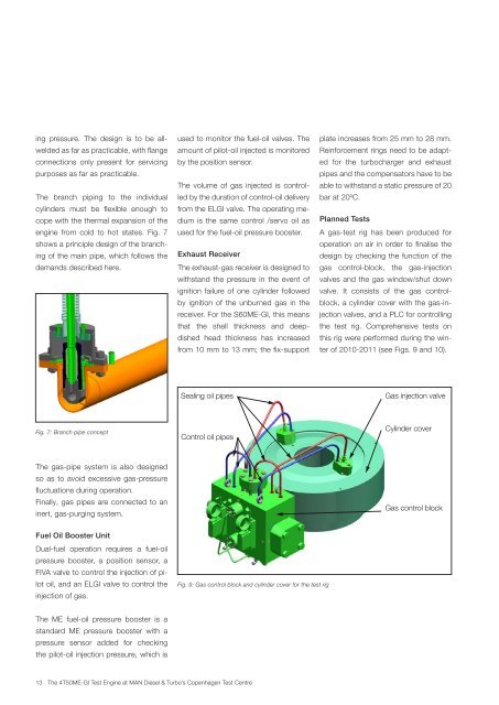
Sealing oil pipes<br />
Control oil pipes<br />
Fig. 9: Gas control block and cylinder cover for the test rig<br />
13 <strong>The</strong> <strong>4T50ME</strong>-<strong>GI</strong> <strong>Test</strong> <strong>Engine</strong> <strong>at</strong> <strong>MAN</strong> <strong>Diesel</strong> & Turbo’s Copenhagen <strong>Test</strong> Centre<br />
pl<strong>at</strong>e increases from 25 mm to 28 mm.<br />
Reinforcement rings need to be adapt-<br />
ed for the turbocharger and exhaust<br />
pipes and the compens<strong>at</strong>ors have to be<br />
able to withstand a st<strong>at</strong>ic pressure of 20<br />
bar <strong>at</strong> 20ºC.<br />
Planned <strong>Test</strong>s<br />
A gas-test rig has been produced for<br />
oper<strong>at</strong>ion on air in order to finalise the<br />
design by checking the function of the<br />
gas control-block, the gas-injection<br />
valves and the gas window/shut down<br />
valve. It consists of the gas control-<br />
block, a cylinder cover with the gas-in-<br />
jection valves, and a PLC for controlling<br />
the test rig. Comprehensive tests on<br />
this rig were performed during the win-<br />
ter of 2010-2011 (see Figs. 9 and 10).<br />
Gas injection valve<br />
Cylinder cover<br />
Gas control block