The 4T50ME-GI Test Engine at MAN Diesel & Turbo's ... - Sae.org
The 4T50ME-GI Test Engine at MAN Diesel & Turbo's ... - Sae.org
The 4T50ME-GI Test Engine at MAN Diesel & Turbo's ... - Sae.org

You also want an ePaper? Increase the reach of your titles
YUMPU automatically turns print PDFs into web optimized ePapers that Google loves.
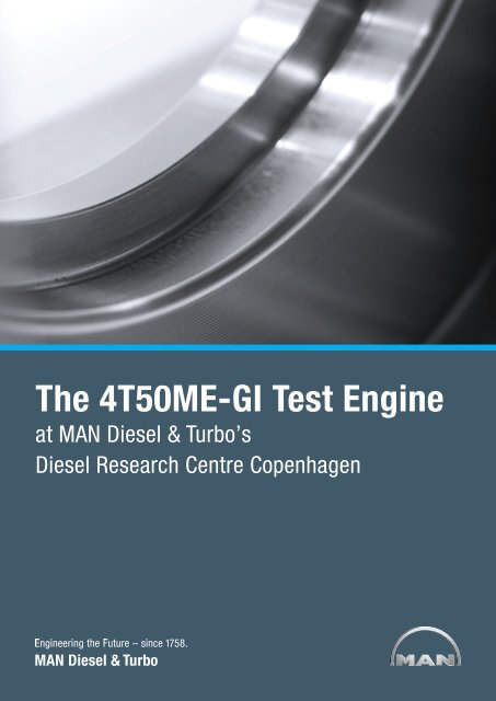
<strong>The</strong> <strong>4T50ME</strong>-<strong>GI</strong> <strong>Test</strong> <strong>Engine</strong><br />
<strong>at</strong> <strong>MAN</strong> <strong>Diesel</strong> & Turbo’s<br />
<strong>Diesel</strong> Research Centre Copenhagen
Content<br />
<strong>MAN</strong> B&W <strong>Diesel</strong><br />
1 Introduction ..............................................................................................6<br />
2 <strong>The</strong> <strong>Test</strong> Facility.........................................................................................7<br />
<strong>The</strong> research engine – <strong>4T50ME</strong>-X ............................................................7<br />
Applic<strong>at</strong>ion of the research engine ...........................................................7<br />
3 Reciproc<strong>at</strong>ing Internal Combustion <strong>Engine</strong>s on Gas Fuel ............................9<br />
4 ME-<strong>GI</strong> Concept and <strong>Engine</strong> Design ......................................................... 10<br />
Design concept ................................................................................... 10<br />
Fuel Injection Valves .............................................................................. 10<br />
Cylinder Cover ...................................................................................... 11<br />
Gas Block............................................................................................. 11<br />
Gas Pipes ............................................................................................. 12<br />
Fuel Oil Booster Unit ............................................................................. 13<br />
Exhaust Receiver .................................................................................. 13<br />
Planned <strong>Test</strong>s ....................................................................................... 13<br />
5 ME-<strong>GI</strong> gas supply system ........................................................................ 14<br />
Layout of test-bed arrangements: ......................................................... 14<br />
Cryogenic storage tank: ........................................................................ 15<br />
Cryogenic reciproc<strong>at</strong>ing pump: ............................................................. 15<br />
Vaporiser and glycol w<strong>at</strong>er he<strong>at</strong>ing system: ........................................... 15<br />
Gas-pressure control: ........................................................................... 15<br />
Gas train .............................................................................................. 16<br />
Double-wall gas pipes ........................................................................... 16<br />
N 2 purging system: ............................................................................... 17<br />
Control and safety system: .................................................................... 17<br />
6 <strong>Test</strong> Program .......................................................................................... 17<br />
7 Potential Applic<strong>at</strong>ions for ME-<strong>GI</strong> <strong>Engine</strong>s ................................................. 18<br />
Conclusion ................................................................................................. 18<br />
<strong>The</strong> <strong>4T50ME</strong>-<strong>GI</strong> <strong>Test</strong> <strong>Engine</strong> <strong>at</strong> <strong>MAN</strong> <strong>Diesel</strong> & Turbo’s Copenhagen <strong>Test</strong> Centre<br />
4
<strong>The</strong> <strong>4T50ME</strong>-<strong>GI</strong> <strong>Test</strong> <strong>Engine</strong> <strong>at</strong> <strong>MAN</strong> <strong>Diesel</strong> & Turbo’s<br />
Copenhagen <strong>Test</strong> Centre<br />
1 Introduction<br />
<strong>The</strong> commercial oper<strong>at</strong>ion of two-<br />
stroke, low-speed diesel engines us-<br />
ing n<strong>at</strong>ural gas as a fuel source aboard<br />
ships has been a dream and even an<br />
obsession for decades.<br />
<strong>The</strong> high efficiency and unrivalled relia-<br />
bility of such engines, together with the<br />
widespread availability of an onshore<br />
gas-distribution network since the<br />
1930s, triggered the development and<br />
applic<strong>at</strong>ion of such engines for power<br />
gener<strong>at</strong>ion in the United St<strong>at</strong>es.<br />
At the 1983 CIMAC congress in Paris,<br />
Mitsui <strong>Engine</strong>ering and Shipbuilding re-<br />
launched the concept by proposing a<br />
low-speed K80<strong>GI</strong>DE, also referred to as<br />
a K80MC-<strong>GI</strong>, a low-speed diesel engine<br />
based on the <strong>MAN</strong> B&W K80MC. This<br />
was adapted for high-pressure gas in-<br />
<strong>MAN</strong> B&W <strong>Diesel</strong><br />
jection (<strong>GI</strong>), and was particularly aimed<br />
<strong>at</strong> replacing the r<strong>at</strong>her energy-inefficient<br />
steam turbines used for LNG carrier<br />
propulsion.<br />
At the time, both the gas-vs-fuel price<br />
development, as well as technical and<br />
political reluctance, prevented the idea<br />
from being commercially successful.<br />
However, technically, the concept was<br />
fully proven on the test bed and, com-<br />
mercially, as a prime mover in the Chiba<br />
power plant in Japan.<br />
In more recent times, development has<br />
taken new turns with environmental<br />
consider<strong>at</strong>ions having changed from<br />
being interesting to becoming a neces-<br />
sity. Furthermore, diesel engines have<br />
now entered the propulsion market for<br />
LNG carriers en masse and gas engines<br />
are on the verge of being adopted for<br />
propulsion by other ship types.<br />
Accordingly, <strong>MAN</strong> <strong>Diesel</strong> and Turbo<br />
Denmark took the decision in 2010 to<br />
build a full-scale test and demonstr<strong>at</strong>ion<br />
engine <strong>at</strong> its R&D centre in Copenha-<br />
gen. This intends to clear the way for<br />
the full-scale commercial adoption of<br />
the now electronically-controlled, dual-<br />
fuel, low-speed, two-stroke ME-<strong>GI</strong> die-<br />
sel-engine range.<br />
This paper outlines the building of the<br />
engine, the design and layout of its gas-<br />
supply system and its test programme.<br />
It also discusses the ME-<strong>GI</strong> engine’s<br />
position in the market as one of several<br />
solutions capable of meeting the IMO’s<br />
Tier-III emission regul<strong>at</strong>ions, scheduled<br />
to come in force for newbuildings from<br />
January 1, 2016.<br />
<strong>The</strong> <strong>4T50ME</strong>-<strong>GI</strong> <strong>Test</strong> <strong>Engine</strong> <strong>at</strong> <strong>MAN</strong> <strong>Diesel</strong> & Turbo’s Copenhagen <strong>Test</strong> Centre<br />
6
2 <strong>The</strong> <strong>Test</strong> Facility<br />
<strong>The</strong> <strong>MAN</strong> <strong>Diesel</strong> & Turbo research cen-<br />
tre in Copenhagen was inaugur<strong>at</strong>ed<br />
in 1992. Its centrepiece is a specially-<br />
designed, two-stroke, four-cylinder re-<br />
search engine, which plays an impor-<br />
tant role in the development of <strong>MAN</strong><br />
B&W two-stroke diesel engines. <strong>The</strong> re-<br />
search engine has logged almost 8,500<br />
hours in oper<strong>at</strong>ion since 1992 and hosts<br />
many, different type tests, from basic<br />
research – for example, into m<strong>at</strong>erials,<br />
tribology, and combustion theory – to<br />
testing and verific<strong>at</strong>ion of engine con-<br />
trol systems and type-approval testing<br />
(TAT). In recent years, the research en-<br />
gine has also been applied on a large<br />
scale for the testing of emission-reduc-<br />
ing systems, such as EGR (exhaust gas<br />
recircul<strong>at</strong>ion) and scrubbers.<br />
In 1997, the research centre was ex-<br />
panded to include additional test rigs<br />
for the simul<strong>at</strong>ion of engine sub-com-<br />
ponents. <strong>The</strong> test rigs allow the rapid<br />
testing and development of concepts<br />
and systems in a safe environment<br />
without risking any damage to the en-<br />
gine. This ensures a certain degree of<br />
product m<strong>at</strong>uring before installing the<br />
systems on, for example, the research<br />
engine, thereby saving service time on<br />
the engine. More and more test rigs<br />
have been added over the years.<br />
<strong>The</strong> research centre was extended<br />
once again in 2010 where a third floor<br />
with new office facilities, a new engine-<br />
control room, and a new emission-<br />
measuring room was added. From the<br />
offices, the R&D engineers have direct<br />
access to the engine-control room.<br />
<strong>The</strong> research engine – <strong>4T50ME</strong>-X<br />
<strong>The</strong> research engine has four cylinders<br />
of 50-cm bore and a stroke of 2,200<br />
cm, gener<strong>at</strong>ing 7,080 kW <strong>at</strong> 123 rev./<br />
min.<br />
7 <strong>The</strong> <strong>4T50ME</strong>-<strong>GI</strong> <strong>Test</strong> <strong>Engine</strong> <strong>at</strong> <strong>MAN</strong> <strong>Diesel</strong> & Turbo’s Copenhagen <strong>Test</strong> Centre<br />
Fig. 1: <strong>MAN</strong> <strong>Diesel</strong> & Turbo research centre in Copenhagen<br />
<strong>Test</strong> engine specific<strong>at</strong>ion – <strong>4T50ME</strong>-X<br />
<strong>Engine</strong> type <strong>Diesel</strong>, two-stroke<br />
No. of cylinders 4<br />
Bore 50 mm<br />
Stroke 2,200 mm<br />
Power 7,080 kW<br />
Max. speed 123 rpm<br />
Applic<strong>at</strong>ion of the research engine<br />
<strong>The</strong> research engine is utilised for a<br />
wide range of research tests. <strong>The</strong>se<br />
tests are characterised by the fact th<strong>at</strong><br />
they cannot be carried out elsewhere,<br />
for example, on an engine-builder’s<br />
testbed or aboard a vessel in service.<br />
Furthermore, many tests require highly<br />
controlled conditions to ensure a high
eliability while the large volume of d<strong>at</strong>a<br />
typically acquired from the extensive<br />
measuring set-ups make the test centre<br />
an eminently suitable test venue.<br />
<strong>The</strong> test centre has also added spe-<br />
cial adjustment options to ensure valid<br />
measurements, for instance, the intake<br />
air temper<strong>at</strong>ure can be adjusted very<br />
precisely, for example, to enable ISO<br />
conditions.<br />
Other tests involve risks, such as pro-<br />
voked breakdowns or the testing of<br />
control failures.<br />
Fig. 2: Research engine in ME-<strong>GI</strong> configur<strong>at</strong>ion<br />
<strong>MAN</strong> B&W <strong>Diesel</strong><br />
Other examples of research tests in-<br />
clude:<br />
Oil-film measurements in bearings<br />
testing of piston rings<br />
m<strong>at</strong>erial testing, e.g. for liners<br />
SFOC / emission optimis<strong>at</strong>ion<br />
various combustion studies<br />
testing of subcomponents<br />
testing of monitoring systems and<br />
safety systems, e.g. oil mist detector<br />
emission control systems<br />
turbochargers<br />
engine control systems<br />
ECS TAT tests for class societies<br />
<strong>The</strong> test centre engine’s special desig-<br />
n<strong>at</strong>ion (ME-X) is an indic<strong>at</strong>ion of its hy-<br />
brid engine control design, which, over<br />
its lifetime, has frequently changed.<br />
Currently, the following configur<strong>at</strong>ions<br />
are possible:<br />
1. ME: 100% electronically-controlled<br />
engine with hydraulically-actu<strong>at</strong>ed<br />
exhaust valve and fuel injection.<br />
2. ME-B: electronically-controlled en-<br />
gine with hydraulically-actu<strong>at</strong>ed fuel<br />
injection and simul<strong>at</strong>ed mechanically-<br />
actu<strong>at</strong>ed exhaust valve.<br />
3. ME-<strong>GI</strong> - ME engine with Gas Injection<br />
(see Fig. 2).<br />
<strong>The</strong> <strong>4T50ME</strong>-<strong>GI</strong> <strong>Test</strong> <strong>Engine</strong> <strong>at</strong> <strong>MAN</strong> <strong>Diesel</strong> & Turbo’s Copenhagen <strong>Test</strong> Centre<br />
8
3 Reciproc<strong>at</strong>ing Internal Combustion<br />
<strong>Engine</strong>s on Gas Fuel<br />
Different principles have been used to<br />
oper<strong>at</strong>e reciproc<strong>at</strong>ing internal-com-<br />
bustion engines on gas. <strong>The</strong> two main<br />
types are:<br />
Premixed combustion in an Otto-<br />
type cycle. This principle is similar<br />
to a normal gasoline (or Otto) engine,<br />
where low-pressure gas is mixed with<br />
the fresh charge prior to entering the<br />
cylinder. <strong>The</strong> gas-air mixture then en-<br />
ters the combustion chamber and is<br />
compressed. <strong>The</strong> ignition of the mix-<br />
ture is controlled either by a spark<br />
plug <strong>at</strong> the top of the combustion<br />
chamber, by a pre-ignition chamber,<br />
or by injecting easily ignitable fuel via<br />
a separ<strong>at</strong>e pilot-fuel injection system.<br />
<strong>The</strong> gas-air mixture is subsequently<br />
burned in a pre-mixed mode and the<br />
he<strong>at</strong> release carries out its mechani-<br />
cal work on the piston. Too early<br />
self-ignition and misfire of the mixture<br />
leads to knocking th<strong>at</strong> can destroy<br />
the engine mechanically. <strong>The</strong> ignita-<br />
bility of the mixture is highly depend-<br />
ent on the mixture composition and<br />
gas species, and hence a function of<br />
the type of gaseous fuel. Since the<br />
knocking regime must be avoided<br />
with some safety margin, this effec-<br />
tively limits the possible engine com-<br />
pression r<strong>at</strong>io and maximum cylinder<br />
pressures and hereby places a limit<br />
to the obtainable energy efficiency.<br />
<strong>The</strong> <strong>Diesel</strong> Gas <strong>Engine</strong>. This fea-<br />
tures a high-pressure gas injector<br />
th<strong>at</strong> injects gas into the compressed<br />
charge. Gas and fresh, compressed<br />
air mix in the jet and burn immedi-<br />
<strong>at</strong>ely in a turbulent, non-premixed<br />
jet flame. <strong>The</strong> ignition of the mixture<br />
is usually ensured by employing a<br />
second injector for small amounts of<br />
easily ignitable fuel, such as ordinary<br />
diesel oil. <strong>The</strong> system has high fuel<br />
flexibility as all, common diesel fuels<br />
may be used from the pilot system<br />
without the use of the gas injec-<br />
tors. In gas mode, the principle is<br />
very robust for vari<strong>at</strong>ions in the gas<br />
mixture and can make use of virtu-<br />
ally any gaseous fuel. Since misfire is<br />
not possible (the gaseous fuel is in-<br />
jected when combustion has already<br />
started and not before), compression<br />
r<strong>at</strong>es and cylinder pressures are not<br />
limited by a knocking condition and<br />
hence higher energy efficiency can<br />
be obtained.<br />
Today, marine, low-speed, two-stroke,<br />
diesel engines are the de-facto stand-<br />
ard for the propulsion of commercial<br />
vessels. This is due to their straightfor-<br />
ward install<strong>at</strong>ion with a direct coupled<br />
propeller, high efficiency, ability to burn<br />
HFO, simple design, low maintenance<br />
costs and, not least, reliability.<br />
Current trends suggest th<strong>at</strong> the price<br />
of LNG per energy unit will become<br />
lower than th<strong>at</strong> of HFO and significantly<br />
lower than for MDO and MGO. Further-<br />
more, the recent, giant expansion of<br />
LNG transport worldwide will present<br />
opportunities for the establishment of<br />
LNG bunkering st<strong>at</strong>ions <strong>at</strong> str<strong>at</strong>egic lo-<br />
c<strong>at</strong>ions.<br />
<strong>The</strong> ME-<strong>GI</strong> concept, oper<strong>at</strong>ing accord-<br />
ing to the second principle of a diesel<br />
gas engine, will retain all of the previ-<br />
ously mentioned fe<strong>at</strong>ures of the two-<br />
stroke propulsion machinery and, si-<br />
9 <strong>The</strong> <strong>4T50ME</strong>-<strong>GI</strong> <strong>Test</strong> <strong>Engine</strong> <strong>at</strong> <strong>MAN</strong> <strong>Diesel</strong> & Turbo’s Copenhagen <strong>Test</strong> Centre<br />
multaneously, allow the possibility of<br />
using LNG as a fuel whenever beneficial<br />
from an economic or emission point of<br />
view.<br />
<strong>The</strong> engine designer developing a gas-<br />
injection diesel engine must develop a<br />
gas-injection system together with an<br />
additional injection system for small<br />
amounts of diesel fuel (the so-called pilot<br />
injection) in order to ensure a safe igni-<br />
tion <strong>at</strong> all oper<strong>at</strong>ing points. This requires<br />
an entirely new system for engine con-<br />
trol and monitoring th<strong>at</strong> not only needs<br />
to be designed, but also optimised for<br />
different oper<strong>at</strong>ing conditions. Due to<br />
the poor ignition properties of n<strong>at</strong>ural<br />
gas, the cylinder processes need to be<br />
monitored continuously with a system<br />
of sensors and electronics th<strong>at</strong> require<br />
calibr<strong>at</strong>ion during engine oper<strong>at</strong>ion.<br />
Furthermore, the control system must<br />
be able to deal effectively with the un-<br />
certainty of the actual gas properties<br />
to be able to continuously optimise the<br />
fuel efficiency. <strong>The</strong> lack of sulphur in the<br />
n<strong>at</strong>ural gas, although beneficial from an<br />
environmental point of view, leads to tri-<br />
bological challenges, because sulphur<br />
components generally have very good<br />
lubric<strong>at</strong>ion properties. <strong>The</strong> change of<br />
fuel to n<strong>at</strong>ural gas not only involves<br />
changes to the engine, but requires the<br />
development of guidelines and rules on<br />
how to install tank and distribution sys-<br />
tems for n<strong>at</strong>ural gas aboard ships.
4 ME-<strong>GI</strong> Concept and <strong>Engine</strong> Design<br />
Design concept<br />
<strong>The</strong> test system consists of an LNG<br />
tank, a fuel-gas supply unit th<strong>at</strong>, as is<br />
the case aboard a vessel, are loc<strong>at</strong>ed<br />
outside the building/engine room.<br />
Inside the building, the NG gas, sup-<br />
plied <strong>at</strong> a pressure of 250-300 bar<br />
and 45 deg C, is led to the cylinders<br />
through a double-wall pipe system. A<br />
gas-injection control block is mounted<br />
on each cylinder cover. In parallel with<br />
the inlet pipe, there is a similar, double-<br />
wall pipe for discharging all NG when<br />
the gas system is shut down and emp-<br />
tied by N2 purging.<br />
At all points where a gas leak from the<br />
system to the engine room could poten-<br />
tially occur, the gas is collected in a ven-<br />
til<strong>at</strong>ed buffer space which is monitored<br />
by HC sensors.<br />
Head – Gas valve<br />
Fig. 3: Gas injection valve<br />
<strong>MAN</strong> B&W <strong>Diesel</strong><br />
Housing<br />
<strong>The</strong> ME-<strong>GI</strong> concept maintains the full<br />
functionality of the existing, HFO-burn-<br />
ing, two-stroke engine. <strong>The</strong> <strong>GI</strong> system<br />
is, so to say, an add-on system giving<br />
an additional oper<strong>at</strong>ion mode where the<br />
LNG can be used as fuel simultaneously<br />
with diesel or heavy fuel oils and <strong>at</strong> al-<br />
most any r<strong>at</strong>io.<br />
In the following sections of this paper,<br />
the ME-<strong>GI</strong> system is described, starting<br />
where the gas is injected into the com-<br />
bustion space, and ending where the<br />
gas enters the engine room.<br />
Fuel Injection Valves<br />
Dual-fuel oper<strong>at</strong>ion requires valves for<br />
injection of both pilot fuel-oil and gas<br />
fuel. Two separ<strong>at</strong>e valves types are used<br />
with two fitted for gas injection and two<br />
for pilot fuel-oil. <strong>The</strong> pilot fuel-oil valve<br />
is a standard fuel-oil valve without any<br />
changes. <strong>The</strong>refore, it is also possible<br />
to run the engine <strong>at</strong> 100 % MCR on fuel<br />
oil – HFO as well as MDO.<br />
O-ring<br />
Sealing ring<br />
Spring<br />
Spindle<br />
Gas enters the gas-injection valve<br />
through bores in the cylinder cover. To<br />
prevent gas leakage between the cyl-<br />
inder cover and the gas-injection valve<br />
– as well as between the valve hous-<br />
ing and the spindle guide – sealing rings<br />
made of temper<strong>at</strong>ure- and gas-resistant<br />
m<strong>at</strong>erial are installed. Any gas leakage<br />
through the gas-sealing rings is led<br />
through bores in the gas-injection valve<br />
to the double-wall gas piping system,<br />
where any gas leakage is detected by<br />
HC sensors.<br />
<strong>The</strong> gas acts continuously on the valve<br />
spindle <strong>at</strong> a pressure of about 250-300<br />
bar. In order to prevent the gas from en-<br />
tering the control-oil activ<strong>at</strong>ing system,<br />
the spindle is sealed by means of seal-<br />
ing oil led to the spindle clearance <strong>at</strong> a<br />
pressure higher than the gas pressure<br />
(15 bar higher).<br />
Holder<br />
Spindle guide<br />
Nozzle<br />
<strong>The</strong> <strong>4T50ME</strong>-<strong>GI</strong> <strong>Test</strong> <strong>Engine</strong> <strong>at</strong> <strong>MAN</strong> <strong>Diesel</strong> & Turbo’s Copenhagen <strong>Test</strong> Centre<br />
10
Cylinder Cover<br />
<strong>The</strong> cylinder cover has a face for the<br />
mounting of the gas control-block (de-<br />
scribed further on) and is provided with<br />
a set of bores, which are for supplying<br />
gas from the gas control-block to both<br />
gas injection valves (see Fig. 4).<br />
<strong>The</strong> cylinder cover is provided with an<br />
Inconel cladding in the area with the<br />
highest thermal load.<br />
Gas injection valve<br />
Fig. 4: Cylinder cover for ME-<strong>GI</strong><br />
Gas Block<br />
<strong>The</strong> gas control-block incorpor<strong>at</strong>es an<br />
accumul<strong>at</strong>or provided with a windows/<br />
shut-down valve and two purge valves.<br />
All high-pressure gas sealings lead<br />
into spaces th<strong>at</strong> are connected to the<br />
double-wall pipe system for leakage de-<br />
tection. <strong>The</strong> gas is supplied to the ac-<br />
cumul<strong>at</strong>or via a non-return valve placed<br />
in the connection piece. From the ac-<br />
cumul<strong>at</strong>or, the gas passes through<br />
a bore in the gas control-block to the<br />
window/shut-down valve, which in the<br />
gas mode is opened and controlled by<br />
11 <strong>The</strong> <strong>4T50ME</strong>-<strong>GI</strong> <strong>Test</strong> <strong>Engine</strong> <strong>at</strong> <strong>MAN</strong> <strong>Diesel</strong> & Turbo’s Copenhagen <strong>Test</strong> Centre<br />
Face for gas block<br />
Pilot / fuel oil<br />
injection valve<br />
Indic<strong>at</strong>or valve<br />
Face for gas block<br />
the MPC. <strong>The</strong> window/shut-down valve<br />
also includes a fe<strong>at</strong>ure th<strong>at</strong> prevents<br />
gas injection in the combustion cham-<br />
ber <strong>at</strong> any inappropri<strong>at</strong>e point of the<br />
engine stroke. From the gas window/<br />
shut-down valve, the gas is led to the<br />
gas-injection valve via bores in the gas<br />
control-block and the cylinder cover.<br />
Blow-off/purge valves are designed to<br />
pressure-release the gas bores when<br />
needed, as well as to empty the accu-<br />
mul<strong>at</strong>or when the engine is no longer to<br />
oper<strong>at</strong>e in gas mode (see Fig. 5).
Gas block<br />
EL<strong>GI</strong> valve<br />
Purge & blow-off<br />
valve<br />
Fig. 5: Gas control block<br />
Fig. 6: ME-<strong>GI</strong> piping<br />
<strong>MAN</strong> B&W <strong>Diesel</strong><br />
Control<br />
valves<br />
Gas inlet<br />
O-rings<br />
Connection piece<br />
Cylinder cover<br />
Sealing rings<br />
Window / shut down valve<br />
Gas control block<br />
Gas accumul<strong>at</strong>or volume<br />
Connection pipe<br />
Non return valve<br />
Gas Pipes<br />
A common-rail (constant pressure) sys-<br />
tem is to be fitted for high-pressure gas<br />
distribution to each gas-control block.<br />
<strong>The</strong> gas pipes are designed with dou-<br />
ble walls, with the outer shielding pipe<br />
designed to prevent gas outflow to<br />
the machinery spaces in the event of<br />
the rupture of the inner gas pipe. <strong>The</strong><br />
intervening space, including also the<br />
space around valves, flanges, etc., is<br />
equipped with separ<strong>at</strong>e mechanical<br />
ventil<strong>at</strong>ion with a capacity of approx.<br />
30 air-changes per hour. <strong>The</strong> pressure<br />
in the intervening space is below th<strong>at</strong><br />
of the engine room and (extractor) fan<br />
motors are placed outside the ventila-<br />
tion ducts, and the fan m<strong>at</strong>erial must be<br />
manufactured from spark-free m<strong>at</strong>erial.<br />
<strong>The</strong> ventil<strong>at</strong>ion inlet air must be taken<br />
from a gas-safe area.<br />
<strong>The</strong> double-wall piping system is de-<br />
signed so th<strong>at</strong> every part is ventil<strong>at</strong>ed.<br />
However, tiny volumes around the gas-<br />
injection valves in the cylinder cover are<br />
not ventil<strong>at</strong>ed by flowing air for practical<br />
reasons. Small gas amounts, which in<br />
the event of leakages may accumul<strong>at</strong>e<br />
in these small clearances, blind ends,<br />
etc. cannot be avoided, but the amount<br />
of gas is negligible. Any other gas leak-<br />
ages are led to the ventil<strong>at</strong>ed part of the<br />
double-wall piping system and detect-<br />
ed by the HC sensors.<br />
<strong>The</strong> gas pipes on the engine are de-<br />
signed for a pressure 50% higher than<br />
normal working pressure, and are sup-<br />
ported to avoid mechanical vibr<strong>at</strong>ions.<br />
<strong>The</strong> gas pipes should furthermore be<br />
protected against heavy items being<br />
dropped upon them. <strong>The</strong> pipes are<br />
pressure tested <strong>at</strong> 1.5 times the work-<br />
<strong>The</strong> <strong>4T50ME</strong>-<strong>GI</strong> <strong>Test</strong> <strong>Engine</strong> <strong>at</strong> <strong>MAN</strong> <strong>Diesel</strong> & Turbo’s Copenhagen <strong>Test</strong> Centre<br />
12
ing pressure. <strong>The</strong> design is to be all-<br />
welded as far as practicable, with flange<br />
connections only present for servicing<br />
purposes as far as practicable.<br />
<strong>The</strong> branch piping to the individual<br />
cylinders must be flexible enough to<br />
cope with the thermal expansion of the<br />
engine from cold to hot st<strong>at</strong>es. Fig. 7<br />
shows a principle design of the branch-<br />
ing of the main pipe, which follows the<br />
demands described here.<br />
Fig. 7: Branch pipe concept<br />
<strong>The</strong> gas-pipe system is also designed<br />
so as to avoid excessive gas-pressure<br />
fluctu<strong>at</strong>ions during oper<strong>at</strong>ion.<br />
Finally, gas pipes are connected to an<br />
inert, gas-purging system.<br />
Fuel Oil Booster Unit<br />
Dual-fuel oper<strong>at</strong>ion requires a fuel-oil<br />
pressure booster, a position sensor, a<br />
FIVA valve to control the injection of pi-<br />
lot oil, and an EL<strong>GI</strong> valve to control the<br />
injection of gas.<br />
<strong>The</strong> ME fuel-oil pressure booster is a<br />
standard ME pressure booster with a<br />
pressure sensor added for checking<br />
the pilot-oil injection pressure, which is<br />
used to monitor the fuel-oil valves. <strong>The</strong><br />
amount of pilot-oil injected is monitored<br />
by the position sensor.<br />
<strong>The</strong> volume of gas injected is control-<br />
led by the dur<strong>at</strong>ion of control-oil delivery<br />
from the EL<strong>GI</strong> valve. <strong>The</strong> oper<strong>at</strong>ing me-<br />
dium is the same control /servo oil as<br />
used for the fuel-oil pressure booster.<br />
Exhaust Receiver<br />
<strong>The</strong> exhaust-gas receiver is designed to<br />
withstand the pressure in the event of<br />
ignition failure of one cylinder followed<br />
by ignition of the unburned gas in the<br />
receiver. For the S60ME-<strong>GI</strong>, this means<br />
th<strong>at</strong> the shell thickness and deep-<br />
dished head thickness has increased<br />
from 10 mm to 13 mm; the fix-support<br />
Sealing oil pipes<br />
Control oil pipes<br />
Fig. 9: Gas control block and cylinder cover for the test rig<br />
13 <strong>The</strong> <strong>4T50ME</strong>-<strong>GI</strong> <strong>Test</strong> <strong>Engine</strong> <strong>at</strong> <strong>MAN</strong> <strong>Diesel</strong> & Turbo’s Copenhagen <strong>Test</strong> Centre<br />
pl<strong>at</strong>e increases from 25 mm to 28 mm.<br />
Reinforcement rings need to be adapt-<br />
ed for the turbocharger and exhaust<br />
pipes and the compens<strong>at</strong>ors have to be<br />
able to withstand a st<strong>at</strong>ic pressure of 20<br />
bar <strong>at</strong> 20ºC.<br />
Planned <strong>Test</strong>s<br />
A gas-test rig has been produced for<br />
oper<strong>at</strong>ion on air in order to finalise the<br />
design by checking the function of the<br />
gas control-block, the gas-injection<br />
valves and the gas window/shut down<br />
valve. It consists of the gas control-<br />
block, a cylinder cover with the gas-in-<br />
jection valves, and a PLC for controlling<br />
the test rig. Comprehensive tests on<br />
this rig were performed during the win-<br />
ter of 2010-2011 (see Figs. 9 and 10).<br />
Gas injection valve<br />
Cylinder cover<br />
Gas control block
5 ME-<strong>GI</strong> gas supply system<br />
This is a short description of the com-<br />
ponents and systems involved in a gas-<br />
supply system based on pressurising<br />
LNG with a high-pressure, cryogenic<br />
pump and then vaporising the gas be-<br />
fore supply to the ME-<strong>GI</strong> gas-injection<br />
system.<br />
<strong>The</strong> high-pressure (n<strong>at</strong>ural) gas required<br />
by the engine can be provided by either<br />
reciproc<strong>at</strong>ing compressors working<br />
on evapor<strong>at</strong>ed gas, for example, from<br />
a pipeline, or by a cryogenic system<br />
working from an LNG network. For our<br />
purposes, the cryogenic system is most<br />
feasible.<br />
<strong>The</strong> system must be suitable for the<br />
supply of fuel to both test-bed installa-<br />
tions <strong>at</strong> an engine builder and aboard<br />
an LNG carrier with reliquefaction of<br />
BOG, as well as aboard non-LNG carri-<br />
ers with an LNG tank installed <strong>at</strong> a suit-<br />
able place in the hull.<br />
<strong>The</strong> following items are required for the<br />
ME-<strong>GI</strong> gas supply system:<br />
layout of test bed arrangements<br />
cryogenic storage tank<br />
cryogenic reciproc<strong>at</strong>ing pump<br />
vaporiser and glycol w<strong>at</strong>er-he<strong>at</strong>ing<br />
system<br />
gas-pressure control<br />
gas train<br />
double-wall gas pipes<br />
N2 purging system<br />
control and safety system<br />
Layout of test-bed arrangements:<br />
<strong>The</strong> ME-<strong>GI</strong> gas-supply system consists<br />
of a cryogenic storage tank, a high-<br />
pressure cryogenic pump, a puls<strong>at</strong>ion<br />
damper, a vaporiser and a gas-flow/<br />
<strong>MAN</strong> B&W <strong>Diesel</strong><br />
MPC unit<br />
Fig. 10: Gas test rig<br />
LNG tank<br />
27,000 l<br />
Gas (air) supply unit Cylinder cover<br />
PLC control unit<br />
High pressure pump<br />
KPL 36/80VGS1<br />
M<br />
Cool down and mini flow line<br />
Fig. 11: <strong>The</strong> ME-<strong>GI</strong> gas-supply system<br />
pressure-control system. A system de-<br />
sign could possibly look like this:<br />
<strong>The</strong> ME-<strong>GI</strong> gas-supply system should<br />
be placed outside, marked as a hazard-<br />
Control and seal oil unit<br />
Gas control block<br />
NG Damper<br />
PC PC<br />
LNG Vaporizer<br />
ME-<strong>GI</strong><br />
ous zone, and protected against poten-<br />
tial collisions.<br />
<strong>The</strong> <strong>4T50ME</strong>-<strong>GI</strong> <strong>Test</strong> <strong>Engine</strong> <strong>at</strong> <strong>MAN</strong> <strong>Diesel</strong> & Turbo’s Copenhagen <strong>Test</strong> Centre<br />
14
Fig. 12: Example of cryogenic tank design<br />
Cryogenic storage tank:<br />
<strong>The</strong> cryogenic storage tank is designed<br />
as an inner, stainless-steel vessel within<br />
an outer steel vessel. A vacuum is ap-<br />
plied between the vessels to provide<br />
sufficient insul<strong>at</strong>ion such th<strong>at</strong> it can<br />
withstand temper<strong>at</strong>ure increases over a<br />
longer period of time (up to four weeks,<br />
depending on tank pressure). <strong>The</strong> tank<br />
pressure could be 2 to 2.5 bar, depend-<br />
ing on the cryogenic-pump suction-<br />
pressure requirements. <strong>The</strong> cryogenic<br />
tank is equipped with safety valves with<br />
an opening pressure depending on de-<br />
sign layout.<br />
<strong>The</strong> cryogenic tank is supplied with<br />
LNG delivered by a lorry tanker.<br />
Cryogenic reciproc<strong>at</strong>ing pump:<br />
<strong>The</strong> cryogenic reciproc<strong>at</strong>ing pump is<br />
supplied with LNG from a storage tank<br />
connected by a vacuum-insul<strong>at</strong>ed pipe,<br />
ensuring the supply of liquefied gas. <strong>The</strong><br />
cryogenic pump could be an vacuum-<br />
insul<strong>at</strong>ed piston-pump type coupled to<br />
a variable-speed motor suitable for con-<br />
tinuous oper<strong>at</strong>ion as well as cold stand-<br />
by. A suction filter is integr<strong>at</strong>ed into the<br />
pump head. <strong>The</strong> cryogenic-pump pres-<br />
sure and flow is controlled by the vari-<br />
able-frequency pump motor. <strong>The</strong> pres-<br />
sure set-point is taken from the ME-<strong>GI</strong><br />
control system with a range from 150<br />
to 300 bar. <strong>The</strong> cryogenic pump must<br />
be equipped with a puls<strong>at</strong>ion damper in<br />
order to achieve gas-pressure fluctua-<br />
tions within 0.3 bar.<br />
Fig. 13: Gas train<br />
15 <strong>The</strong> <strong>4T50ME</strong>-<strong>GI</strong> <strong>Test</strong> <strong>Engine</strong> <strong>at</strong> <strong>MAN</strong> <strong>Diesel</strong> & Turbo’s Copenhagen <strong>Test</strong> Centre<br />
Vaporiser and glycol w<strong>at</strong>er he<strong>at</strong>ing<br />
system:<br />
<strong>The</strong> vaporiser is connected to the<br />
cryogenic-pump outlet and the LNG<br />
is he<strong>at</strong>ed with a glycol-w<strong>at</strong>er system.<br />
Altern<strong>at</strong>ive he<strong>at</strong>ing medias as engine-<br />
cooling w<strong>at</strong>er or ambient-temper<strong>at</strong>ure<br />
vaporisers could be utilised, but a gly-<br />
col-w<strong>at</strong>er he<strong>at</strong>ing system is considered<br />
to be more temper<strong>at</strong>ure-consistent. <strong>The</strong>
Fig. 14: Arrangement of double-wall piping in ventil<strong>at</strong>ion system<br />
glycol-w<strong>at</strong>er flow is constant and inde-<br />
pendent of the LNG flow r<strong>at</strong>e. <strong>The</strong> va-<br />
poriser-gas outlet temper<strong>at</strong>ure (45 °C)<br />
is controlled by the glycol-w<strong>at</strong>er tem-<br />
per<strong>at</strong>ure set-point.<br />
Gas-pressure control:<br />
<strong>The</strong> cryogenic pump is equipped with a<br />
discharge control valve. When the dis-<br />
charge control valve is open, gas flows<br />
to the vaporiser. If the gas pressure from<br />
the vaporiser outlet is higher than the<br />
gas pressure set-point from the GECU<br />
(ME-<strong>GI</strong> engine control system), the<br />
cryogenic-pump speed is decreased. If<br />
the cryogenic-pump speed reaches the<br />
minimum speed, a control valve opens<br />
to the venting mast.<br />
Gas train<br />
<strong>The</strong> gas is supplied from the vaporiser<br />
outlet through a single-wall, high-pres-<br />
sure pipe to the gas train, installed out-<br />
side the engine room, consisting of two<br />
block valves and one bleed valve (see<br />
Fig. 13).<br />
<strong>The</strong> volume between the block and<br />
bleed valves is depressurised while the<br />
gas system is out of oper<strong>at</strong>ion (block<br />
valves are closed and bleed valve<br />
open). This is a safety arrangement in<br />
<strong>MAN</strong> B&W <strong>Diesel</strong><br />
order to ensure th<strong>at</strong> no gas can unin-<br />
tentionally be supplied to the engine. A<br />
valve-leakage test is autom<strong>at</strong>ically con-<br />
ducted before gas oper<strong>at</strong>ion based on<br />
the pressure-drop over time.<br />
Double-wall gas pipes<br />
From the gas train, the gas enters the<br />
engine room and from here the gas is<br />
supplied courtesy of a double-wall pip-<br />
ing system. <strong>The</strong>se are, according to<br />
IMO guidelines, “gas-safe machinery<br />
spaces” where the engine room is main-<br />
tained as an ordinary engine room and<br />
not a hazardous area. <strong>The</strong> space be-<br />
tween the inner, high-pressure pipe and<br />
the outer pipe is continuously ventil<strong>at</strong>ed<br />
– approxim<strong>at</strong>ely 30 air changes per<br />
hour – by a mechanical ventil<strong>at</strong>or made<br />
of spark-free fan m<strong>at</strong>erial, installed out-<br />
side the engine room. <strong>The</strong> double-wall<br />
inlet must be supplied from a gas-safe<br />
area. In the event of a gas leakage from<br />
pipe rupture or sealing failure, the leak-<br />
age is detected with a HC sensor in-<br />
stalled in the ventil<strong>at</strong>ion-pipe outlet. <strong>The</strong><br />
double-wall piping should be arranged<br />
as shown in Fig. 14.<br />
<strong>The</strong> double wall ventil<strong>at</strong>ion system<br />
is also part of the engine internal gas<br />
system and every valve, gas injection<br />
valves and high pressure sealings are<br />
connected to this system. <strong>The</strong> high<br />
pressure outlet from the engine will have<br />
to be connected with a silencer of suf-<br />
ficient capacity – see Fig. 15.<br />
Fig. 15: <strong>The</strong> high-pressure engine outlet needs to be connected with a silencer of sufficient capacity<br />
<strong>The</strong> <strong>4T50ME</strong>-<strong>GI</strong> <strong>Test</strong> <strong>Engine</strong> <strong>at</strong> <strong>MAN</strong> <strong>Diesel</strong> & Turbo’s Copenhagen <strong>Test</strong> Centre<br />
16
N 2 purging system:<br />
During every gas-system depressurisa-<br />
tion, an inert-gas purging system must<br />
be connected manually or autom<strong>at</strong>ical-<br />
ly, in order to purge out remaining gas<br />
or oxygen. An additional valve before<br />
the first block valve and connected to<br />
the outlet silencer must also be installed<br />
so depressuris<strong>at</strong>ion and purging is pos-<br />
sible.<br />
Control and safety system:<br />
<strong>The</strong> ME-<strong>GI</strong> control system supplies a<br />
gas pressure set-point to the gas-sup-<br />
ply system depending on engine load,<br />
th<strong>at</strong> is, gas-pressure dynamics follow<br />
engine-load dynamics. HC sensors<br />
must be applied to the gas-supply sys-<br />
tem in order to detect leakages.<br />
Task &<br />
Schedule<br />
ME-<strong>GI</strong><br />
Development<br />
<strong>Test</strong> rig<br />
development<br />
<strong>4T50ME</strong>-<strong>GI</strong><br />
Research<br />
<strong>Engine</strong><br />
Development of<br />
Gas Injection –<br />
ECS<br />
Helios Project<br />
EU FP7<br />
7S60ME-<strong>GI</strong>8<br />
ME-<strong>GI</strong><br />
Order<br />
6 <strong>Test</strong> Program<br />
<strong>MAN</strong> <strong>Diesel</strong> & Turbo has established a<br />
comprehensive test program stretching<br />
over the next three years. Fortun<strong>at</strong>ely,<br />
the rebuilding of the test engine to ME-<br />
<strong>GI</strong> gas oper<strong>at</strong>ion will not restrict tests<br />
running on diesel fuels as the test en-<br />
gine can inherently change over be-<br />
tween the two types of fuels. <strong>Test</strong>s are<br />
planned to commence in March 2011.<br />
1. Verific<strong>at</strong>ion of test set-up<br />
2. Confirm<strong>at</strong>ion of system for basic gas<br />
oper<strong>at</strong>ion and performance tests.<br />
One very interesting target is to de-<br />
termine the lower limits for pilot-oil<br />
volume and the minimum engine-<br />
load <strong>at</strong> which the engine can oper<strong>at</strong>e<br />
in gas-burning mode.<br />
17 <strong>The</strong> <strong>4T50ME</strong>-<strong>GI</strong> <strong>Test</strong> <strong>Engine</strong> <strong>at</strong> <strong>MAN</strong> <strong>Diesel</strong> & Turbo’s Copenhagen <strong>Test</strong> Centre<br />
3. Subsequently, a series of gas param-<br />
eter tests are planned covering:<br />
emission and performance<br />
combustion optimis<strong>at</strong>ion<br />
verific<strong>at</strong>ion of Tier-II setup<br />
parameter vari<strong>at</strong>ion for Tier-III setup.<br />
Both Tier-II and Tier-III tests will be per-<br />
formed with EGR and/or WIF.<br />
<strong>The</strong> potential for CO2 and SO x emis-<br />
sions reduction by using LNG instead<br />
of HFO has garnered significant sup-<br />
port from the EU for the test program<br />
through the so-called “HELIOS” project.<br />
Year / Quarter 2009 2010 2011 2012 2013<br />
Q1 Q2 Q3 Q4 Q1 Q2 Q3 Q4 Q1 Q2 Q3 Q4 Q1 Q2 Q3 Q4 Q1 Q2 Q3 Q4<br />
ME-<strong>GI</strong> concept<br />
<strong>Test</strong> rig TS50ME-<strong>GI</strong><br />
<strong>Test</strong> Rig Start<br />
<strong>Test</strong> & Optimiz<strong>at</strong>ion<br />
Conversion <strong>4T50ME</strong>-<strong>GI</strong><br />
Decision full Scale <strong>Test</strong><br />
Agreement DSME<br />
Agreement HHIEMD<br />
Gas Injection & <strong>Engine</strong> Control System; <strong>GI</strong>-ECS<br />
Prepar<strong>at</strong>ion<br />
Design Order (DSO)<br />
Evalu<strong>at</strong>ion<br />
QG Letter of intent<br />
Applic<strong>at</strong>ion<br />
Full grant obtained<br />
Fig. 16: A Gant diagram showing the test program for a retrofit conversion to LNG-<br />
Cont.<br />
Tier II <strong>Test</strong> Cont. Tier III <strong>Test</strong><br />
<strong>Engine</strong> Start Tier II verifik<strong>at</strong>ion<br />
Customer Demonstr<strong>at</strong>ion<br />
Start integr<strong>at</strong>ion test <strong>4T50ME</strong>-<strong>GI</strong><br />
First Order ME-<strong>GI</strong><br />
QG Order Yes/No<br />
Execution<br />
Cont.<br />
Tier III<br />
verifik<strong>at</strong>ion<br />
ME-<strong>GI</strong> retrofit (46x 2x6/7S70ME-<strong>GI</strong>)
7 Potential Applic<strong>at</strong>ions for ME-<strong>GI</strong><br />
<strong>Engine</strong>s<br />
As previously mentioned, the ME-<strong>GI</strong><br />
engines – originally design<strong>at</strong>ed MC-<strong>GI</strong><br />
– were developed for LNG carrier pro-<br />
pulsion. In the project phase, the ME-<strong>GI</strong><br />
was recommended for the now-famous<br />
45-strong Q<strong>at</strong>argas fleet of Q-Flex and<br />
Q-Max LNG carriers built for the mas-<br />
sive expansion of gas export<strong>at</strong>ion from<br />
Q<strong>at</strong>ar in the Persian Gulf.<br />
However, the shipowner selected<br />
the heavy fuel variant and, accord-<br />
ingly, each of these vessels has 2 × 6<br />
7S70ME-C HFO engines installed. In<br />
the meantime, the rel<strong>at</strong>ive pricing of gas<br />
and fuel has changed in some parts of<br />
the world and a retrofit project is now in<br />
the shaping, with some of these vessels<br />
as candid<strong>at</strong>es for retrofit to 2 x 6 type<br />
7S70ME-<strong>GI</strong>.<br />
<strong>The</strong>se vessels already have a relique-<br />
faction plant on board so therefore the<br />
gas-supply train to the engines fe<strong>at</strong>ures<br />
a cryogenic pump/evapor<strong>at</strong>or. It is es-<br />
tim<strong>at</strong>ed th<strong>at</strong> such a retrofit install<strong>at</strong>ion<br />
would take about one year to prepare,<br />
followed by 4 - 6 weeks re-building,<br />
which typically would take place during<br />
a regular survey docking. Fig. 16 shows<br />
a Gant diagram for such a conversion.<br />
<strong>The</strong> ME-<strong>GI</strong> engine can also be seen as<br />
a way of simultaneously meeting Tier-III<br />
emission limits and fuel-sulphur con-<br />
tents/SO x emission limits. With n<strong>at</strong>ural<br />
gas being sulphur free, SO x emissions<br />
from an ME-<strong>GI</strong> engine are limited to th<strong>at</strong><br />
emitted by the burning of pilot oil.<br />
<strong>The</strong> extremely low SO x emissions from<br />
an ME-<strong>GI</strong> engine also facilit<strong>at</strong>e the nec-<br />
<strong>MAN</strong> B&W <strong>Diesel</strong><br />
essary Tier-III NO x control ab<strong>at</strong>ement<br />
methods for two-stroke engines, SCR<br />
( Selective C<strong>at</strong>alytic Reduction ) and<br />
EGR (Exhaust Gas Recircul<strong>at</strong>ion ). For<br />
SCR, the SO x in the exhaust limits the<br />
temper<strong>at</strong>ure regime in which the reac-<br />
tion can take place while for EGR, the<br />
exhaust gas to be recircul<strong>at</strong>ed needs to<br />
be cleaned and cooled before returning<br />
to the engine. This is obviously much<br />
cleaner when derived from an ME-<strong>GI</strong><br />
combustion. <strong>The</strong>refore, an ME-<strong>GI</strong> en-<br />
gine with SCR or EGR could constitute<br />
a Tier-III, low-speed engine as an alter-<br />
n<strong>at</strong>ive to an ME-type HFO engine with<br />
SCR or EGR and SO X scrubber.<br />
<strong>The</strong> fact th<strong>at</strong> n<strong>at</strong>ural gas is generally<br />
cheaper than HFO on a calorific input<br />
basis, while low-sulphur or even sul-<br />
phur-free fuels are significantly more ex-<br />
pensive than HFO, supports the use of<br />
ME-<strong>GI</strong> engines.<br />
<strong>The</strong> regul<strong>at</strong>ory environment is practical-<br />
ly in order already and the logistics for<br />
running on gas will come with demand.<br />
Accordingly, advanced shipbuilders –<br />
particularly in Japan and Korea – are<br />
already marketing containerships, tank-<br />
ers and bulk carriers powered by ME-<br />
<strong>GI</strong> engines. Bringing development one<br />
step further, <strong>MAN</strong> <strong>Diesel</strong> &Turbo has<br />
recently also decided to advoc<strong>at</strong>e the<br />
use of LPG and other VOCs (Vol<strong>at</strong>ile<br />
Organic Compounds) in a variant of the<br />
ME-<strong>GI</strong> engine. This will be design<strong>at</strong>ed<br />
ME-L<strong>GI</strong> (for Liquid Gas Injection). While<br />
the ME-<strong>GI</strong> probably will be used mostly<br />
in larger vessels on longer routes, the<br />
ME-L<strong>GI</strong> will be used more predomi-<br />
nantly in short-sea shipping due to the<br />
easier logistics offered by LPG/VOC.<br />
Conclusion<br />
<strong>The</strong>re is plenty of gas available in the<br />
world, with some sources evalu<strong>at</strong>ing its<br />
reserves as even gre<strong>at</strong>er than oil. <strong>The</strong><br />
main drivers for using gas <strong>at</strong> sea are<br />
first and foremost environmental con-<br />
sider<strong>at</strong>ions – including a gre<strong>at</strong> reduction<br />
in CO2 emissions – but the cost of the<br />
various fuel types are also an important<br />
factor. <strong>MAN</strong> <strong>Diesel</strong> & Turbo sees gre<strong>at</strong><br />
potential in the use of gas aboard ships<br />
and is alloc<strong>at</strong>ing substantial research<br />
efforts towards developing suitable<br />
technologies to this end.<br />
<strong>The</strong> <strong>4T50ME</strong>-<strong>GI</strong> <strong>Test</strong> <strong>Engine</strong> <strong>at</strong> <strong>MAN</strong> <strong>Diesel</strong> & Turbo’s Copenhagen <strong>Test</strong> Centre<br />
18
19 <strong>The</strong> <strong>4T50ME</strong>-<strong>GI</strong> <strong>Test</strong> <strong>Engine</strong> <strong>at</strong> <strong>MAN</strong> <strong>Diesel</strong> & Turbo’s Copenhagen <strong>Test</strong> Centre
<strong>MAN</strong> B&W <strong>Diesel</strong><br />
<strong>The</strong> <strong>4T50ME</strong>-<strong>GI</strong> <strong>Test</strong> <strong>Engine</strong> <strong>at</strong> <strong>MAN</strong> <strong>Diesel</strong> & Turbo’s Copenhagen <strong>Test</strong> Centre<br />
20
21 <strong>The</strong> <strong>4T50ME</strong>-<strong>GI</strong> <strong>Test</strong> <strong>Engine</strong> <strong>at</strong> <strong>MAN</strong> <strong>Diesel</strong> & Turbo’s Copenhagen <strong>Test</strong> Centre
<strong>MAN</strong> <strong>Diesel</strong> & Turbo<br />
Teglholmsgade 41<br />
2450 Copenhagen SV, Denmark<br />
Phone +45 33 85 11 00<br />
Fax +45 33 85 10 30<br />
info-cph@mandieselturbo.com<br />
www.mandieselturbo.com<br />
Copyright © <strong>MAN</strong> <strong>Diesel</strong> & Turbo · Subject to modific<strong>at</strong>ion in the interest of technical progress.<br />
5510-0107-00ppr Feb 2011 Printed in Denmark