Hilti HIT-CT 1 with HIT-V - Motek
Hilti HIT-CT 1 with HIT-V - Motek
Hilti HIT-CT 1 with HIT-V - Motek

You also want an ePaper? Increase the reach of your titles
YUMPU automatically turns print PDFs into web optimized ePapers that Google loves.
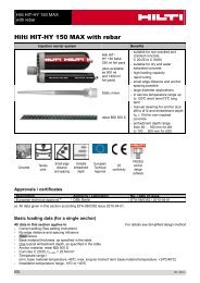
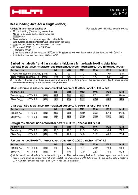
Basic loading data (for a single anchor)<br />
09 / 2012<br />
<strong>Hilti</strong> <strong>HIT</strong>-<strong>CT</strong> 1<br />
<strong>with</strong> <strong>HIT</strong>-V<br />
All data in this section applies to For details see Simplified design method<br />
- Correct setting (See setting instruction)<br />
- No edge distance and spacing influence<br />
- Steel failure<br />
- Base material thickness, as specified in the table<br />
- One typical embedment depth, as specified in the table<br />
- One anchor material, as specified in the tables<br />
- Concrete C 20/25, fck,cube = 25 N/mm²<br />
- Temperate range I<br />
(min. base material temperature -40°C, max. long ter m/short term base material temperature: +24°C/40°C)<br />
- Installation temperature range -5°C to +40°C<br />
Embedment depth a) and base material thickness for the basic loading data. Mean<br />
ultimate resistance, characteristic resistance, design resistance, recommended loads.<br />
Anchor size M8 M10 M12 M16 M20 M24<br />
Typical embedment depth hef [mm] 80 90 110 130 170 210<br />
Base material thickness h [mm] 110 120 140 170 220 270<br />
a) The allowed range of embedment depth is shown in the setting details. The corresponding load values can be<br />
calculated according to the simplified design method.<br />
Mean ultimate resistance: non-cracked concrete C 20/25 , anchor <strong>HIT</strong>-V 5.8<br />
Anchor size M8 M10 M12 M16 M20 M24<br />
Tensile NRu,m <strong>HIT</strong>-V 5.8 [kN] 18,9 30,5 44,1 87,1 135,3 190,0<br />
Shear VRu,m <strong>HIT</strong>-V 5.8 [kN] 9,5 15,8 22,1 41,0 64,1 92,4<br />
Characteristic resistance: non-cracked concrete C 20/25 , anchor <strong>HIT</strong>-V 5.8<br />
Anchor size M8 M10 M12 M16 M20 M24<br />
Tensile NRk <strong>HIT</strong>-V 5.8 [kN] 18,0 29,0 42,0 65,3 101,5 142,5<br />
Shear VRk <strong>HIT</strong>-V 5.8 [kN] 9,0 15,0 21,0 39,0 61,0 88,0<br />
Design resistance: non-cracked concrete C 20/25 , anchor <strong>HIT</strong>-V 5.8<br />
Anchor size M8 M10 M12 M16 M20 M24<br />
Tensile NRd <strong>HIT</strong>-V 5.8 [kN] 12,0 17,3 25,3 36,3 56,4 79,2<br />
Shear VRd <strong>HIT</strong>-V 5.8 [kN] 7,2 12,0 16,8 31,2 48,8 70,4<br />
Recommended loads a) : non-cracked concrete C 20/25 , anchor <strong>HIT</strong>-V 5.8<br />
Anchor size M8 M10 M12 M16 M20 M24<br />
Tensile Nrec <strong>HIT</strong>-V 5.8 [kN] 8,6 12,3 18,1 25,9 40,3 56,5<br />
Shear Vrec <strong>HIT</strong>-V 5.8 [kN] 5,1 8,6 12,0 22,3 34,9 50,3<br />
a) With overall partial safety factor for action γ = 1,4. The partial safety factors for action depend on the type of<br />
loading and shall be taken from national regulations. According ETAG 001, annex C, the partial safety factor is<br />
γG = 1,35 for permanent actions and γQ = 1,5 for variable actions.<br />
617