HVU with HIS-(R)N adhesive anchor - Motek
HVU with HIS-(R)N adhesive anchor - Motek
HVU with HIS-(R)N adhesive anchor - Motek

Create successful ePaper yourself
Turn your PDF publications into a flip-book with our unique Google optimized e-Paper software.
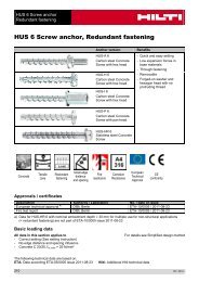
<strong>HVU</strong> <strong>with</strong> <strong>HIS</strong>-(R)N sleeve<br />
Adhesive <strong>anchor</strong><br />
<strong>HVU</strong> <strong>with</strong> <strong>HIS</strong>-(R)N <strong>adhesive</strong> <strong>anchor</strong><br />
Mortar system<br />
Benefits<br />
Hilti<br />
<strong>HVU</strong> foil capsule<br />
<strong>HIS</strong>-(R)N sleeve<br />
- suitable for non-cracked concrete<br />
C 20/25 to C 50/60<br />
- high loading capacity<br />
- suitable for dry and water<br />
saturated concrete<br />
Concrete<br />
Small edge<br />
distance<br />
and spacing<br />
Fire<br />
resistance<br />
Corrosion<br />
resistance<br />
European<br />
Technical<br />
Approval<br />
CE<br />
conformity<br />
PROFIS<br />
Anchor<br />
design<br />
software<br />
Approvals / certificates<br />
Description Authority / Laboratory No. / date of issue<br />
European technical approval a) DIBt, Berlin ETA-05/0255 / 2011-06-23<br />
Fire test report IBMB, Braunschweig UB-3333/0891-1 / 2004-03-26<br />
Assessment report (fire) warringtonfire WF 166402 / 2007-10-26<br />
a) All data given in this section according ETA-05/0255, issue 2011-06-23.<br />
Basic loading data (for a single <strong>anchor</strong>)<br />
All data in this section applies to<br />
For details see Simplified design method<br />
- Correct setting (See setting instruction)<br />
- No edge distance and spacing influence<br />
- Steel failure<br />
- Screw strength class 8.8<br />
- Base material thickness, as specified in the table<br />
- One typical embedment depth, as specified in the table<br />
- One <strong>anchor</strong> material, as specified in the tables<br />
- Concrete C 20/25, f ck,cube = 25 N/mm²<br />
- Temperate range I<br />
(min. base material temperature -40°C, max. long ter m/short term base material temperature: +24°C/40°C)<br />
- Installation temperature range -5°C to +40°C<br />
Embedment depth and base material thickness for the basic loading data.<br />
Mean ultimate resistance, characteristic resistance, design resistance, recommended<br />
loads.<br />
Anchor size M8 M10 M12 M16 M20<br />
Embedment depth [mm] 90 110 125 170 205<br />
Base material thickness [mm] 120 150 180 250 350<br />
372<br />
09 / 2012
<strong>HVU</strong> <strong>with</strong> <strong>HIS</strong>-(R)N sleeve<br />
Adhesive <strong>anchor</strong><br />
Mean ultimate resistance: concrete C 20/25 – f ck,cube = 25 N/mm², <strong>anchor</strong> <strong>HIS</strong>-N<br />
Data according ETA-05/0255, issue 2011-06-23<br />
Anchor size M8 M10 M12 M16 M20<br />
Tensile N Ru,m <strong>HIS</strong>-N [kN] 26,3 48,3 70,4 123,9 114,5<br />
Shear V Ru,m <strong>HIS</strong>-N [kN] 13,7 24,2 41,0 62,0 57,8<br />
Characteristic resistance: concrete C 20/25 – f ck,cube = 25 N/mm², <strong>anchor</strong> <strong>HIS</strong>-N<br />
Data according ETA-05/0255, issue 2011-06-23<br />
Anchor size M8 M10 M12 M16 M20<br />
Tensile N Rk <strong>HIS</strong>-N [kN] 25,0 40,0 60,0 95,0 109,0<br />
Shear V Rk <strong>HIS</strong>-N [kN] 13,0 23,0 39,0 59,0 55,0<br />
Design resistance: concrete C 20/25 – f ck,cube = 25 N/mm², <strong>anchor</strong> <strong>HIS</strong>-N<br />
Data according ETA-05/0255, issue 2011-06-23<br />
Anchor size M8 M10 M12 M16 M20<br />
Tensile N Rd <strong>HIS</strong>-N [kN] 16,7 26,7 40,0 63,3 74,1<br />
Shear V Rd <strong>HIS</strong>-N [kN] 10,4 18,4 26,0 39,3 36,7<br />
Recommended loads a) : concrete C 20/25 – f ck,cube = 25 N/mm², <strong>anchor</strong> <strong>HIS</strong>-N<br />
Data according ETA-05/0255, issue 2011-06-23<br />
Anchor size M8 M10 M12 M16 M20<br />
Tensile N rec <strong>HIS</strong>-N [kN] 11,9 19,0 28,6 45,2 53,0<br />
Shear V rec <strong>HIS</strong>-N [kN] 7,4 13,1 18,6 28,1 26,2<br />
a) With overall partial safety factor for action γ = 1,4. The partial safety factors for action depend on the type of<br />
loading and shall be taken from national regulations.<br />
Service temperature range<br />
Hilti <strong>HVU</strong> <strong>adhesive</strong> may be applied in the temperature ranges given below. An elevated base material temperature<br />
may lead to a reduction of the design bond resistance.<br />
Temperature range<br />
Base material<br />
temperature<br />
Maximum long term<br />
base material<br />
temperature<br />
Maximum short term<br />
base material<br />
temperature<br />
Temperature range I -40 °C to +40 °C +24 °C +40 °C<br />
Temperature range II -40 °C to +80 °C +50 °C +80 °C<br />
Temperature range III -40 °C to +120 °C +72 °C +120 °C<br />
Max short term base material temperature<br />
Short-term elevated base material temperatures are those that occur over brief intervals, e.g. as a result of<br />
diurnal cycling.<br />
Max long term base material temperature<br />
Long-term elevated base material temperatures are roughly constant over significant periods of time.<br />
09 / 2012 373
<strong>HVU</strong> <strong>with</strong> <strong>HIS</strong>-(R)N sleeve<br />
Adhesive <strong>anchor</strong><br />
Materials<br />
Mechanical properties of <strong>HIS</strong>-(R)N<br />
Data according ETA-05/0255, issue 2011-06-23<br />
Anchor size M8 M10 M12 M16 M20<br />
Nominal<br />
tensile<br />
strength f uk<br />
Yield<br />
strength f yk<br />
Stressed<br />
crosssection<br />
A s<br />
Moment of<br />
resistance W<br />
Material quality<br />
<strong>HIS</strong>-N [N/mm²] 490 490 460 460 460<br />
Screw 8.8 [N/mm²] 800 800 800 800 800<br />
<strong>HIS</strong>-RN [N/mm²] 700 700 700 700 700<br />
Screw A4-70 [N/mm²] 700 700 700 700 700<br />
<strong>HIS</strong>-N [N/mm²] 410 410 375 375 375<br />
Screw 8.8 [N/mm²] 640 640 640 640 640<br />
<strong>HIS</strong>-RN [N/mm²] 350 350 350 350 350<br />
Screw A4-70 [N/mm²] 450 450 450 450 450<br />
<strong>HIS</strong>-(R)N [mm²] 51,5 108,0 169,1 256,1 237,6<br />
Screw [mm²] 36,6 58 84,3 157 245<br />
<strong>HIS</strong>-(R)N [mm³] 145 430 840 1595 1543<br />
Screw [mm³] 31,2 62,3 109 277 541<br />
Part<br />
Material<br />
internally threaded sleeves a)<br />
<strong>HIS</strong>-N<br />
C-steel 1.0718,<br />
steel galvanized ≥ 5µm<br />
internally threaded sleeves b)<br />
<strong>HIS</strong>-RN<br />
stainless steel 1.4401 and 1.4571<br />
a) related fastening screw: strength class 8.8, A5 > 8% Ductile<br />
steel galvanized ≥ 5µm<br />
b) related fastening screw: strength class 70, A5 > 8% Ductile<br />
stainless steel 1.4401; 1.4404; 1.4578; 1.4571; 1.4439; 1.4362<br />
Anchor dimensions<br />
Anchor size M8 M10 M12 M16 M20<br />
Internal sleeve <strong>HIS</strong>-(R)N M8x90 M10x110 M12x125 M16x170 M20x205<br />
Anchor embedment depth [mm] 90 110 125 170 205<br />
Setting<br />
installation equipment<br />
Anchor size M8 M10 M12 M16 M20<br />
Rotary hammer TE2 – TE16 TE40 – TE70<br />
Other tools<br />
blow out pump or compressed air gun, setting tools<br />
374<br />
09 / 2012
<strong>HVU</strong> <strong>with</strong> <strong>HIS</strong>-(R)N sleeve<br />
Adhesive <strong>anchor</strong><br />
Setting instruction<br />
Dry and water-saturated concrete, hammer drilling<br />
For detailed information on installation see instruction for use given <strong>with</strong> the package of the product.<br />
For technical data for <strong>anchor</strong>s in diamond drilled holes please contact the Hilti Technical advisory service.<br />
Curing time for general conditions<br />
Data according ETA-05/0255, issue 2011-06-23<br />
Temperature<br />
of the base material<br />
Curing time before <strong>anchor</strong><br />
can be fully loaded t cure<br />
20 °C to 40 °C 20 min<br />
10 °C to 19 °C 30 min<br />
0 °C to 9 °C 1 h<br />
-5 °C to - 1 °C 5 h<br />
09 / 2012 375
<strong>HVU</strong> <strong>with</strong> <strong>HIS</strong>-(R)N sleeve<br />
Adhesive <strong>anchor</strong><br />
Setting details<br />
Sleeve <strong>HIS</strong>-(R)N<br />
Anchor size<br />
foil capsule<br />
Nominal diameter of<br />
drill bit<br />
M8x90<br />
M10x90<br />
Data according ETA-05/0255, issue 2011-06-23<br />
M10x110<br />
M12x110<br />
M12x125<br />
M16x125<br />
M16x170<br />
M20x170<br />
M20x205<br />
M24x210<br />
d 0 [mm] 14 18 22 28 32<br />
Diameter of element d [mm] 12,5 16,5 20,5 25,4 27,6<br />
Effective <strong>anchor</strong>age<br />
and drill hole depth<br />
h ef [mm] 90 110 125 170 205<br />
Minimum base<br />
material thickness<br />
h min [mm] 120 150 170 230 270<br />
Diameter of clearance<br />
hole in the fixture<br />
d f [mm] 9 12 14 18 22<br />
Thread engagement<br />
length; min - max<br />
h s [mm] 8-20 10-25 12-30 16-40 20-50<br />
Minimum spacing s min [mm] 40 45 60 80 125<br />
Minimum edge<br />
distance<br />
c min [mm] 40 45 60 80 125<br />
Critical spacing for<br />
splitting failure<br />
s cr,sp<br />
2 c cr,sp<br />
1,0 ⋅ h ef for h / h ef ≥ 2,0<br />
Critical edge distance<br />
for splitting failure a) c cr,sp [mm]<br />
4,6 h ef - 1,8 h for 2,0 > h / h ef > 1,3<br />
2,26 h ef for h / h ef ≤ 1,3<br />
Critical spacing for<br />
concrete cone failure<br />
s cr,N<br />
2 c cr,N<br />
Critical edge distance for<br />
concrete cone failure<br />
c cr,N<br />
1,5 h ef<br />
Torque moment b) T max [Nm] 10 20 40 80 150<br />
For spacing (edge distance) smaller than critical spacing (critical edge distance) the design loads have to be<br />
reduced.<br />
a) h: base material thickness (h ≥ h min )<br />
b) This is the maximum recommended torque moment to avoid splitting failure during installation for <strong>anchor</strong>s <strong>with</strong><br />
minimum spacing and/or edge distance.<br />
Simplified design method<br />
Simplified version of the design method according EOTA Technical Report TR 029. Design resistance according<br />
data given in ETA-05/0255, issue 2011-06-23.<br />
Influence of concrete strength<br />
Influence of edge distance<br />
Influence of spacing<br />
376<br />
09 / 2012
<strong>HVU</strong> <strong>with</strong> <strong>HIS</strong>-(R)N sleeve<br />
Adhesive <strong>anchor</strong><br />
<br />
Valid for a group of two <strong>anchor</strong>s. (The method may also be applied for <strong>anchor</strong> groups <strong>with</strong> more than two<br />
<strong>anchor</strong>s or more than one edge distance. The influencing factors must then be considered for each edge<br />
distance and spacing. The calculated design loads are then on the save side: They will be lower than the<br />
exact values according EOTA Technical Report TR 029. To avoid this, it is recommended to use the<br />
<strong>anchor</strong> design software PROFIS <strong>anchor</strong>)<br />
The design method is based on the following simplification:<br />
No different loads are acting on individual <strong>anchor</strong>s (no eccentricity)<br />
The values are valid for one <strong>anchor</strong>.<br />
For more complex fastening applications please use the <strong>anchor</strong> design software PROFIS Anchor.<br />
Tension loading<br />
The design tensile resistance is the lower value of<br />
- Steel resistance: N Rd,s<br />
- Combined pull-out and concrete cone resistance:<br />
N Rd,p = N 0 Rd,p ⋅ f B,p ⋅ f h,p<br />
- Concrete cone resistance: N Rd,c = N 0 Rd,c ⋅ f B ⋅ f 1,N ⋅ f 2,N ⋅ f 3,N ⋅ f h,N ⋅ f re,N<br />
- Concrete splitting resistance (only non-cracked concrete):<br />
N Rd,sp = N 0 Rd,c ⋅ f B ⋅ f 1,sp ⋅ f 2,sp ⋅ f 3,sp ⋅ f h,sp ⋅ f re,N<br />
Basic design tensile resistance<br />
Design steel resistance N Rd,s<br />
Data according ETA-05/0255, issue 2011-06-23<br />
Anchor size M8 M10 M12 M16 M20<br />
<strong>HIS</strong>-N [kN] 17,5 30,7 44,7 80,3 74,1<br />
N Rd,s<br />
<strong>HIS</strong>-RN [kN] 13,9 21,9 31,6 58,8 69,2<br />
Design combined pull-out and concrete cone resistance N Rd,p = N 0 Rd,p ⋅ f B,p ⋅ f h,p<br />
Data according ETA-05/0255, issue 2011-06-23<br />
Anchor size M8 M10 M12 M16 M20<br />
Embedment depth<br />
h ef [mm]<br />
90 110 125 170 205<br />
N 0 Rd,p Temperature range I [kN] 16,7 26,7 40,0 63,3 93,3<br />
N 0 Rd,p Temperature range II [kN] 13,3 23,3 33,3 50,0 63,3<br />
N 0 Rd,p Temperature range III [kN] 6,0 10,7 13,3 26,7 33,3<br />
Design concrete cone resistance N Rd,c = N 0 Rd,c ⋅ f B ⋅ f 1,N ⋅ f 2,N ⋅ f 3,N ⋅ f h,N ⋅ f re,N<br />
Design splitting resistance a) N Rd,sp = N 0 Rd,c ⋅ f B ⋅ f h,N ⋅ f 1,sp ⋅ f 2,sp ⋅ f 3,sp ⋅ f re,N<br />
Data according ETA-05/0255, issue 2011-06-23<br />
Anchor size M8 M10 M12 M16 M20<br />
N 0 Rd,c [kN] 28,7 38,8 47,1 74,6 98,8<br />
a) Splitting resistance must only be considered for non-cracked concrete<br />
09 / 2012 377
<strong>HVU</strong> <strong>with</strong> <strong>HIS</strong>-(R)N sleeve<br />
Adhesive <strong>anchor</strong><br />
Influencing factors<br />
Influence of concrete strength on combined pull-out and concrete cone resistance<br />
Concrete strength designation<br />
(ENV 206)<br />
C 20/25 C 25/30 C 30/37 C 35/45 C 40/50 C 45/55 C 50/60<br />
f B,p = (f ck,cube /25N/mm²) 0,28 a) 1 1,05 1,12 1,18 1,21 1,25 1,28<br />
a) f ck,cube = concrete compressive strength, measured on cubes <strong>with</strong> 150 mm side length<br />
Influence of embedment depth on combined pull-out and concrete cone resistance<br />
f h,p = 1<br />
Influence of concrete strength on concrete cone resistance<br />
Concrete strength designation<br />
(ENV 206)<br />
C 20/25 C 25/30 C 30/37 C 35/45 C 40/50 C 45/55 C 50/60<br />
f B = (f ck,cube /25N/mm²) 1/2 a) 1 1,1 1,22 1,34 1,41 1,48 1,55<br />
a) f ck,cube = concrete compressive strength, measured on cubes <strong>with</strong> 150 mm side length<br />
Influence of edge distance a)<br />
c/c cr,N<br />
c/c cr,sp<br />
f 1,N = 0,7 + 0,3⋅c/c cr,N<br />
f 1,sp = 0,7 + 0,3⋅c/c cr,sp<br />
0,1 0,2 0,3 0,4 0,5 0,6 0,7 0,8 0,9 1<br />
0,73 0,76 0,79 0,82 0,85 0,88 0,91 0,94 0,97 1<br />
f 2,N = 0,5⋅(1 + c/c cr,N )<br />
0,55 0,60 0,65 0,70 0,75 0,80 0,85 0,90 0,95 1<br />
f 2,sp = 0,5⋅(1 + c/c cr,sp )<br />
a) The the edge distance shall not be smaller than the minimum edge distance c min given in the table <strong>with</strong> the<br />
setting details. These influencing factors must be considered for every edge distance smaller than the critical<br />
edge distance.<br />
Influence of <strong>anchor</strong> spacing a)<br />
s/s cr,N<br />
s/s cr,sp<br />
0,1 0,2 0,3 0,4 0,5 0,6 0,7 0,8 0,9 1<br />
f 3,N = 0,5⋅(1 + s/s cr,N )<br />
0,55 0,60 0,65 0,70 0,75 0,80 0,85 0,90 0,95 1<br />
f 3,sp = 0,5⋅(1 + s/s cr,sp )<br />
a) The <strong>anchor</strong> spacing shall not be smaller than the minimum <strong>anchor</strong> spacing s min given in the table <strong>with</strong> the<br />
setting details. This influencing factor must be considered for every <strong>anchor</strong> spacing.<br />
Influence of embedment depth on concrete cone resistance<br />
Influence of reinforcement<br />
f h,N = 1<br />
h ef [mm] 80 90 ≥ 100<br />
f re,N = 0,5 + h ef /200mm ≤ 1 0,9 a) 0,95 a) 1<br />
a) This factor applies only for dense reinforcement. If in the area of <strong>anchor</strong>age there is reinforcement <strong>with</strong> a<br />
spacing ≥ 150 mm (any diameter) or <strong>with</strong> a diameter ≤ 10 mm and a spacing ≥ 100 mm, then a factor f re = 1<br />
may be applied.<br />
378<br />
09 / 2012
<strong>HVU</strong> <strong>with</strong> <strong>HIS</strong>-(R)N sleeve<br />
Adhesive <strong>anchor</strong><br />
Shear loading<br />
The design shear resistance is the lower value of<br />
- Steel resistance: V Rd,s<br />
- Concrete pryout resistance: V Rd,cp = k ⋅ lower value of N Rd,p and N Rd,c<br />
- Concrete edge resistance: V Rd,c = V 0 Rd,c ⋅ f B ⋅ f ß ⋅ f h ⋅ f 4<br />
Basic design shear resistance<br />
Design steel resistance V Rd,s<br />
Data according ETA-05/0255, issue 2011-06-23<br />
Anchor size M8 M10 M12 M16 M20<br />
<strong>HIS</strong>-N [kN] 10,4 18,4 26,0 39,3 36,7<br />
V Rd,s<br />
<strong>HIS</strong>-RN [kN] 8,3 12,8 19,2 35,3 41,5<br />
Design concrete pryout resistance V Rd,cp = k ⋅ N Rd,c<br />
a)<br />
Anchor size M8 M10 M12 M16 M20<br />
k 2<br />
a) N Rd,c : Design concrete cone resistance<br />
Design concrete edge resistance V Rd,c<br />
= V 0 Rd,c ⋅ f B ⋅ f ß ⋅ f h ⋅ f 4 ⋅ f hef ⋅ f c<br />
Anchor size M8 M10 M12 M16 M20<br />
V 0 Rd,c [kN] 12,4 19,8 28,4 40,7 46,8<br />
a) For <strong>anchor</strong> groups only the <strong>anchor</strong>s close to the edge must be considered.<br />
Influencing factors<br />
Influence of concrete strength<br />
Concrete strength designation<br />
(ENV 206)<br />
C 20/25 C 25/30 C 30/37 C 35/45 C 40/50 C 45/55 C 50/60<br />
f B = (f ck,cube /25N/mm²) 1/2 a) 1 1,1 1,22 1,34 1,41 1,48 1,55<br />
a) f ck,cube = concrete compressive strength, measured on cubes <strong>with</strong> 150 mm side length<br />
Influence of angle between load applied and the direction perpendicular to the free edge<br />
Angle ß 0° 10° 20° 30° 40° 50° 60° 70° 80° ≥ 90°<br />
f<br />
β<br />
=<br />
( cosα<br />
)<br />
V<br />
2<br />
1<br />
2<br />
⎛ sin αV<br />
⎞<br />
+ ⎜ ⎟<br />
⎝ 2,5 ⎠<br />
1 1,01 1,05 1,13 1,24 1,40 1,64 1,97 2,32 2,50<br />
09 / 2012 379
<strong>HVU</strong> <strong>with</strong> <strong>HIS</strong>-(R)N sleeve<br />
Adhesive <strong>anchor</strong><br />
Influence of base material thickness<br />
h/c 0,15 0,3 0,45 0,6 0,75 0,9 1,05 1,2 1,35 ≥ 1,5<br />
f h = {h/(1,5 ⋅ c)} 1/2 ≤ 1 0,32 0,45 0,55 0,63 0,71 0,77 0,84 0,89 0,95 1,00<br />
Influence of <strong>anchor</strong> spacing and edge distance a) for concrete edge resistance: f 4<br />
f 4 = (c/h ef ) 1,5 ⋅ (1 + s / [3 ⋅ c]) ⋅ 0,5<br />
c/h ef<br />
Single<br />
<strong>anchor</strong><br />
Group of two <strong>anchor</strong>s s/h ef<br />
0,75 1,50 2,25 3,00 3,75 4,50 5,25 6,00 6,75 7,50 8,25 9,00 9,75 10,50 11,25<br />
0,50 0,35 0,27 0,35 0,35 0,35 0,35 0,35 0,35 0,35 0,35 0,35 0,35 0,35 0,35 0,35 0,35<br />
0,75 0,65 0,43 0,54 0,65 0,65 0,65 0,65 0,65 0,65 0,65 0,65 0,65 0,65 0,65 0,65 0,65<br />
1,00 1,00 0,63 0,75 0,88 1,00 1,00 1,00 1,00 1,00 1,00 1,00 1,00 1,00 1,00 1,00 1,00<br />
1,25 1,40 0,84 0,98 1,12 1,26 1,40 1,40 1,40 1,40 1,40 1,40 1,40 1,40 1,40 1,40 1,40<br />
1,50 1,84 1,07 1,22 1,38 1,53 1,68 1,84 1,84 1,84 1,84 1,84 1,84 1,84 1,84 1,84 1,84<br />
1,75 2,32 1,32 1,49 1,65 1,82 1,98 2,15 2,32 2,32 2,32 2,32 2,32 2,32 2,32 2,32 2,32<br />
2,00 2,83 1,59 1,77 1,94 2,12 2,30 2,47 2,65 2,83 2,83 2,83 2,83 2,83 2,83 2,83 2,83<br />
2,25 3,38 1,88 2,06 2,25 2,44 2,63 2,81 3,00 3,19 3,38 3,38 3,38 3,38 3,38 3,38 3,38<br />
2,50 3,95 2,17 2,37 2,57 2,77 2,96 3,16 3,36 3,56 3,76 3,95 3,95 3,95 3,95 3,95 3,95<br />
2,75 4,56 2,49 2,69 2,90 3,11 3,32 3,52 3,73 3,94 4,15 4,35 4,56 4,56 4,56 4,56 4,56<br />
3,00 5,20 2,81 3,03 3,25 3,46 3,68 3,90 4,11 4,33 4,55 4,76 4,98 5,20 5,20 5,20 5,20<br />
3,25 5,86 3,15 3,38 3,61 3,83 4,06 4,28 4,51 4,73 4,96 5,18 5,41 5,63 5,86 5,86 5,86<br />
3,50 6,55 3,51 3,74 3,98 4,21 4,44 4,68 4,91 5,14 5,38 5,61 5,85 6,08 6,31 6,55 6,55<br />
3,75 7,26 3,87 4,12 4,36 4,60 4,84 5,08 5,33 5,57 5,81 6,05 6,29 6,54 6,78 7,02 7,26<br />
4,00 8,00 4,25 4,50 4,75 5,00 5,25 5,50 5,75 6,00 6,25 6,50 6,75 7,00 7,25 7,50 7,75<br />
4,25 8,76 4,64 4,90 5,15 5,41 5,67 5,93 6,18 6,44 6,70 6,96 7,22 7,47 7,73 7,99 8,25<br />
4,50 9,55 5,04 5,30 5,57 5,83 6,10 6,36 6,63 6,89 7,16 7,42 7,69 7,95 8,22 8,49 8,75<br />
4,75 10,35 5,45 5,72 5,99 6,27 6,54 6,81 7,08 7,36 7,63 7,90 8,17 8,45 8,72 8,99 9,26<br />
5,00 11,18 5,87 6,15 6,43 6,71 6,99 7,27 7,55 7,83 8,11 8,39 8,66 8,94 9,22 9,50 9,78<br />
5,25 12,03 6,30 6,59 6,87 7,16 7,45 7,73 8,02 8,31 8,59 8,88 9,17 9,45 9,74 10,02 10,31<br />
5,50 12,90 6,74 7,04 7,33 7,62 7,92 8,21 8,50 8,79 9,09 9,38 9,67 9,97 10,26 10,55 10,85<br />
a) The <strong>anchor</strong> spacing and the edge distance shall not be smaller than the minimum <strong>anchor</strong> spacing s min and the<br />
minimum edge distance c min .<br />
Influence of embedment depth<br />
Anchor size M8 M10 M12 M16 M20<br />
f hef = 0,05 ⋅ (h ef / d) 1,68 1,38 1,21 1,04 1,22 1,45<br />
Influence of edge distance a)<br />
c/d 4 6 8 10 15 20 30 40<br />
f c = (d / c) 0,19 0,77 0,71 0,67 0,65 0,60 0,57 0,52 0,50<br />
a) The edge distance shall not be smaller than the minimum edge distance c min .<br />
Combined tension and shear loading<br />
For combined tension and shear loading see section “Anchor Design”.<br />
380<br />
09 / 2012
<strong>HVU</strong> <strong>with</strong> <strong>HIS</strong>-(R)N sleeve<br />
Adhesive <strong>anchor</strong><br />
Precalculated values<br />
Recommended loads can be calculated by dividing the design resistance by an overall partial safety factor for<br />
action γ = 1,4. The partial safety factors for action depend on the type of loading and shall be taken from national<br />
regulations.<br />
Design resistance: concrete C 20/25 – f ck,cube = 25 N/mm²<br />
Data according ETA-05/0255, issue 2011-06-23<br />
Anchor size M8 M10 M12 M16 M20<br />
Embedment depth h ef = [mm] 90 110 125 170 205<br />
Base material thickness h min = [mm] 120 150 170 230 270<br />
Tensile N Rd : single <strong>anchor</strong>, no edge effects<br />
<strong>HIS</strong>-N [kN] 16,7 26,7 40,0 63,3 74,1<br />
<strong>HIS</strong>-RN [kN] 13,9 21,9 31,6 58,8 69,2<br />
Shear V Rd : single <strong>anchor</strong>, no edge effects, <strong>with</strong>out lever arm<br />
<strong>HIS</strong>-N [kN] 10,4 18,4 26,0 39,3 36,7<br />
<strong>HIS</strong>-RN [kN] 8,3 12,8 19,2 35,3 41,5<br />
Design resistance: concrete C 20/25 – f ck,cube = 25 N/mm²<br />
Data according ETA-05/0255, issue 2011-06-23<br />
Anchor size M8 M10 M12 M16 M20<br />
Embedment depth h ef = [mm] 90 110 125 170 205<br />
Base material thickness h min = [mm] 120 150 170 230 270<br />
Edge distance c = c min = [mm] 40 45 60 80 125<br />
Tensile N Rd : single <strong>anchor</strong>, min. edge distance (c = c min )<br />
<strong>HIS</strong>-(R)N [kN] 8,9 13,4 21,0 33,5 49,2<br />
Shear V Rd : single <strong>anchor</strong>, min. edge distance (c = c min ) , <strong>with</strong>out lever arm<br />
<strong>HIS</strong>-(R)N [kN] 4,2 5,5 8,5 13,8 25,3<br />
Design resistance: concrete C 20/25 – f ck,cube = 25 N/mm²<br />
(load values are valid for single <strong>anchor</strong>)<br />
Data according ETA-05/0255, issue 2011-06-23<br />
Anchor size M8 M10 M12 M16 M20<br />
Embedment depth h ef = [mm] 90 110 125 170 205<br />
Base material thickness h min = [mm] 120 150 170 230 270<br />
Spacing s = s min = [mm] 40 45 60 80 125<br />
Tensile N Rd : double <strong>anchor</strong>, no edge effects, min. spacing (s = s min )<br />
<strong>HIS</strong>-(R)N [kN] 11,0 16,9 24,4 38,8 56,2<br />
Shear V Rd : double <strong>anchor</strong>, no edge effects, min. spacing (s = s min ) , <strong>with</strong>out lever arm<br />
<strong>HIS</strong>-N [kN] 10,4 18,4 26,0 39,3 36,7<br />
<strong>HIS</strong>-RN [kN] 8,3 12,8 19,2 35,3 41,5<br />
09 / 2012 381