
Create successful ePaper yourself
Turn your PDF publications into a flip-book with our unique Google optimized e-Paper software.
ICHCA International <strong>Safe</strong>ty Panel Briefing Pamphlet No 30<br />
5.5.2.3 The dangerous goods regulations allow<br />
two different types <strong>of</strong> first, internal closing<br />
valve, a stop valve for example in the form<br />
<strong>of</strong> a foot valve or “an excess flow valve”.<br />
This kind <strong>of</strong> valve is more commonly used<br />
on tanks intended for the transport <strong>of</strong><br />
gases liquefied by overpressure.<br />
5.5.2.4 On most T50 tank containers, the two<br />
valve assemblies are located at one side<br />
<strong>of</strong> the frame just above the bottom<br />
longitudinal rail or a similar position on<br />
beam tanks (see 3.1.4). On some T50<br />
tank containers the two valve assemblies<br />
may be located in a recess at the mid<br />
point <strong>of</strong> the rear end. This is usually<br />
protected by a door (see Picture 38)<br />
Some liquefied gas cargoes, such as chlorine, are not permitted to be<br />
discharged from a bottom opening. In these cases all openings into the tank<br />
must be above the liquid level.<br />
5.5.3 Manways<br />
5.5.3.1 The manway for liquefied gas tanks will generally be a bolted design, but<br />
unlike the standard liquid tanks it may be located in the head (end) <strong>of</strong> the<br />
container or in the top<br />
5.5.4 Sun Shields<br />
5.5.4.1 Sun shields are fitted to tank containers carrying liquefied gas (T50). They<br />
are one <strong>of</strong> the designs approved for carrying this type cargo. Bare tanks are<br />
rare due to the significant increase in the required maximum allowable<br />
working pressure which makes them uneconomic to produce.<br />
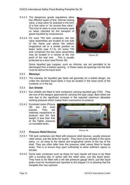
5.5.4.2 Sunshield tanks (Picture<br />
39) are the most<br />
popular. They are<br />
relatively inexpensive to<br />
produce and the tare<br />
weight is less than that<br />
<strong>of</strong> the higher pressure<br />
un-insulated tanks.<br />
5.5.5 Pressure Relief Devices<br />
Picture 39<br />
Picture 38<br />
5.5.5.1 T50 tank containers are fitted with pressure relief devices, usually pressure<br />
relief valves, just like tanks for liquids. They have to be situated in the same<br />
place, i.e. as close to the lateral and longitudinal centre <strong>of</strong> the top <strong>of</strong> the<br />
shell. They are <strong>of</strong>ten taller than the pressure relief valves fitted to liquids<br />
tanks. This is to ensure they open sufficiently to allow sufficient vapour to<br />
escape.<br />
5.5.5.2 Some tank containers such as those for toxic liquids will have to be fitted<br />
with a bursting disc in series with the relief valve, just like liquid tanks.<br />
They have to be fitted with a tell tale pressure gauge which, just like liquid<br />
tanks must be monitored and reported to the shipper if it is showing that the<br />
frangible disc has ruptured.<br />
Page 18 ©ICHCA International Limited