CR-150 CURRENT SENSING LOAD CONTROL ... - Load Controls Inc
CR-150 CURRENT SENSING LOAD CONTROL ... - Load Controls Inc
CR-150 CURRENT SENSING LOAD CONTROL ... - Load Controls Inc

Create successful ePaper yourself
Turn your PDF publications into a flip-book with our unique Google optimized e-Paper software.
<strong>CR</strong>-<strong>150</strong> <strong>CURRENT</strong> <strong>SENSING</strong> <strong>LOAD</strong> <strong>CONTROL</strong><br />
INSTALLATION, SET UP AND ADJUSTMENT<br />
+ -<br />
4-20<br />
MA OUTPUT<br />
REMOTE RESET<br />
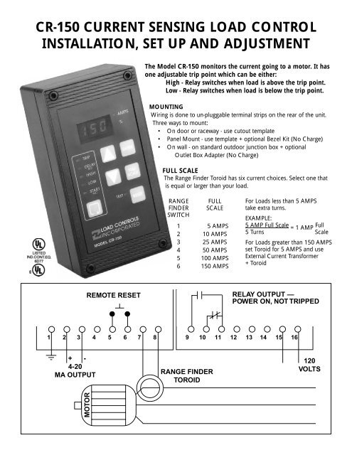
The Model <strong>CR</strong>-<strong>150</strong> monitors the current going to a motor. It has<br />
one adjustable trip point which can be either:<br />
High - Relay switches when load is above the trip point.<br />
Low - Relay switches when load is below the trip point.<br />
MOUNTING<br />
Wiring is done to un-pluggable terminal strips on the rear of the unit.<br />
Three ways to mount:<br />
• On door or raceway - use cutout template<br />
• Panel Mount - use template + optional Bezel Kit (No Charge)<br />
• On wall - on standard outdoor junction box + optional<br />
Outlet Box Adapter (No Charge)<br />
FULL SCALE<br />
The Range Finder Toroid has six current choices. Select one that<br />
is equal or larger than your load.<br />
RANGE FULL<br />
FINDER SCALE<br />
SWITCH<br />
1 5 AMPS<br />
2 10 AMPS<br />
3 25 AMPS<br />
4 50 AMPS<br />
5 100 AMPS<br />
6 <strong>150</strong> AMPS<br />
For <strong>Load</strong>s less than 5 AMPS<br />
take extra turns.<br />
EXAMPLE:<br />
5 AMP Full Scale<br />
= 1 AMP<br />
Full<br />
5 Turns Scale<br />
For <strong>Load</strong>s greater than <strong>150</strong> AMPS<br />
set Toroid for 5 AMPS and use<br />
External Current Transformer<br />
+ Toroid<br />
RELAY OUTPUT —<br />
POWER ON, NOT TRIPPED<br />
1 2 3 4 5 6 7 8 9 10 11 12 13 14 15 16<br />
MOTOR<br />
RANGE FINDER<br />
TOROID<br />
120<br />
VOLTS
RANGE FINDER TOROID<br />
3 1/2”<br />
2”<br />
2 3/8”<br />
FOR MOTORS LESS THAN 5 AMPS<br />
Take more “turns” of the leg through the Toroid. Each<br />
time the wire passes through the Toroid is a “turn”.<br />
This is one turn. This is two turns.<br />
FOR MOTORS GREATER THAN <strong>150</strong> AMPS<br />
A Current Transformer is used to reduce the primary<br />
current. The 5-amp secondary passes through the Toroid.<br />
Turn Dip Switch 1 on.<br />
Pass secondary of CT through toroid.<br />
1 1/8” Hole<br />
CAUTION<br />
When current is flowing through the primary of the<br />
external current transformer, always have a wire between<br />
the two brass Terminals on the CT.<br />
If they are left open, dangerous and destructive voltages<br />
can develop.<br />
HOOKING UP THE RESET<br />
Control can be reset three ways:<br />
• Manually with the Reset button on the control.<br />
• Remotely with a remotely located reset button<br />
or relay.<br />
• Automatic with a jumper.<br />
Remote Reset-<br />
Momentarily connect Terminal 5 to Terminal 6.<br />
Automatic Reset-<br />
Jumper Terminal 5 to Terminal 6.<br />
The terminals for Reset generate a small amount of<br />
current (8-12 milliamps). To reset, you just need to<br />
connect the terminal to the circuit common (Terminal 6).<br />
The switches or relays that you use must be suitable for<br />
low current (Gold flashed contacts, Reed Relays, Mercury<br />
Switches).<br />
4-20 MILLIAMP ANALOG OUTPUT<br />
The Analog Output is directly proportional to Full Scale<br />
capacity. It is always active. 500 ohm maximum connected<br />
impedance.<br />
Terminal 2 4-20mA Positive<br />
Terminal 3 4-20mA Negative<br />
Use twisted pair or in noisy environments, use shielded<br />
cable. Ground shield at other end.<br />
The Full Scale capacity to scale external meter, chart<br />
recorders or computers is the Dip Switch setting of the<br />
Toroid (or CT if one is used).<br />
THE <strong>CR</strong>-<strong>150</strong> POWERS THE 4-20MA SIGNAL.<br />
DON’T USE AN EXTERNAL DC POWER SUPPLY.<br />
SPECIFICATIONS <strong>CR</strong>-<strong>150</strong><br />
ENCLOSURE<br />
Glass-filled Polycarbonate<br />
NEMA 4, 4X - STYLE<br />
(3 1/4” x 6 1/4” x 2”)<br />
(83 mm x 160 mm x 54 mm)<br />
CAPACITY<br />
<strong>150</strong> AMPS directly<br />
through Toroid<br />
Large motors with external<br />
Current Transformer & Toroid<br />
DIGITAL <strong>LOAD</strong> DISPLAY<br />
.4” LED 3 Digit<br />
RELAY OUTPUT<br />
Form C 3 AMP @ 300 VAC or<br />
1/8 HP @ 240 VAC<br />
Latch when tripped<br />
ANALOG OUTPUT<br />
4-20mA; powered by the<br />
<strong>CR</strong>-<strong>150</strong> 500 OHM<br />
maximum connected<br />
impedance<br />
RESPONSE TIME<br />
50 Milliseconds<br />
TEMPERATURE<br />
0ºC - 55ºC<br />
TIMERS<br />
Start-up and Trip Delay<br />
0-90 second<br />
0-2 second in .1 second<br />
increments<br />
2-90 second in 1 second<br />
increments
TO SET FULL SCALE<br />
• Take Dip Switches of the Toroid (or CT if one is used),<br />
determine your Full Scale.<br />
• Decide if you want to display AMPS or %.<br />
FULL<br />
• The SCALE cycles through the choices shown below and<br />
blinks slowly for each choice. Each press of FULL moves<br />
SCALE<br />
you to the next choice.<br />
TO DISPLAY % OF YOUR MOTOR FULL <strong>LOAD</strong><br />
To display % of your motor load requires 1 calculation.<br />
“RATIO” =<br />
Enter this “Ratio” as Full Scale.<br />
Full Scale Capacity x 100<br />
Your Motor Size<br />
The Ratio must be greater than 100. If it isn’t, change<br />
your hook-up to a higher capacity.<br />
The display will now read 100% when your motor<br />
reaches its Full <strong>Load</strong>.<br />
FRONT PANEL SET-UP TIPS<br />
1) None of the settings will be changed until you hold<br />
down and the fast blinking stops.<br />
ENTER<br />
2) Five seconds after you have pressed a button, the<br />
Control will return to normal operation.<br />
3) If you hold down the digits will continue to<br />
change.<br />
FULL<br />
4) You only need to do SCALE when you install the Control<br />
(or if you change the hook-up).<br />
DIGITS ® DECIMAL ® DECIMAL ® DECIMAL ® AMPS ® %<br />
XXX. XX.X X.XX<br />
to change if this is if this is if this is if this is if this is<br />
your choice, your choice, your choice, your choice, your choice,<br />
press press press press press<br />
¯ ¯ ¯ ¯ ¯ ¯<br />
ENTER ENTER ENTER ENTER ENTER ENTER<br />
until fast until fast until fast until fast until fast until fast<br />
blink stops blink stops blink stops blink stops blink stops blink stops<br />
TO VIEW AND CHANGE THE SET POINTS<br />
AND DELAY TIMES<br />
cycles through the choices. The LED for each choice<br />
will turn ON.<br />
To change a setting, use<br />
Press ENTER until quick blinking stops to store your new<br />
choice.<br />
After 5 seconds if you haven’t pressed any buttons,<br />
control will return to normal operation.<br />
For High Trip - Relay will switch when load is ABOVE the<br />
Set Point.<br />
Press until display shows HHH<br />
Hold ENTER until high LED stops blinking<br />
For Low Trip - Relay will switch when load is BELOW the<br />
Set Point.<br />
Press until display shows LLL<br />
Hold ENTER until low LED stops blinking<br />
The High or Low LED will remain on during normal<br />
operation.<br />
Start-up Timer<br />
The Start-up Timer bypases the Control during motor<br />
start-up to avoid false trips because of current inrush. For<br />
convenience, the TIMING BEGINS WHEN THE MOTOR<br />
STARTS. The Start-up LED stays lit until the start-up period<br />
is over.<br />
The start-up time should be:<br />
• Long enough so that the load has stabilized.<br />
To bypass Start-up Timer set time to zero seconds.<br />
Delay Timers<br />
To avoid nuisance trips from short overloads, Delay<br />
Timers bypass the Control for the selected time. The<br />
relays won’t trip until the time is exceeded. If the trip<br />
condition goes away before the time is up, the timer<br />
resets to zero.<br />
• Start with minimum Delay. If you are getting trips<br />
where you don’t want them, increase the Delay<br />
Time.
11/2001<br />
53 10 TECHN PICKER OROAD LO GY PARK RO AD<br />
888-600-3247<br />
888-600-3247<br />
508-347-2606<br />
STURBRIDGE, STURBRIDGE, MA M A 01566 FAX 508-347-2064