Download Installation Manual For PFR-1550 in ... - Load Controls Inc
Download Installation Manual For PFR-1550 in ... - Load Controls Inc
Download Installation Manual For PFR-1550 in ... - Load Controls Inc
- No tags were found...
You also want an ePaper? Increase the reach of your titles
YUMPU automatically turns print PDFs into web optimized ePapers that Google loves.
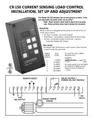
<strong>PFR</strong>-<strong>1550</strong> LOAD AD CONTROLOLINSTALLALLATION, SET UP AND ADJUSTMENTThe Model <strong>PFR</strong>-<strong>1550</strong> monitors ors the true power go<strong>in</strong>g to a motoror.By sens<strong>in</strong>g power (volts x amps x power factor) rather than justamps, there is much greater er sensitivity. . It has one adjustableabletrip po<strong>in</strong>t which can be either:High - Relaelay swithces when load is above the trip po<strong>in</strong>tLow - Relaelay switches when load is below the trip po<strong>in</strong>t.MOUNTINGWir<strong>in</strong>g is done to un-pluggable term<strong>in</strong>al strips on the rear of the unit.Three ways to mount:• On door or raceway - use cutout template• Panel Mount - use template + optional Bezel Kit (No Charge)• On wall - on standard outdoor junction box + optionalOutlet Box Adapter (No Charge)VOLTAGE120 volts AC is taken from two of the phases. If the motor starteralready has a 120-volt control transformer with 10VAof free capacity, it can be used. Otherwise, <strong>in</strong>stall a separatetransformer. It is okay if the secondary is grounded.BE SURE TO NOTE WHICH TWO PHASES SUPPLY THETRANSFORMER.In 120/208V three-phase system, the 120V MUST come from atransformer connected to two of the phases. The 120V phase to groundvoltage cannot be used.CURRENTThe current signal is taken from the REMAINING phase.This current sample passes through the Range F<strong>in</strong>der Toroid.It is VERY IMPORTANT that the current signal comes from the phase thatIS NOT supply<strong>in</strong>g the 120V control transformer. Be extra careful whenthe mach<strong>in</strong>e has revers<strong>in</strong>g starters or multi-speed w<strong>in</strong>d<strong>in</strong>gs. If a wrongphase is used the control will either:• Work backwards • Have reduced sensitivityIf you are us<strong>in</strong>g a variable frequency drive, use a different control.Call LOAD CONTROLS, INC. for help.LOAD CONTROLSINCORPORATED
REMOTE RESETRELAY OUTPUT —POWER ON, NOT TRIPPED1 2 3 4 5 6 7 8 9 10 11 12 13 14 15 16+ -4-20MA OUTPUTMOTORRANGE FINDERTOROIDCURRENT FROMREMAINING PHASEVOLTAGE TRANSFORMERWITH 120V SECONDARYMOTOR STARTERFULL SCALE CAPACITCITY AT 460 VOLOLTSThe Range F<strong>in</strong>der Toroid has six motor size choices.Select one that is equal or larger than your motor. Thiswill leave some headroom.• <strong>For</strong> motors less than 5 HP (460 volt), take extra turns.• <strong>For</strong> motors greater than 50 HP, use Range F<strong>in</strong>derToroid + Current Transformer.MOTOR FULL % FULL RANGE TURNS CURRENTSIZE SCALE LOAD FINDER TRANS-CAPACITY SWITCH FORMER1/2 HP .6 HP 123 2 ON 81 1.25 123 2 ON 41-1/2 1.65 109 2 ON 32 2.70 134 2 ON 23 3.80 128 3 ON 25 5.50 110 2 ON 17-1/2 8.25 110 3 ON 110 11.0 110 4 ON 115 27.5 183 5 ON 120 27.5 137 5 ON 125 27.5 110 5 ON 130 55.0 183 6 ON 140 55.0 138 6 ON 150 55.0 110 6 ON 160 84.0 140 1 ON 1 100:575 84.0 112 1 ON 1 100:5100 130 130 1 ON 1 150:5125 130 104 1 ON 1 150:5150 173 115 1 ON 1 200:5200 216 108 1 ON 1 250:5250 260 104 1 ON 1 300:5300 346 115 1 ON 1 400:5MULTIPLIERS<strong>For</strong> nom<strong>in</strong>al voltages other than 460 volts,multiply 460V full scale by:208V = .45230V = .5380V = .83415V = .9575V = 1.25<strong>For</strong> Kilowatts multiply Full Scale HP x .746<strong>For</strong> motor sizes or capacities not <strong>in</strong> table:% Full <strong>Load</strong> = Full Scale Capacity x 100Your Motor Size
RANGE FINDER TOROROIDOIDHOOKING UP THE RESETControl can be reset three ways:• <strong>Manual</strong>ly with the Reset button on the control.• Remotely with a remotely located reset buttonor relay.• Automatic with a jumper.3 1/2”1 1/8” HoleRemote Reset-Momentarily connect Term<strong>in</strong>al 5 to Term<strong>in</strong>al 6.Automatic Reset-Jumper Term<strong>in</strong>al 5 to Term<strong>in</strong>al 6.2”2 3/8”The term<strong>in</strong>als for Reset generate a small amount ofcurrent (8-12 milliamps). To reset, you just need toconnect the term<strong>in</strong>al to the circuit common (Term<strong>in</strong>al 6).FOR MOTORS ORS LESS THAN 5 HPTake more “turns” of the leg through the Toroid. Eachtime the wire passes through the Toroid is a “turn”.The switches or relays that you use must be suitable forlow current (Gold flashed contacts, Reed Relays, MercurySwitches).4-20 MILLIAMP ANALOG OUTPUTThe Analog Output is directly proportional to Full Scalecapacity. It is always active. 500 ohm maximum connectedimpedance.Term<strong>in</strong>al 2 4-20mA PositiveTerm<strong>in</strong>al 3 4-20mA NegativeThis is one turn.This is two turns.FOR MOTORS ORS GREATER THAN 50 HPA Current Transformer is used to reduce the primarycurrent. The 5-amp secondary passes through the Toroid.Use twisted pair or <strong>in</strong> noisy environments, use shieldedcable. Ground shield at other end.Use the Full Scale capacity from the chart to scaleexternal meter, chart recorders or computers.THE <strong>PFR</strong>-<strong>1550</strong> POWERS THE 4-20MA SIGNAL.DON’T USE AN EXTERNAL DC POWER SUPPLY.SPECIFICATIONS <strong>PFR</strong>-<strong>1550</strong>Pass secondary of CT through toroid.CAUTIONWhen current is flolow<strong>in</strong>g through the primary of theexternal ernal current transformerormer, , always s have a wire betweenthe two brass Term<strong>in</strong>als on the CT.If they are left t open, dangerous and destructivtive voltoltagagescan develop.elop.ENCLOSUREGlass-filled PolycarbonateNEMA 4, 4X - STYLE(3 1/4” x 6 1/4” x 2”)(83 mm x 160 mm x 54 mm)CAPACITCITYTo 50 horsepower directlythrough ToroidTo 500 horsepower with externalCurrent Transformer & ToroidDIGITAL LOAD DISPLAY.4” LED 3 DigitRELAY OUTPUT<strong>For</strong>m C 3 AMP @ 300 VAC or1/8 HP @ 240 VACLatch when trippedANALOG OUTPUT4-20mA; powered by the<strong>PFR</strong>-<strong>1550</strong> 500 OHMmaximum connectedimpedanceRESPONSE TIME25 MillisecondsTEMPERATURETURE0ºC - 55ºCTIMERSStart-up and Trip Delay0-90 second0-2 second <strong>in</strong> .1 second<strong>in</strong>crements2-90 second <strong>in</strong> 1 second<strong>in</strong>crements
TO SET FULL SCALE• After hook-up, f<strong>in</strong>d your HP, KW or % from the chart.• Decide if you want to display HP, % or KW.FULL• The SCALE cycles through the choices shown below andbl<strong>in</strong>ks slowly for each choice. Each press ofFULLmovesSCALEyou to the next choice.FRONT PANEL SET-UP TIPS1) None of the sett<strong>in</strong>gs will be changed until you holddown and the fast bl<strong>in</strong>k<strong>in</strong>g stops.ENTER2) Five seconds after you have pressed a button, theControl will return to normal operation.3) If you hold down the digits will cont<strong>in</strong>ue tochange.FULL4) You only need to do SCALE when you <strong>in</strong>stall the Control(or if you change the hook-up).DIGITS → DECIMAL → DECIMAL → DECIMAL → HP → % → KWXXX. XX.X X.XXto change if this is if this is if this is if this is if this is if this isyour choice, your choice, your choice, your choice, your choice, your choice,press press press press press press↓ ↓ ↓ ↓ ↓ ↓ ↓ENTER ENTER ENTER ENTER ENTER ENTER ENTERuntil fast until fast until fast until fast until fast until fast until fastbl<strong>in</strong>k stops bl<strong>in</strong>k stops bl<strong>in</strong>k stops bl<strong>in</strong>k stops bl<strong>in</strong>k stops bl<strong>in</strong>k stops bl<strong>in</strong>k stopsTO VIEW AND CHANGE THE SET POINTSAND DELAY TIMEScycles through the choices. The LED for each choicewill turn ON.To change a sett<strong>in</strong>g, usePress ENTER until quick bl<strong>in</strong>k<strong>in</strong>g stops to store your newchoice.After 5 seconds if you haven’t pressed any buttons,control will return to normal operation.<strong>For</strong> High Trip - Relay will switch when load is ABOVE theSet Po<strong>in</strong>t.Press until display shows HHHHold ENTER until high LED stops bl<strong>in</strong>k<strong>in</strong>g<strong>For</strong> Low Trip - Relay will switch when load is BELOW theSet Po<strong>in</strong>t.Press until display shows LLLStarart-up TimerThe Start-up Timer bypases the Control dur<strong>in</strong>g motorstart-up to avoid false trips because of current <strong>in</strong>rush. <strong>For</strong>convenience, the TIMING BEGINS WHEN THE MOTORSTARTS. The Start-up LED stays lit until the start-up periodis over.The start-up time should be:• Long enough so that the load has stabilized.To bypass Start-up Timer set time to zero seconds.Delay TimersTo avoid nuisance trips from short overloads, DelayTimers bypass the Control for the selected time. Therelays won’t trip until the time is exceeded. If the tripcondition goes away before the time is up, the timerresets to zero.• Start with m<strong>in</strong>imum Delay. If you are gett<strong>in</strong>g tripswhere you don’t want them, <strong>in</strong>crease the DelayTime.Hold ENTER until low LED stops bl<strong>in</strong>k<strong>in</strong>gThe High or Low LED will rema<strong>in</strong> on dur<strong>in</strong>g normaloperation.3/2013LOAD CONTROLSINCORPORATED888-600-324753 Technology Park Road 508-347-2606Sturbridge, MA 01566 FAX 508-347-2064


